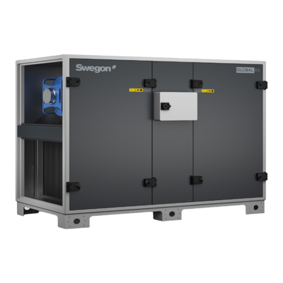
Swegon GLOBAL PX Operation And Maintenance Instructions

Swegon GLOBAL PX Operation And Maintenance Instructions

Applicable to program versions tac5 – version dt 2.8.8 & dg 2.7.3
Hide thumbs Also See for GLOBAL PX:

Advertisement

GLOBAL PX/RX/LP
Operation and maintenance instructions
Applicable to program versions TAC5 – Version DT 2.8.8 & DG 2.7.3
GLOBAL PX
GLOBAL RX
GLOBAL LP
GLOBAL PX
(FW)
FW
GLOBAL RX TOP
GLOBAL PX TOP
FW

Advertisement

Table of Contents
loading

Summary of Contents for Swegon GLOBAL PX

  • Page 1 GLOBAL PX/RX/LP Operation and maintenance instructions Applicable to program versions TAC5 – Version DT 2.8.8 & DG 2.7.3 GLOBAL PX GLOBAL RX GLOBAL LP GLOBAL PX (FW) GLOBAL RX TOP GLOBAL PX TOP...
  • Page 2: Table Of Contents

    GLOBAL PX/RX/LP Table of content Safety precautions Symbols and abbreviations Product Overview Wiring Overview Functions Commissioning Commissioning with Touchscreen interface Preventive maintenance Troubleshooting Parameters/Commissioning Sheet 10.0 CE Declaration This document is an overview of technical specifications. Please do refer to our selection software for detailed and up-to-date information.
  • Page 3 3000/4000/6000 or water GLOBAL PX 800/1200/2000/ Yes, electrical Yes, electrical Left / Right Backward Counterflow 3000/4000/6000 or water GLOBAL PX TOP Yes, electrical 800/1200/2000 Yes, electrical Right Forward (FW) Counterflow or water GLOBAL RX 05/08/10/12/13/ Yes, electrical Left / Right...
  • Page 4: Safety Precautions

    Disclaimer Danger/Warning/Caution • RANGE OF APPLICATION All staff concerned shall acquaint themselves with these instructions before beginning any work on the The GLOBAL units are designed for use in comfort unit. Any damages to the unit or its components ventilation applications. caused by improper handling or misuse by the Depending on the variant selected, GLOBAL units can be purchaser or the installer cannot be considered...
  • Page 5: Symbols And Abbreviations

    2.0 Symbols and abbreviations BACKWARD FORWARD CURVED FAN CURVED FAN BAG FILTER PLEATED FILTER ROTARY HEAT PLATE HEAT EXCHANGER EXCHANGER WARNING Must be connected by a qualified Electrician. Warning! Hazardous voltage. OUTDOOR AIR Air from outdoor to the AHU SUPPLY AIR Air from the AHU to the building EXTRACT AIR Air from the building to the AHU...
  • Page 6: Product Overview

    GLOBAL RX GLOBAL RX GLOBAL RX TOP GLOBAL RX TOP GLOBAL PX (FW) GLOBAL PX (FW) ATTENTION Right and left hand units have different article numbers and should be ordered accordingly. It is however possible to change the direction afterwards but only by an accredited Service technician.
  • Page 7 RIGHT HAND UNIT (SUPPLY AIR TO THE RIGHT) LEFT HAND UNIT (SUPPLY AIR TO THE LEFT) GLOBAL PX TOP FW GLOBAL PX TOP FW GLOBAL LP 450 (BOTTOM view) GLOBAL LP 450 (BOTTOM view) GLOBAL LP 600/1000/2000 FW (BOTTOM view)
  • Page 8 GLOBAL PX (FW) GLOBAL LP GLOBAL LP GLOBAL PX TOP 10. Modulating 100% by-pass (PX only) 1. Main power switch for AHU 11. Drain pan and drain pipe (PX only) 2. Main power switch for electrical coils (both internal pre-hating and post-heating) 12.
  • Page 9 3.3 AIR VOLUMES AND DIMENSIONS GLOBAL PX (FW) GLOBAL LP (FW) EXCHANGER SIZE AIR VOLUME A [mm] B [mm] C [mm] Weight [kg] 800 m³/h 222 l/s 1210 1235 (FW) 1200 1200 m³/h 333 l/s 1210 1235 (FW) 2000 1230 2000 m³/h...
  • Page 10 GLOBAL RX GLOBAL RX TOP 10. Modulating 100% by-pass (PX only) 1. Main power switch for AHU 11. Drain pan and drain pipe (PX only) 2. Main power switch for electrical coils (both internal pre-hating and post-heating) 12. Pre-heating electrical antifrost coil (PX only) 3.
  • Page 11 3.3 AIR VOLUMES AND DIMENSIONS GLOBAL RX (TOP) EXCHANGER SIZE AIR VOLUME A [mm] B [mm] C [mm] Weight [kg] 1100 m³/h 305l/s 1530 1315 1500 m³/h 416l/s 1530 1315 1600 m³/h 440l/s 1680 1465 GLOBAL RX TOP 2000 m³/h 555l/s 1680 1465...
  • Page 12: Wiring Overview

    4.0 Wiring Overview MAIN CONTROL BOARD TAC5 DG - CID025000 TAC5 DG: GLOBAL PX & LP CT = output to CT actuator(s) (option - prewired) IN1 = Master selection BYPASS = output to bypass actuator (prewired) IN2 = dPa (pressostat digital input)
  • Page 13 MAIN CONTROL BOARD TAC5 DT - CID026001 TAC5 DT: GLOBAL RX (TOP) & LP (FW) CT : output to CT actuator(s) (option - prewired) IN1 = Master selection KWout = output for KWout capacity control (option - prewired) IN2 = dPa (pressostat digital input) AL1 = ALARM OUTPUT (230V/5A) IN3 = Fire alarm input B- / A+ / GND / +12V = connection to HMI...
  • Page 14 4.1 CIRCUIT BOARD SAT 3 - CID3 72 005 Fig. 1 The SAT3 circuit board is used for extra functions for which inputs and outputs are not included as standard in the control unit of the air handling unit. All outputs are normally open (N.O.).
  • Page 15 4.3 INTERNAL WIRING DIAGRAM GLOBAL PX Operation and maintenance instructions – v2.8.8 & 2.7.3...
  • Page 16 4.4 INTERNAL WIRING DIAGRAM GLOBAL RX (TOP) Operation and maintenance instructions – v2.8.8 & 2.7.3...
  • Page 17 4.5 INTERNAL WIRING DIAGRAM GLOBAL LP Operation and maintenance instructions – v2.8.8 & 2.7.3...
  • Page 18: Functions

    5.0 Functions 5.1 OPERATING MODE There are five main operating modes. The operating In all the operating modes, the supply fan(s) will operate mode determines how the airflow or the fan torque as per the assigned mode and parameters. The exhaust is modulated.
  • Page 19 5.2 TEMPERATURE CONTROL There are several options available on GLOBAL units to ensure a comfortable temperature. The options are controlled either via supply or extract air temperature. Supply Air Temperature Supply temperature control is the default setting. This involves keeping a constant supply air temperature without consideration to the load in the premises.
  • Page 20 5.4 COOLING RECOVERY (RX ONLY) The cooling recovery function uses the lower extract air temperature to cool down the fresh air. The function is not configurable. If there is a cooling load in the building and the temperature in the extract air is lower than the outdoor air temperature, the heat exchanger shall be automatically controlled to operate at maximal speed.
  • Page 21 5.6 FROST PROTECTION HEATING COIL The frost protection function is always active if the activated when the surface temperature of the coil drops heating coil has been correctly configured in the product below 5°C. Under these conditions the pump output is setup.
  • Page 22 5.7 TIME SCHEDULE The controller allows 4 time slots (channels) to be configured. For each day of the week, the operation mode can be either AUTO (operate according to time slots) or OFF. For each time slot select : • In airflow control mode: the airflow by selecting m³h K1 / m³h K2 / m³h K3 / OFF (stop) •...
  • Page 23: Commissioning

    6.0 Commissioning As a human machine interface (HMI), several options are available. The HMI will enable access to the control parameters in the integrated controller. The HMI as such does not contain any programming and therefor is not mandatory. The possible HMIs are: TACtouch touchscreen - CID3 72 096 This 4.3”...
  • Page 24 6.1 COMMISSIONING WITH TACtouch INTERFACE The hand-held terminal consists of a 4.3” touch screen with a 1,5 metre long cable for connection to the air handling unit's control circuit board. If the hand-held terminal is not used for 20 minutes, it switches over to the sleep mode. The Touchscreen controller can be used outdoors, but it must be kept at a weatherproof place.
  • Page 25 Current operation status 6.1.1 HOME SCREEN The home screen displays the current key data for the air han- dling unit and is shown is normally displayed if no other menu has been selected or if selected from the main menu. The touch screen switches to the sleep mode after 20 minutes.
  • Page 26 6.1.2 Main menu The main menu consists of a rotary menu with 7 icons. Control The control menu will allow for the user to change basic parameters and operation status of the unit. The unit can be switched on/off The fan speed can be selected; three manual speeds + one auto speed Post heating, post cooling and free cooling setpoints can be changed.
  • Page 27 BASIC SETUP Basic Setup LANGUAGE The basic setup menu will guide the user through the UNITS most critical settings of the air handling unit. This setup procedure is described in detail, section 6.1.3 AIRFLOW REGULATION TEMPERATURE FIRE ALARM Readings The operating status and the Settings can be read. Used for performance checks and for generally checking Set- tings, settings, power consumption, etc.
  • Page 28 6.1.3 BASIC SETUP When the air handling unit is started up for the first time, the commissioning menu is automatically displayed. At the very end of the commissioning (menu) the commissioning of the unit has to be confirmed by the service technician. Once the commis- sioning has been confirmed, the commissioning menu will not BASIC SETUP be displayed as first menu any more.
  • Page 29 Constant airflow Demand control Flow control involves operating the air handling unit to The airflow desired is regulated in response to 0-10 V keep the preset airflow constant. The speed of the fans is input signals from an external sensor, such as a carbon automatically regulated to provide correct airflow even if dioxide or a humidity sensor.
  • Page 30 Temperature BASIC SETUP LANGUAGE The temperature control can be configured as a supply air control or an extract air control. By default, this function is configured as a supply air temperature UNITS control. Changes to this configuration are done in the advanced setup; see AIRFLOW REGULATION Section 6.1.4 TEMPERATURE...
  • Page 31 6.1.4 ADVANCED SETUP N.B.! The appearance and content of this menu varies depending on the type of air handling unit and functions and/or options selected. A code and a special training are needed to access this menu. Attention: The settings range for most of the functions ADVANCED SETUP is defined for maximal flexibility.
  • Page 32 Stop fan when pressure alarm ADVANCED SETUP 2ND 0...10 CONTROL SIGNAL Possibility to stop the fans automatically in case of a pressure alarm. CONSTANT PRESSURE STOP FAN Setting Settings Factory START TORQUE range setting DEACTIVATE SOFTSTOP Stop fans Start torque ADVANCED SETUP Possibility to change the fans’s starting torque.
  • Page 33 Boost ADVANCED SETUP The boost mode can be used to force the supply and extract DEACTIVATE SOFTSTOP airflow to a higher setpoint, when specific conditions are met. TEMPERATURE The boost mode can be activated with a contact connected to BOOST the digital input IN9 or by an analogue 0...10V control signal POST VENTILATION connected to input K3.
  • Page 34 Internal coils ADVANCED SETUP Water preheating coil BOOST By preheating the outdoor air, it is possible to prevent mois- POST VENTILATION ture precipitation in the AHU’s outdoor air filter, to reduce INTERNAL COILS the risk of frosting in the heat exchanger and to eliminate EXTERNAL COILS the risk that pressure sensors and motor control systems are INTERNAL COILS...
  • Page 35 External coils ADVANCED SETUP Configuration of the coils BOOST This menu will allow for the configuration of any combi- POST VENTILATION nation of external heating and or cooling coil(s). EXTERNAL COILS FROST PROTECTION Setting Settings Factory FREECOOLING range setting Type None None Hot water...
  • Page 36 Frost protection Frost protection heating and cooling coils Frost protection plate heat exchangers (PX) The water coils are always protected against freezing by In environments where the extract air can occasionally an anti-frost temperature sensor. This sensor is monted be humid, the defrosting function can be activated to on the surface of the water coil.
  • Page 37 0-10V output Modbus configuration The controller has as a standard feature two configur- The MODBUS RTU communication requires an additional able analogue 0...10V outputs. The outputs represent the satellite circuit (CID050043) which is used as commu- actual airflow (or torque) or the actual pressure delivered nication interface.
  • Page 38: Preventive Maintenance

    7.0 Preventive maintenance Attention : before handling and/or opening the access panels it is compulsory to shut down the unit and disconnect the power supply using the general switch located on the front panel. Do not isolate the power supply whilst the unit is running. If KWin and\or KWout are installed, then isolate the corresponding power supplies.
  • Page 39 7.3 EVERY 12 MONTHS 1. For rotary heat exchanger (RX) units, check the brush seals on the rotary heat exchanger along the perimeter in contact with the frame: If necessary, bring the brush seals closer to the exchanger to ensure good sealing. 2.
  • Page 40: Troubleshooting

    8.0 Troubleshooting The TAC5 control board generates and reports 18 types of alarms. The alarms are subdivided into auto resetting and non-auto resetting alarms. For the latter, a reset will be necessary once the problem has been resolved. For each type of alarm, a full text description will be displayed on the user interface depending on the alarm type: - Activation of contact relay (NC or NO contact)- AL 1 - Activation of SAT3 OR1 in case of pressure alarm, provided that the optional module SAT 3 is installed on the control board.
  • Page 41 8.2 TYPE 2: ALARM ON THE PRESSURE VARIATION - Conditions: • Mode airflow control or demand control. Unit must have forward fans or backward fans with kit CA. • External pressostat connected on IN2 input - Causes: • Pressure alarm setup in airflow control or demand control mode •...
  • Page 42 8.3 TYPE 3: ALARM REPORT DURING REFERENCE PRESSURE INITIALIZATION - Conditions: • Mode Airflow control or Demand control: during the initialization of the pressure alarm. In this case, the unit must have forward fans or backward fans with kit CA. •...
  • Page 43 8.4 TYPE 4: ALARM INDICATING THE SYSTEM CANNOT FULFIL THE SETPOINT - Conditions: - Causes: • The setpoint cannot be fulfilled because the upper or lower limit of the fan’s working zone has been reached - Effects: Displayed on HMI Text displayed LED ALARM LED Pa...
  • Page 44 8.6 TYPE 6: FIRE ALARM - Conditions: • Fire alarm input must be connected to a fire detection system - Causes: • Activation of fire alarm input, IN3, connected to a fire detection system. IN3 can be configured to work as NO open contact by default or as NC if configured so in the advanced setup. - Effects: Displayed on HMI Text displayed...
  • Page 45 8.7 TYPE 7: MAINTENANCE ALARM - Conditions: • the running hours feature must be enabled in advanced setup - Causes: • SERVICE ALARM: the fan operating time (in hours) has exceeded the configurable threshold • STOP FAN: the fan operating time (in hours) has exceeded the configurable threshold. This alarm stops the fans - Effects: Displayed on HMI Text displayed...
  • Page 46 8.9 TYPE 9: ALARM INDICATING A T° SENSOR T1/T2/T3 FAILURE - Conditions: - Causes: • One or more of the T° sensors T1/T2/T3 connected to the TAC5 circuit and mounted on heat exchanger is defect or not connected. These sensors are needed for the bypass control and the anti-frost procedure. - Effects: Displayed on HMI Text displayed...
  • Page 47 8.11 TYPE 10 BIS: DRAIN PUMP ALARM - Conditions: • Only for GLOBAL LP - Causes: • The level of condensate is higher than a set Setting (approx. 1.5 cm). It can also be activated if the pump is not present or defective - Effects: Displayed on HMI Text displayed...
  • Page 48 8.13 TYPE 12: ALARM INDICATING THAT THE COMFORT T° IS TOO LOW RELATIVE TO SETPOINT T° - Conditions: • Only with post-heating option - Causes: • The comfort T° setpoint cannot be reached (actual T° lower than setpoint during 15 minutes, or 30 minutes if comfort on T2 instead of T5, while post heating is at maximum.) - Effects: Displayed on HMI...
  • Page 49 8.14 TYPE 13: ALARM INDICATING HEAT EXCHANGER FROST PROTECTION ALERT - Conditions: • Only with post-heating option - Causes: • For PX units: Frost protection is only selected with electrical pre-heating coil (KWin) or water preheating coil (BAin) or modulating bypass.
  • Page 50 8.15 TYPE 14: ALARM INDICATING FROST PROTECTION ALERT – FANS STOPPED T° - Conditions: • Frost protection is only selected for PX units with electrical preheating (KWin) or water preheating (BAin) or if modulating bypass - Causes: • With KWin or BAin option: in certain air T° conditions as measured on the exhaust airflow after the heat recovery, indicating that the internal electrical KWin coil or external hydraulic coil (BAin) has reached its limit, the TAC5 control can take over to guarantee the anti-frost function.
  • Page 51 8.16 TYPE 14 BIS: ALARM INDICATING AN ERROR ON THE HEAT EXCHANGER ROTATION SPEED - Conditions: • Only for RX units - Causes: • This alarm indicates that the rotation speed of the wheel has been lower or greater than 15% of the setpoint speed for more than 5 minutes - Effects: Displayed on HMI...
  • Page 52 7.18 TYPE 16: ALARM INDICATING THAT THE SUPPLY T° IS TOO LOW - Conditions: • Only with post heating or cooling option - Causes: • This alarm indicates that the supply temperature (T5) is lower than 5°C. The fans are stopped for 1 minute. The alarm is configurable through the advanced setup and is disabled by default.
  • Page 53 8.20 TYPE 18: ALARM INDICATING AN INCORRECT POSITION OF THE MODULATING BYPASS RELATIVE TO THE ORDERED POSITION - Conditions: • PX units with modulating bypass - Causes: • This alarm indicates that the modulating bypass has not reached the ordered position within 10 seconds. The most common reason for this is a damaged position sensor on the bypass actuator, and this must be replaced.
  • Page 54 8.22 TYPE 20: ALARM INDICATING THAT THE DEFROST PROCESS IS ACTIVE - Conditions: • Unit with counter flow heat exchanger - Causes: • The ice forming inside of the plate heat exchanger is genrating a pressure drop that is to high for the current airflow. This detection requires a Modbus pressure sensor placed on the heat exchanger and that the modulation of the fans speed is based on the airflow and not on torque •...
  • Page 55 8.23 REC TABLE In the control board the “REC type” is used to define the type unit. When replacing the control board, the REC type needs to be configured in the product setup menu. The product setup menu is used to enable specific features or to modify factory settings. This must be done by an accredited technician.
  • Page 56: Parameters/Commissioning Sheet

    9.0 Parameters/Commissioning Sheet Please enter all settings specific to your installation in this table. Please keep this document at hand when there is a need to contact us to report a problem. 9.1 MAIN PARAMETERS AFTER COMMISSIONING GLOBAL model: Constant Airflow Constant Torque Operating mode: Demand control...
  • Page 57 9.2 TRACK CHANGES Enter details when the Setting of a parameter has been changed (use only one row per parameter): Setting before Setting of Date of Setting of Date of Parameter Name change change #1 change #1 change #2 change #2 Operation and maintenance instructions –...
  • Page 58 B5030 Gembloux Hereby declares that: Following product range(s): GLOBAL PX (TOP) / GLOBAL RX (TOP) / GLOBAL LP / CLASS UNIT / MURAL Complies with the requirements of Machinery Directive 2006/42/EC. Complies also with applicable requirements of the following EC directives:...
  • Page 60 We make every breath count. Version: 27/09/2018 We reserve the right for changes.

This manual is also suitable for:

Global rxGlobal px top fwGlobal rx topGlobal lp fwGlobal px fw

Table of Contents