
Subscribe to Our Youtube Channel
Related Manuals for HMS Anybus 024380-C


Summary of Contents for HMS Anybus 024380-C
- Page 1 M-Bus to Modbus-TCP Gateway 024380-C, 025070-C USER MANUAL SCM-1202-0096-EN 2.1 ENGLISH...
- Page 2 Important User Information Liability Every care has been taken in the preparation of this document. Please inform HMS Industrial Networks AB of any inaccuracies or omissions. The data and illustrations found in this document are not binding. We, HMS Industrial Networks AB, reserve the right to modify our products in line with our policy of continuous product development.
-
Page 3: Table Of Contents
Table of Contents Page Preface ..........................3 About This Document.....................3 Document History ......................3 Document Conventions ....................4 Product Description ....................... 5 Installation ........................6 Installation Overview ......................6 DIN Rail Mount ......................6 Connections and Indicators ....................7 Network Settings......................8 Configuration ........................9 Web Interface Login .......................9 General Tab.........................10 Meter Tab ........................ - Page 4 Table of Contents Advanced Configuration ..................... 37 FTP ..........................37 SSH..........................38 Ping ..........................38 Configuration Files .......................39 A Technical Data........................ 45 M-Bus to Modbus-TCP Gateway User Manual SCM-1202-0096-EN 2.1...
-
Page 5: Preface
Preface 3 (46) Preface About This Document This document describes how to install and configure the Anybus M-Bus to Modbus-TCP gateway, models 024380-C and 025070-C. For additional documentation, configuration examples, FAQs, troubleshooting guides and technical support, please visit www.anybus.com/support. Document History Version Date Description... -
Page 6: Document Conventions
This is a cross-reference within this document: Document Conventions, p. 4 This is an external link (URL): www.hms-networks.com This is additional information which may facilitate installation and/or operation. This instruction must be followed to avoid a risk of reduced functionality and/or damage to the equipment, or to avoid a network security risk. -
Page 7: Product Description
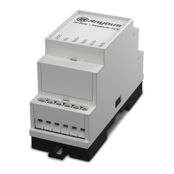
Product Description 5 (46) Product Description The Anybus M-Bus to Modbus-TCP gateway allows measuring devices that use the M-Bus protocol (meters) to communicate on a Modbus TCP network with up to 5 Modbus clients. Meters can be added manually or automatically by scanning the M-Bus. The gateway configuration maps data from each meter to a corresponding Modbus register. -
Page 8: Installation
Installation 6 (46) Installation This product contains parts that can be damaged by electrostatic discharge (ESD). Use ESD prevention measures to avoid damage. Installation Overview Mount the unit on a DIN rail. Connect the M-Bus and Ethernet cables. Connect the power supply and power on the unit. Check the network settings and configure them as required. -
Page 9: Connections And Indicators
Installation 7 (46) Connections and Indicators To ensure a good M-Bus signal, make sure that power ground (GND) is NOT electrically connected to protective earth (PE). Maximum cross sectional area in terminal block = 2.5 mm Terminal block Function 24VDC +24 VDC Power ground MBUS+... -
Page 10: Network Settings
Installation 8 (46) Network Settings The Anybus M-Bus to Modbus-TCP gateway is normally configured using the built-in web interface. The IP address of the gateway must be in the same subnet range of your local network as the computer used for configuration. Default network settings Static IP address 192.168.1.101... -
Page 11: Configuration
Configuration 9 (46) Configuration When power is applied the gateway will run the following startup sequence: Applying TCP/IP network settings using DHCP or static configuration Initial generation of SSL device keys (may take some time on first startup) Setting system time via SNTP Starting system services Starting the main application The Anybus M-Bus to Modbus-TCP gateway is normally configured using the web interface,... -
Page 12: General Tab
Configuration 10 (46) General Tab This tab contains general network settings. Fig. 5 General tab Field Description Writable Device name Name of the gateway (displayed in configuration tool) Serial number Serial number of the gateway DHCP Enable/disable dynamic IP addressing IP address IP address of the gateway Subnet mask... -
Page 13: Meter Tab
Configuration 11 (46) Meter Tab This tab lists the connected meters and allows you to add and edit individual entries. Fig. 6 Meter tab The meter list is initially empty. After connecting meters to the gateway, click Scan to start populating the list. - Page 14 Configuration 12 (46) The default configuration for each meter is applied immediately after scanning. Additional changes to the configuration must be saved manually. When activating or deactivating a meter, its meter values will automatically be enabled or disabled according to the hierarchy. An inactive meter will be activated when one of its meter values is enabled.
- Page 15 Configuration 13 (46) Editing Entries Fig. 7 Editing meter and value entries Meter and value entries can be configured by double-clicking the entry or by right-clicking the entry and selecting Edit. The fields in the Edit dialog correlate with the fields in the meter list. Depending on the used interface some fields may be disabled for editing.
-
Page 16: Configuration Tab
Configuration 14 (46) Configuration Tab This tab provides global meter settings. Fig. 8 Configuration tab Discard the changes made on the page and reload the currently active settings. Save the changes and reinitialize the gateway. Print Page, p. M-Bus to Modbus-TCP Gateway User Manual SCM-1202-0096-EN 2.1... - Page 17 Configuration 15 (46) Configuration tab fields Field Description Writable Readout interval (s) Standard readout cycle of meters (in seconds). Value might be overwritten for each meter by parameter Cycle in tab Meter Description mode Mode of displaying the meter value description. None No display of description Standard...
-
Page 18: Server Tab
Configuration 16 (46) Server Tab This tab provides settings for the Modbus TCP interface. Fig. 9 Server tab Server tab fields Field Description Writable Modbus mode Select Modbus TCP (default) or Modbus UDP. A maximum of 5 simultaneous connections from Modbus masters are accepted in Modbus TCP mode. -
Page 19: Security Tab
Configuration 17 (46) Security Tab This tab allows you to enable/disable access to the gateway over FTP, SSH and Telnet connections. Fig. 10 Security tab Server tab fields Field Description Writable FTP server active Enable FTP server SSH server active Enable SSH server Telnet server active Enable Telnet server... -
Page 20: User Tab
Configuration 18 (46) User Tab This tab allows you to create and manage users and assign them specific access rights. Fig. 11 User tab User tab fields Field Description Writable Name Username Overwrite password Not used Change password User is allowed to change his/her password Sessions Number of currently open session with this user account Maximum sessions... - Page 21 Configuration 19 (46) To edit the password and the maximum sessions setting, either double-click on the user entry or right-click on the entry and select Edit from the context menu. Fig. 12 Edit user Username cannot be changed once the user has been saved. FTP Access will only allow access to the log data directory (C:\log).
-
Page 22: Service Tab
Configuration 20 (46) Service Tab This tab provides read-only information about the hardware and software for support and troubleshooting. Fig. 13 Service tab Refresh the information on this page. (disabled) Restart the gateway and reinitialize all internal processes. Print Page, p. M-Bus to Modbus-TCP Gateway User Manual SCM-1202-0096-EN 2.1... -
Page 23: Print Page
Configuration 21 (46) Print Page Clicking Print on any tab in the web interface will export the complete configuration (not only the active tab) as a printable HTML page in a new browser tab or window. The Meter Configuration section will be output in a table format that can be copied and pasted directly into a spreadsheet program. -
Page 24: Modbus Tcp Specification
Identification Data Code Name Data type 20 UL model 80 UL model Type 0x00 VendorName String HMS Industrial Networks AB Basic 0x01 ProductCode String Basic 0x02 MajorMinorRevision String Basic 0x03 VendorUrl String www.anybus.com... - Page 25 Modbus TCP Specification 23 (46) Dummy Data For checking the data layout on the Modbus master side the gateway can be configured to generate dummy data. See Server Tab, p. The following data will be represented via the Modbus interface according to the register layout described in Meter Data Format, p.
-
Page 26: Acquiring And Processing Meter Data
Acquiring and Processing Meter Data 24 (46) Acquiring and Processing Meter Data The main task of the Anybus M-Bus to Modbus-TCP gateway is the processing and transmission of meter data. For proper operation, the following issues must be considered: The following requirements must be fulfilled for the Anybus M-Bus to Modbus-TCP gateway to process and transmit meter data: •... - Page 27 Acquiring and Processing Meter Data 25 (46) Adding Meters Manually Fig. 15 Adding a meter Meters that are connected but not found during a scan can be added manually by clicking on the Add button in the Meter tab. The configuration of the meter must be known to be able to add it manually.
-
Page 28: Meter Data Format
Acquiring and Processing Meter Data 26 (46) Meter Data Format The media IDs, value types and units used in meter data are defined in the EN 13757-3 standard. Custom types and units can be defined depending on the meter interface. Predefined Media ID values Index Description... - Page 29 Acquiring and Processing Meter Data 27 (46) Predefined Measurement Value Types Index Description Index Description None Access code developer Error flags (Device type specific) Password Digital output Error mask Special supplier information Baud rate Credit Response delay time Debit Retry Volts Remote control (device specific) Ampere...
- Page 30 Acquiring and Processing Meter Data 28 (46) Predefined Units Index Unit Description None None Binary Local currency units Volt Ampere Watt hour Joule Cubic meter Kilogram Second Minute Hour Watt Joule per Hour m^3/h Cubic meter per hour m^3/min Cubic meter per minute m^3/s Cubic meter per second kg/h...
- Page 31 Acquiring and Processing Meter Data 29 (46) Modbus Register Layout The Anybus M-Bus to Modbus-TCP gateway uses a fixed address structure of 10 Modbus registers per meter/meter value. Addresses are enumerated starting with 0. • Data types using more than one register are encoded with the most significant word at the lowest address.
- Page 32 Acquiring and Processing Meter Data 30 (46) Example Configuration In this example, the following data will be transmitted to the Modbus master: Address Value Name Decoded value Device entry 0x0002 Serial number 0x0002993A 0x993A 0x0001 Protocol version 0x006F Version Version = 0x006F = 111 = v1.11 0x519C 0x519CC16D = 1369227629 = Time stamp...
-
Page 33: Troubleshooting
Troubleshooting 31 (46) Troubleshooting This section lists some common problems and suggestions how to solve them. If none of the suggested actions solves the problem, please contact Anybus support. Hardware Errors Gateway is not responding After powering on the gateway it does not operate. Current consumption is ~0 mA and both Ethernet LEDs are unlit. -
Page 34: Network Errors
Troubleshooting 32 (46) Network Errors Web interface and FTP server inaccessible Run Net discover and check if the gateway appears in the list. • If the gateway is not listed, continue to No network connection. • If the gateway is listed: –... - Page 35 Troubleshooting 33 (46) Web session is unexpectedly terminated If the web session is unexpectedly terminated, this may be due to a connection timeout. The timeout limit can be increased by editing the system parameter WEBCOM_TIMEOUT. Configuration Files, p. A timeout may also occur if the gateway is currently busy with the collection and transmission of meter data, which takes priority over web communication.
-
Page 36: Meter Reading Errors
Troubleshooting 34 (46) Meter Reading Errors No meters are detected A scan has been completed but none of the connected meters appear in the meter list. Check the cable between the gateway and the meter and replace faulty cables. Check that the voltage between terminals MBUS+ and MBUS- is ~36 VDC. Check that the M-Bus interface (M-Bus mode) is enabled in the Configuration tab. - Page 37 Troubleshooting 35 (46) Meters are detected but have no data Some meters may contain a wrong declaration of the secondary address. These meters will be visible in the meter list but not addressable for meter readouts. The system parameter MBUS_SELECTMASK makes it possible to mask parts of the secondary address and replace them with a wildcard character.
-
Page 38: Meter Data Transmit Error
Troubleshooting 36 (46) Webserver capacity error message After a scan or a change in the meter list, the gateway (even after a reboot) may show the following error message in the meter list: The meter list exceeds the capacity of the internal webserver This error message is caused by an internal limitation of the webserver. -
Page 39: Advanced Configuration
Advanced Configuration 37 (46) Advanced Configuration The file system in Anybus M-Bus to Modbus-TCP gateway can be accessed directly for advanced configuration or troubleshooting. Right-clicking on the gateway in Net discover will open a context menu for accessing the file system in different ways. Fig. -
Page 40: Ssh
Advanced Configuration 38 (46) Secure shell access to the file system is possible using a terminal emulator such as PuTTY, which is bundled with Net discover and accessible from the context menu. After logging in as admin you can use shell commands to access the file system. Fig. -
Page 41: Configuration Files
Advanced Configuration 39 (46) Configuration Files The configuration files are updated when changes are made via the web interface. They can also be edited manually and downloaded to the gateway via FTP. Manual changes to the configuration files will take effect after the gateway has been rebooted. Some parameters can only be changed by editing the configuration files manually. - Page 42 Advanced Configuration 40 (46) M-Bus to Modbus-TCP Gateway User Manual SCM-1202-0096-EN 2.1...
- Page 43 Advanced Configuration 41 (46) M-Bus to Modbus-TCP Gateway User Manual SCM-1202-0096-EN 2.1...
- Page 44 Advanced Configuration 42 (46) M-Bus to Modbus-TCP Gateway User Manual SCM-1202-0096-EN 2.1...
- Page 45 Advanced Configuration 43 (46) Meter Configuration File Parent Element name Description Default value Example root version Version of XML specification 0x08 meter Parent element for each meter meter interface Interface to meter M-Bus serial Serial number of meter 0xFFFFFFFF 0x30101198 (hexadecimal notation with leading 0x) manufacturer Manufacturer of meter (abbreviation)
- Page 46 This page intentionally left blank...
-
Page 47: A Technical Data
Appendix A: Technical Data 45 (46) Technical Data Technical Specifications Model name Anybus M-Bus to Modbus-TCP gateway Order code 024380 025070 M-Bus max. number of unit loads M-Bus baud rates 300 to 19200 Bd M-Bus Uspace 36 V M-Bus Umark 24 V M-Bus max. - Page 48 © 2018 HMS Industrial Networks AB Box 4126 300 04 Halmstad, Sweden info@hms.se SCM-1202-0096-EN 2.1.7247 / 2018-02-01...
Need help?
Do you have a question about the Anybus 024380-C and is the answer not in the manual?
Questions and answers