
Subscribe to Our Youtube Channel
Related Manuals for Nonin 7600


Summary of Contents for Nonin 7600
- Page 1 Operator’s Manual Model 7600 4-Channel Regional Oximeter with Equanox™ Technology ® and Bluetooth Wireless Technology For Display Software Revision 11 and Higher English 0123...
- Page 2 Nonin is a registered trademark of Nonin Medical, Inc. The Bluetooth word mark and logos are owned by the Bluetooth SIG, Inc. and any use of such marks by Nonin Medical, Inc. is under license. Other trademarks and trade names are those of their respective owners.
-
Page 3: Table Of Contents
Federal Communications Commission (FCC) Notice....5 Guide to Symbols............... 6 Introduction to the Model 7600 ........10 Benefits of the Model 7600 Regional Oximetry System ..10 Setting Up the Model 7600 Monitor......... 11 Sensor Application ..............12 Bluetooth Technology ............. 13 Battery .................. - Page 4 Two-Channel Display............14 Figure 4. Four-Channel Display ..........14 Figure 5. Model 7600 Main Menu Screen Buttons....18 Figure 6. Model 7600 Limits Menu Screen Buttons ....19 Figure 7. Bluetooth Screen ............. 20 Figure 8. Model 7600 Limits Screen ........22 Figure 9.
- Page 5 Tables Table 1. Labeling Icons ............. 6 Table 2. Display Icons............... 7 Table 3. Button Icons ..............8 Table 4. Soft Button Icons............9 Table 5. Display Indicators and Icons ........16 Table 6. Front Panel Buttons ..........17 Table 7. Main Menu Buttons ........... 18 Table 8.
-
Page 6: Indications For Use
Use, which contains sensor application information for each sensor. Protect from exposure to water or any other liquid, with or without AC power. Use the Model 7600 only with power adapters supplied by Nonin Medical. As with all medical equipment, carefully route patient cables and connections to reduce the possibility of entanglement or strangulation. -
Page 7: Cautions
Indications for Use Warnings (Continued) If this device is used adjacent to or stacked with other equipment, the device should be observed carefully to verify normal operation. The battery pack must be installed at all times while the device is operating— even when operating on AC power. - Page 8 Indications for Use Cautions (Continued) Exposure to Radio Frequency Radiation. The radiated output power of the display device is far below FCC radio frequency exposure limits. Nevertheless, the device must be used in such a way that the potential for human contact during normal operation is minimized.
-
Page 9: Declaration Of Conformity With Fcc And Canadian Ministry Of Health Rules For Electromagnetic Compatibility
This device contains WEEE materials; please contact your distributor regarding take-back or recycling of the device. If you are unsure how to reach your distributor, please call Nonin for your distributor’s contact information. Data is written continuously when the device is on. If the entire memory is filled, portions of the oldest record will be overwritten when a new record begins. -
Page 10: Federal Communications Commission (Fcc) Notice
(4) Consult the dealer or an experienced radio/TV technician for assistance. The Model 7600 is designed and manufactured not to exceed the emission limits for exposure to radio frequency (RF) energy set by the Federal Communications Commission of the U.S. -
Page 11: Guide To Symbols
Guide to Symbols Guide to Symbols This chapter describes the symbols that are found on the Model 7600 system or packaging. Detailed information about functional symbols can be found in “Displays, Indicators, and Controls.” Table 1: Labeling Icons Symbol... -
Page 12: Table 2. Display Icons
Guide to Symbols Table 2: Display Icons Symbol Description %rSO Regional Hemoglobin Oxygen Saturation Hemoglobin Index Cumulative Saturation Below Reference (Area Under the Curve) Sensor Alarm AC Power Adapter LED Poor Signal Pod Communication Lost Alarm Silence Low Battery Adjustable Upper Limit Adjustable Lower Limit Reference Trend... -
Page 13: Table 3. Button Icons
Guide to Symbols Table 2: Display Icons (Continued) Symbol Description Clear Memory Factory Defaults User Defaults Nurse Call Table 3: Button Icons Symbol Description ON/STANDBY Alarm Silence... -
Page 14: Table 4. Soft Button Icons
Guide to Symbols Table 4: Soft Button Icons Symbol Description Limits Menu Menu Event Mark Bluetooth Plus Minus Next Save... -
Page 15: Introduction To The Model 7600
• The Nurse Call feature integrates into standard hospital systems. • RS-232 serial data port allows the 7600 to connect to a PC or an external monitoring system via a serial cable. -
Page 16: Setting Up The Model 7600 Monitor
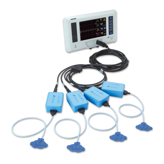
Compare the packing list with the accessories received to make sure the shipment is complete. The monitor includes these non-sterile components: • 7600, Regional Oximeter Monitor (figure 1) • 7600TC-1, Two-Channel Trunk Cable • 7600B or 7600PA, Regional Oximeter Pods (qty 2) •... -
Page 17: Sensor Application
Introduction to the Model 7600 Detail A: Pod (oximeter) with Sensor Display Trunk Cable Pods (contain oximeter) Detail A illustrates sensor to pod connec Figure 2: Setting Up the Monitor (Two-Channel Trunk Cable Shown) Sensor Application Refer to the sensor Instructions for Use (IFU) for proper sensor application sites, and sensor application cautions and warnings. -
Page 18: Bluetooth Technology
Bluetooth-enabled device. Nonin’s wireless system removes the connection from the monitor to a remote monitor location, giving increased ability to move the monitor freely. Nonin’s 7600 monitor uses an automatically switchable class I/class II Bluetooth radio with a maximum range of about 100 meters (328 feet) (spherical radius). -
Page 19: Displays, Indicators, And Controls
Trendline Areas Blue Soft Buttons Speaker AC Power Adapter LED On/Standby Trunk Connector Button Figure 3: Model 7600 Controls and Indicators with Two-Channel Display Channel Displays Channel 1 & 2 Trendline Area Timescale Channel 3 & 4 Trendline Area Figure 4: Four-Channel Display... -
Page 20: Displays
Displays, Indicators, and Controls Displays %rSO Displays The rSO displays, located on the right side of the 7600 monitor front panel, show %rSO blood oxygen saturation from 0 to 100%. The device continually displays an rSO trendline for each monitored channel. The numeric display flashes: •... -
Page 21: Indicators And Controls
AC Power Adapter LED This light-emitting diode (LED) indicator is lit when an external power supply is providing power to the Model 7600. It is YELLOW when the battery pack is charging and GREEN when the battery pack is fully charged. -
Page 22: Table 6. Front Panel Buttons
Pressing this button once turns on the Model 7600. When on, pressing this button for at least 1 second shuts down the 7600, putting it into Standby mode. In Standby mode, all device functions are shut off, with the following exceptions: •... -
Page 23: Figure 5. Model 7600 Main Menu Screen Buttons
Displays, Indicators, and Controls Event Marker Limits Menu Bluetooth Figure 5: Model 7600 Main Menu Screen Buttons Table 7: Main Menu Buttons Symbol Description Event Marker Pressing this button marks an event in memory and on the trendline. Events are denoted by increasing alphabetic letters. -
Page 24: Figure 6. Model 7600 Limits Menu Screen Buttons
Displays, Indicators, and Controls Plus Minus Next Save Figure 6: Model 7600 Limits Menu Screen Buttons Table 8: Limits Menu Buttons Symbol Description Plus (+) and Minus (-) These buttons adjust values for time, date, volume, and upper and lower alarm limits. -
Page 25: Using The Model 7600 Regional Oximeter Monitor
Monitor NOTES: • Before using the Model 7600, please review all contraindications, warnings, and cautions. • Before using the Model 7600 for the first time, the battery should be charged for 4 hours. Verifying System Operation Press ON/STANDBY . Each time the unit is turned on, the 7600 performs a brief initialization sequence: The LCD display lights up and displays the Nonin logo. -
Page 26: Event Mark
Using the Model 7600 Regional Oximeter Monitor How to Determine the Bluetooth Information for the Model 7600 To enter the Bluetooth screen, press the Bluetooth soft button. Note the Bluetooth address on the screen. This address must be chosen at the host computer. -
Page 27: Operating Modes And Defaults
Operating Modes and Defaults Operating Modes and Defaults The Model 7600 features Limits mode, Menu mode, User-Defined Defaults, and Factory Defaults. Limits Mode In Limits mode, users can adjust alarm limits and review limits settings. Pressing the Limits button activates Limits mode. All adjustments... -
Page 28: Reviewing, Setting, Or Changing Alarm Limits
Operating Modes and Defaults Reviewing, Setting, or Changing Alarm Limits How to Set Limits Press Limits Press Next to move through the limits to the limit setting to be changed. Use Plus (+) and Minus (-) to adjust the limit setting. Use Next to move through the limits to the next setting to be changed. -
Page 29: Menu Mode
In Menu Mode, the user may change the trendline selection, timescale, alarm volume, screen brightness, date and time and clear the memory. Figure 9: Model 7600 Menu Mode Screen How to Change Trendline Selection Changing trendline selection allows users to show and hide trendlines for past rSO on the display. - Page 30 Operating Modes and Defaults How to Change Display Timescale Display Timescale is the range of data time displayed on the screen. This setting does not affect stored data. Press Menu Press Next to move through the settings and select “Timescale.” Press Plus (+) or Minus (-) to change the Timescale to the desired setting.
-
Page 31: User Menu Mode
Operating Modes and Defaults How to Clear Memory Press Menu Press Next to move through the settings and select “Clear Memory.” Default setting is NO. Press Plus (+) or Minus (-) to select YES. Press Save Device asks “Clearing memory. Are you sure?” Press Plus (+) or Minus (-) to select YES. -
Page 32: Factory Defaults
Factory Defaults In Factory Defaults, alarm limits are set as indicated in table 10. These are the Model 7600’s default operating settings. The Model 7600 is shipped with factory defaults active. User-Defined Default values are lost when Factory Defaults are NOTE: set active. -
Page 33: User-Defined Defaults
Operating Modes and Defaults User-Defined Defaults The Model 7600 recalls User-Defined Default settings at startup whenever this option is selected. Once they are activated, these settings have priority over Factory Defaults. In User-Defined Defaults, default alarm limit and volume settings may be set to any value. -
Page 34: Nurse Call Feature
NOTE: It is the user’s responsibility to implement the interface between NOTE: the Nurse Call system and the Model 7600, and to adequately test the interface between the Model 7600 and the Nurse Call system to ensure operation. The device Nurse Call and Bluetooth features should WARNING: not be used as the primary source of alarm notification. -
Page 35: Language Options
Operating Modes and Defaults Language Options This feature allows the user to change the language displayed on the monitor. Language options are: • EN - English • FR - French • DE - German • NL - D utch • IT - Italian •... -
Page 36: Alarms
Alarms Alarms The Model 7600 has audio and visual alarm indicators to alert the operator in case immediate patient attention is required or an equipment alarm occurs. High Priority Alarms High priority alarms require immediate attention to the patient. They include high and low rSO alarms. -
Page 37: Silencing Alarms
To correct error conditions, perform these steps: Turn the unit off and then back on again to remove the error code. If the error persists, note the error code and contact Nonin Technical Service at (800) 356-8874 (USA and Canada) or +1 (763) 553-9968. -
Page 38: Memory And Data Output Features
7600 monitor (figure 11). Figure 11: RS-232 Serial Data Port Use only a null modem serial cable to connect the Model 7600 to a NOTE: Verify Bluetooth status as follows: The Bluetooth symbol is green... -
Page 39: Table 13. Data Output Format
Memory and Data Output Features Table 13: Data Output Format Following Parameter Value Delimiter Ch1=XXX Channel 1 regional oximeter value. space Leading zeros blank; --- if no value available. Ch2=XXX Channel 2 regional oximeter value. space Leading zeros blank; --- if no value available. Ch3=XXX Channel 3 regional oximeter value. - Page 40 Memory and Data Output Features Following Parameter Value Delimiter POD_COMM_ALM=x,x,x,x Pod communication alarm indication for channels 1,2,3,4. 0 = no active alarm; 1 = active alarm. SNS_FLT=x,x,x,x Sensor fault indication for channels 1,2,3,4. 0 = no active alarm; 1 = active alarm. LCD_FLT=x Display fault indicator.
-
Page 41: Memory Features
Management Software. During memory download, DATAXFR displays on the 7600 monitor. Each data record in the Model 7600 system is identified by date and time. On a host computer, files are identified by this data, extracted, and stored as either raw data or as a .pdf. The files comply with standards defined in the STS National Adult Cardiac Surgery Database. -
Page 42: Care And Maintenance
Field repair of the Model 7600 is not possible. Do not attempt to open the Model 7600 case or repair the electronics. Opening the case may damage the Model 7600 and void the warranty. If the Model 7600 is not functioning properly, see “Troubleshooting.”... -
Page 43: Parts And Accessories
Parts and Accessories Parts and Accessories The following Nonin accessories function with the Model 7600. Detailed information regarding specified sensor use (patient population and application) can be found in the respective sensor instructions. Model Number Description 7800 PS Power supply, 25W 7600 Manual Operator’s Manual for the Model 7600... - Page 44 Parts and Accessories For more information about Nonin parts and accessories, contact your distributor, or contact Nonin at (800) 356-8874 (USA and Canada) or +1 (763) 553-9968. This information is also available on Nonin’s website: www.nonin.com. Use the Model 7600 only with power adapters supplied WARNING: by Nonin Medical.
-
Page 45: Troubleshooting
Ensure both emitters flash red on new sensor. The 7600B/7600PA is Turn the 7600 off and then back on damaged. again. Observe the start up screen where the software revisions display. Verify a number (1 - 4) appears for the channel that the sensor is connected to. - Page 46 Philips monitor for several seconds and turn on again. If problem persists, contact Nonin Technical Service. If these solutions do not correct the problem, please contact Nonin Technical Service at (800) 356-8874 (USA and Canada) or +1 (763) 553-9968.
-
Page 47: Service, Support, And Warranty
Service, Support, and Warranty Service, Support, and Warranty Service and Support A return authorization number is required before returning any product to Nonin. To obtain this return authorization number, contact Nonin Technical Service: Nonin Medical, Inc. 13700 1st Avenue North... -
Page 48: Warranty
This warranty excludes cost of delivery to and from NONIN. All repaired units shall be received by the purchaser at NONIN's place of business. NONIN reserves the right to charge a fee for a warranty repair request on any device that is found to be within specifications. -
Page 49: Technical Information
Technical Information Technical Information This product complies with ISO 10993, Biological Evaluation of NOTE: Medical Devices Part 1: Evaluation and Testing. A functional tester cannot be used to assess the CAUTION: accuracy of the oximeter monitor or sensor. Portable and mobile RF communications equipment CAUTION: can affect medical electrical equipment. -
Page 50: Table 15. Electromagnetic Immunity
Technical Information Table 15: Electromagnetic Immunity Electromagnetic Immunity IEC 60601 Compliance Environment— Test Test Level Level Guidance This device is intended for use in the electromagnetic environment specified below. The user of this device should ensure that it is used in such an environment. -
Page 51: Table 16. Guidance And Manufacturer's Declaration- Electromagnetic Immunity
Technical Information Table 16: Guidance and Manufacturer’s Declaration— Electromagnetic Immunity Immunity 60601 Compliance Electromagnetic Test Test Level Environment—Guidance Level This device is intended for use in the electromagnetic environment specified below. The user of this device should ensure that it is used in such an environment. Portable and mobile RF communications equipment should be used no closer to any part of the device, including cables, than the recommended separation distance calculated from the equation applicable to the frequency of the transmitter. -
Page 52: Table 17. Recommended Separation Distances
Technical Information Table 17: Recommended Separation Distances This table details the recommended separation distances between portable and mobile RF communications equipment and this device. This device is intended for use in an electromagnetic environment in which radiated RF disturbances are controlled. Users of this device can help prevent electromagnetic interference by maintaining a minimum distance between portable and mobile RF communication equipment (transmitters) and the device as recommended below, according to maximum output power of the... -
Page 53: Testing Summary
Technical Information Testing Summary Principles of Operation Model 7600 oximeter pod uses calculations based on the Beer-Lambert law or Beer’s law, to determine regional oxygenation. The Beer-Lambert law relates the absorption of light to the properties of the material through which the light is traveling. -
Page 54: Specifications
Recharge Time to 90% Capacity: 2.5 hours maximum Dimensions: 7600: Approximately 305 mm (12.0 in.) W x 180 mm (7.2 in.) H x 130 mm (5.0 in.) D 7600B / 7600PA: Approximately 85 mm (3.25 in.) W x 30 mm (1.25 in.) H x 60 mm (2.25 in.) D... -
Page 55: Transmitter
Technical Information Transmitter Version 2.0 Bluetooth Compliance: 2.4 to 2.4835 GHz Operating Frequency: < 20 dBm Output Power: 100-meter (328-feet) radius indoors (line Operating Range: of sight when connected to a class I device) Star Network Topology: Bluetooth Slave Operation: Internal Antenna Type:... -
Page 56: External Monitor Installation Instructions
External Monitor Installation Instructions External Monitor Installation Instructions Philips VueLink Components • Nonin Model 7600 4-Channel Regional Oximeter with RS-232 Serial Data Port • Philips IntelliVue™ Patient Monitoring System (MP40/50/60/70/90, MX800) • Philips M1032A#A05 VueLink Interface Module Auxiliary Plus (Type B) with Digital Open Interface Driver (Philips P/N M1032-60605) •... -
Page 57: Figure 12. 7600 Connection To Philips Monitor
7600, but cannot remotely control the 7600. • Due to the specific features of the VueLink Open Interface Protocol, the data transmission from the 7600 to a Philips monitor may be delayed by several seconds. - Page 58 Module (see figure 12). Connect the VueLink connection cable to the RS-232 serial data port on the back of the 7600. Use the screws to secure the cable to the serial data port. RS-232 extension cables should not be used.
-
Page 59: Figure 13. Philips Indicator On 7600 Display
External Monitor Installation Instructions Communication between the 7600 and Philips monitor should be established within approximately 45 seconds. Once established, PHILIPS displays on the right side of the 7600 LCD (figure 13). Philips indicator Figure 13: Philips Indicator on Model 7600 Display Philips Monitor Display Configuration Nonin’s 7600 rSO... - Page 60 External Monitor Installation Instructions Setup Philips Monitor to Display 7600 Numerics Connect the 7600 to the Philips monitor (see the “Setting up the Connection” section). Verify the 7600 and Philips monitors are on. On the Philips monitor, enter Configuration Mode by selecting Main Setup key.
-
Page 61: Alerts
External Monitor Installation Instructions 15. Philips monitor stores active values as user defaults. 16. Close Setup NONIN 7600 window. 17. Close Measurements window. 18. Close Main Setup window. 19. To place a numeric on the Philips monitor: a. Select the appropriate screen configuration for the Philips... -
Page 62: Table 18. Philips Monitor Patient Alarms
• Numeric flashes • ***rSO HIGH displays • Alarm indicator flashes red Low Limit Yellow • Numeric flashes Warning • **rSO LOW WARN displays • Alarm indicator flashes yellow For more information on 7600 alarms, see the “Alarms” chapter. NOTE:... -
Page 63: Table 19. Philips Monitor Equipment Alarms
Inop messages are green. For more information on Philips monitor equipment alarms, see the specific monitor’s documentation. Table 19: Philips Monitor Equipment Alarms 7600 Alarm Effect on Philips Display (Medium Priority) Pod Communication Error • -?- replaces numeric data •...
Need help?
Do you have a question about the 7600 and is the answer not in the manual?
Questions and answers