Table of Contents
Advertisement
Available languages
Available languages
Quick Links
ENGLISH (Translated from Italian)
A
INDEX
E.2 ELECTRICAL SPECIFICATIONS
A
Index
H.1 Disposal
B
Machine and manufacturer identification
H.2 Preliminary inspection
C
Declaration of incorporation
of
H.3 Positioning the pump
PUMP MODEL
partly-completed Machinery
H.4 Connecting the tubing
D
Machine description
H.5 Considerations regarding
E
Technical specifications
delivery and suction lines
E80 M
E.1 Performance specifications
H.6 Line accessories
E.2 Electrical specifications
H.7 Electrical connections
E120 M
F
Operating conditions
I
Initial start-up
E80 T
F.1 Environmental conditions
L
Daily Use
F.2 Electrical power supply
M
Problems and solutions
E120 T
F.3 Working cycle
N
Maintenance
F.4 Fluids permitted / Fluids not permitted
O
Noise level
E80 110V
G
Moving and transport
P
Exploded diagrams
E120 110V
H
Installation
Q
Dimensions and weights
(*) Refers to functioning with maximum back pressure.
B
MACHINE AND MANUFACTURER IDENTIFCATION
F
OPERATING CONDITIONS
Available Models:
• E80
• E120
MANUFACTURER:
PIUSI SPA
F.1 ENVIRONMENTAL CONDITIONS
VIA PACINOTTI Z.I. RANGAVINO
46029 SUZZARA (MN)
TEMPERATURE:
IDENTIFICATION PLATE (EXAMPLE WITH THE FIELDS IDENTIFIED):
min. -20°C / max. +60°C
! WARNING
PIUSI SPA
46029 SUZZARA (MN)
The temperature limits shown apply to the pump components and must be respected
ITALY
to avoid possible damage or malfunction.
PRODUCT
PRODUCTION
000305000
YEAR 2008
CODE
YEAR
MODEL
E80/M
F.2 ELECTRICAL POWER SUPPLY
230 V
50 Hz
500 W
3.5 A
TECHNICAL
DATA
1400 rpm
Condenser: 450V - 16m
F
Depending on the model, the pump must be supplied by a single-phase alternating
current line whose nominal values are shown in the table in Paragraph E.2 - ELECTRICAL
READ INSTRUCTIONS M0064
MANUAL
SPECIFICATIONS..
The maximum acceptable variations from the electrical parameters are:
Voltage:
Always check that the revision level of this manual coincides
! WARNING
Frequency:
with what is shown on the identification plate.
! WARNING
Power from lines with values outside the indicated limits can damage the
C
DECLARATION OF INCORPORATION OF PARTLY-COMPLETED MACHINERY
electrical components.
The undersigned:
PIUSI S.p.A - Via Pacinotti c.m. - z.i.Rangavino
46029 Suzzara (Mantova) - Italy
F.3 WORKING CYCLE
HEREBY STATES under its own responsibility, that the partly-completed machinery:
The pumps are designed for continuous use under conditions of maximum back pressure.
Description:
Machine designed for the transfer of diesel fuel
Model:
E80 - E120
! WARNING
Serial number:
refer to Lot Number shown on CE plate affixed to product
Functioning under by-pass conditions is only allowed for brief periods of time
Year of manufacture: refer to the year of production shown on the CE plate affixed to the
(2-3 minutes maximum).
product
is intended to be incorporated in a machine (or to be with other machines) so as to create a
machine to which applies Machine Directive 2006/42/EC, may not be brought into service before
the machine into which it is to be incorporated has been declared in conformity with the provisions
F.4 FLUIDS PERMITTED / FLUIDS NOT PERMITTED
of the directive 2006/42/EC.
is in conformity with the legal provisions indicated in the directives:
PERMITTED:
- Machine Directive 2006/42/EC
• DIESEL FUEL at a viscosity of from 2 to 5.35 cSt (at a temperature of 37.8°C)
- Low-Voltage Directive 2006/95/EC
Minimum flash point (PM): 55°C
- Electromagnetic Compatibility Directive 2004/108/EC
To which the essential safety requirements have been applied and complied with what indicated
NOT PERMITTED:
on annex I of the machine directive applicable to the product and shown below: 1.1.3 - 1.1.5 - 1.3.1 -
• GASOLINE
1.3.2 - 1.3.3 - 1.3.4 - 1.3.8 - 1.4.1 - 1.4.2.1 - 1.5.1 - 1.5.2 - 1.5.4 - 1.5.5 - 1.5.8 - 1.5.11 - 1.6.1 - 1.6.3 -
1.6.4 - 1.7.1 - 1.7.2 - 1.7.3 - 1.7.4.
• INFLAMMABLE LIQUIDS WITH PM < 55°C
• LIQUIDS WITH VISCOSITY > 20 cSt
The documentation is at the disposal of the competent authority following motivated request at Piusi
• WATER
S.p.A. or following request sent to the email address: doc_tec@piusi.com
• FOOD LIQUIDS
The person authorised to compile the technical file and draw up
the declaration is Otto Varini as legal representative.
• CORROSIVE CHEMICAL PRODUCTS
Suzzara, 29/12/2009
• SOLVENTS
the legal representative
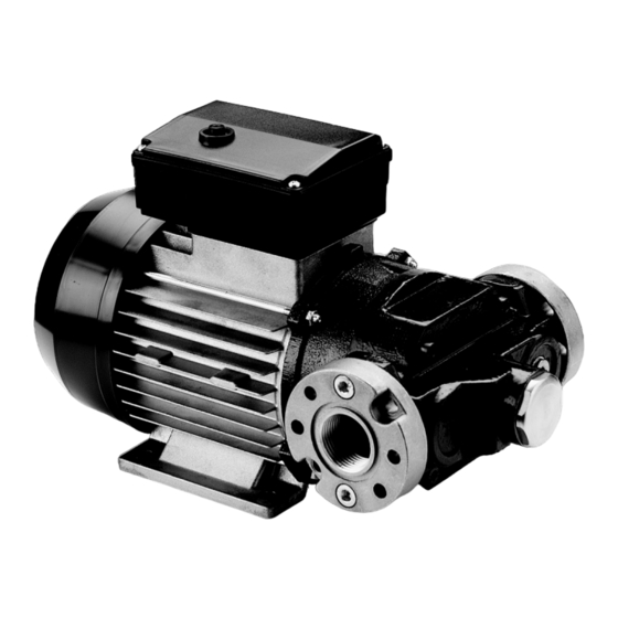
D
MACHINE DESCRIPTION
G
MOVING AND TRANSPORT
Given the limited weight and size of the pumps (see overall dimensions), moving the pumps
PUMP:
Self-Priming, volumetric, rotating electric vane pump, equipped with by-pass
does not require the use of lifting devices.
valve.
The pumps were carefully packed before shipment.
Check the packing material on delivery and store in a dry place.
MOTOR:
Asynchronous motor, single-phase and three-phase, 4 pole, closed type (protection
class IP55 in conformance with EN 60034-5-86 regulations) self-ventilated, directly
flanged to the pump body.
H
INSTALLATION
E
TECHNICAL SPECIFICATIONS
H.1 DISPOSAL
E.1 PERFORMANCE SPECIFICATIONS
The components must be given to companies that specialise in the disposal and recycling of
industrial waste and, in particular, the
The performance diagram shows flow rate as a function of back pressure.
DISPOSAL OF PACKAGING:
Typical delivery configuration
The packaging consists of biodegradable cardboard which can be delivered to companies for
normal recycling of cellulose.
DISPOSAL OF METAL COMPONENTS:
Metal parts, whether paint-finished or in stainless steel, can be consigned to scrap metal
Functioning
Back
Model
Flow rate
collectors.
point
pressure
DISPOSAL OF ELECTRIC AND ELECTRONIC COMPONENTS:
these have to be disposed by companies that are specialised in the disposal of electronic
components, in accordance with the instructions of 2002/96/EC (see text of Directive below).
ENVIRONMENTAL INFORMATION FOR CUSTOMERS IN THE EUROPEAN
A
E 80
80
0.6
UNION
(Maximum
flow rate)
E 120
110
0.5
B
E 80
75
1.9
(Maximum
back
E 120
105
2.5
pressure)
E 80
0
2.2
C
DISPOSAL OF OTHER PARTS:
Delivery closed
The disposal of other parts such as pipes, rubber seals, plastic components and cables should
(Bypass)
E 120
0
2.8
be entrusted to companies that special in the disposal of industrial waste.
DISPOSAL OF PACKAGING:
A
B
The packing material does not require special precautions for its disposal, not being in any way
dangerous or polluting. Refer to local regulations for its disposal.
H.2 PRELIMINARY INSPECTION
•
Check that the machine has not suffered any damage during transport or storage.
•
Make sure that the motor shaft turns freely.
•
Clean the inlet and outlet openings, removing any dust or residual packing material.
C
•
Check that the electrical specifications correspond to those shown on the identification plate.
Back pressure
! WARNING
H.3 POSITIONING THE PUMP
The curve refers to the following operating conditions:
Fluid:
Diesel fuel
•
The pump can be installed in any position (pump axis vertical or horizontal).
Temperature:
20°C
Suction conditions:
The tube and the pump position relative to the fluid level is
•
Attach the pump using screws of adequate diameter for the attachment holes provided in
such that a pressure of 0.3 bar is generated at the nominal
the base of the pump (see the section "OVERALL DIMENSIONS" for their position and
flow rate.
dimension).
Under different suction conditions higher pressure values can be created that reduce
the flow rate compared to the same back pressure values.
! WARNING
To obtain the best performance, it is very important to reduce loss of suction
pressure as much as possible by following these instructions:
THE MOTORS ARE NOT OF AN ANTI-EXPLOSIVE TYPE.
• Shorten the suction tube as much as possible
Do not install them where inflammable vapors can be present.
• Avoid useless elbows or throttling in the tubes
• Keep the suction filter clean
• Use a tube with a diameter equal to, or greater than, indicated (see Installation)
ENGLISH (Translated from Italian)
ENGLISH (Translated from Italian)
H.4 CONNECTING THE TUBING
•
Before connection, make sure that the tubing and the suction tank are free of dirt and thread
ELECTRICAL POWER
CURRENT
residue that could damage the pump and its accessories.
Voltage
Frequency
Max. absorption (*)
•
Before connecting the delivery tube, partially fill the pump body with diesel fuel to facilitate
Current
(V)
(Hz)
(Amp)
priming.
•
Do not use conical threaded joints that could damage the threaded pump openings if
AC
230
50
3.5
excessively tightened.
AC
230
50
6
SUCTION TUBING
AC
400
50
1.6
- Minimum recommended nominal diameter:
AC
400
50
2.5
- Nominal recommended pressure:
AC
110
60
10
- Use tubing suitable for functioning under suction pressure
AC
110
60
9.5
DELIVERY TUBING
- Minimum recommended nominal diameter:
- Nominal recommended pressure:
! WARNING
It is the installer's responsibility to use tubing with adequate characteristics.
RELATIVE HUMIDITY:
The use of tubing unsuitable for use with Diesel fuel can damage the pump, injure
max. 90%
persons and cause pollution.
Loosening of the connections (threaded connections, flanging, gasket seals) can
cause serious ecological and safety problems..
Check all the connections after the initial installation and on a daily basis after that.
Tighten the connections, if necessary.
H.5 CONSIDERATIONS REGARDING DELIVERY AND SUCTION LINES
DELIVERY
The choice of pump model must be made keeping the characteristics of the system in mind.
The combination of the length of the tubing, the diameter of the tubing, the flow rate of the
+/- 5% of the nominal value
diesel fuel and the line accessories installed can create back pressure greater than the
+/- 2% of the nominal value
maximums anticipated such as to cause the (partial) opening of the pump by-pass with the
consequent noticeable reduction of the flow rate supplied.
In such cases, to allow correct functioning of the pump, it is necessary to reduce system
resistance, using shorter tubing and/or of wider diameter and line accessories with less
resistance (e.g., an automatic dispensing nozzle for greater flow rates).
SUCTION
E 80 / E120 pumps are self-priming and characterized by good suction capacity.
During the start-up phase, with an empty suction tube and the pump wetted with fluid, the electric
pump unit is capable of suctioning the liquid with a maximum difference in height of 2 meters.
It is important to point out that the priming time can be as long as one minute and the presence
of an automatic dispensing nozzle on the delivery line prevents the evacuation of air from the
installation, and, therefore, prevents proper priming.
For this reason, it is always advisable to prime the pump without an automatic delivery nozzle,
verifying the proper wetting of the pump. The installation of a foot valve is recommended to
prevent the emptying of the suction tube and keep the pump wet. In this way, the pump will
subsequently always start up immediately.
When the system is functioning, the pump can work with pressure at the inlet as high as
0.5 bar, beyond which cavitation phenomena can begin, with a consequent loss of flow rate
and increase of system noise.
As we have said up to this point, it is important to guarantee low suction pressure by using
short tubing of a diameter equal to or larger than recommended, reducing curves to a
RELATED DANGERS:
minimum and using suction filters of wide cross-section and foot valves with the lowest
possible resistance.
• FIRE - EXPLOSION
It is very important to keep the suction filters clean because, once clogged, they increase
• FIRE - EXPLOSION
system resistance.
• MOTOR OVERLOAD
The difference in height between the pump and the fluid level must be kept as small as possible
• PUMP OXIDATION
and, at any rate, within the 2 meters anticipated for the priming phase.
• CONTAMINATION OF THE SAME
If this height is exceeded, it will always be necessary to install a foot valve to allow for the filling of
• PUMP CORROSION
the suction tube and provide tubing of wider diameter. It is recommended that the pump not be
INJURY TO PERSONS
installed at a difference in height greater than 3 meters.
• FIRE - EXPLOSION
DAMAGE TO GASKET SEALS
! WARNING
In the case that the suction tank is higher than the pump, it is advisable to install
an antisiphon components.
H.6 LINE ACCESSORIES
The pumps are furnished without line accessories. Following is a list of the most common line
accessories whose use is compatible with the proper functioning of the pumps.
DELIVERY:
• Automatic dispensing nozzle
• Manual dispensing nozzle
• Meter
• Flexible tubing
! WARNING
It is the installer's responsibility to provide the line accessories necessary for the safe
and proper functioning of the pump.
The use of accessories unsuitable for use with diesel fuel can damage the pump,
injure persons and cause pollution..
! WARNING
IT IS THE INSTALLER'S RESPONSIBILITY TO APPLY THE
FOLLOWING SIGNALS ON THE MACHINE ANYWHERE
E80/E120 WILL BE USED:
European Directive 2002/96/EC requires that the equipment bearing this symbol
H.7 COLLEGAMENTI ELETTRICI
on the product and/or its packaging must not be disposed of with unsorted
municipal waste. The symbol indicates that this product should be disposed of
separately from regular household waste streams.
SINGLE-PHASE MOTORS
It is your responsibility to dispose of this and other electric and electronic
equipment via designated collection facilities appointed by the government or
Single-phase motors are supplied with a pre-existing 2-meter cable with electric plug.
local authorities.
To change the cable, open the terminal strip cover and connect the line according to the
following diagram:
THREE PHASE
A.C. LINE
Single-phase motors are supplied with a bipolar switch and capacitor wired and installed
inside the terminal strip box (see diagram).
The characteristics of the capacitor are shown on the identification plate for each pump model.
The switch has the sole function of starting/stopping the pump and cannot in any way substitute
for the main circuit breaker provided for in the applicable regulations.
! WARNING
The pumps are supplied without electrical safety equipment such as fuses, motor
protectors, systems to prevent accidental restarting after power failures or others.
It is indispensable to install an electric panel, upstream from the pump's power supply
line, equipped with an appropriate residual current operated circuit breaker.
It is the installer's responsibility to perform the electrical connections with respect
for the applicable regulations.
ENGLISH (Translated from Italian)
THREE-PHASE MOTORS
Three-phase motors are supplied with a terminal strip box and terminal strip.
To connect the electric motor to the electric power line, open the terminal strip cover and
connect the cables according to the diagram.
! WARNING
Verify that the terminal strip blades are positioned according to the diagram provided
for the available power supply voltage.
Verify the correct direction of rotation of the motor (see the paragraph OVERALL
1-1/4" (model E80)
DIMENSIONS), and, if not correct, invert the connection of the two cables in the
1-1/2" (model E120)
power supply plug or on the terminal strip.
10 bar
Respect the following (not exhaustive) instructions to ensure a proper electrical
installation:
•
During installation and maintenance, make sure that the electric supply lines are not live.
1"
10 bar
•
Use cables characterized by the minimum cross-sections, nominal voltages and wiring-type
adequate to the electrical characteristics shown in Paragraph E.2 - ELECTRICAL
SPECIFICATIONS and the installation environment..
•
In three-phase motors verify the correct direction of rotation (see Paragraph Q - DIMENSIONS
AND WEIGHTS).
•
All motors are equipped with a ground terminal to connect to the ground line of the
electrical network.
•
Always close the cover of the terminal strip box before supplying electrical power,
after ascertaining the integrity of the gasket seals that ensure protection
grade IP 55.
I
INITIAL START-UP
•
Check that the quantity of diesel fuel in the suction tank is greater than the amount you
wish to transfer.
•
Make sure that the residual capacity of the delivery tank is greater than the quantity you
wish to transfer.
•
Do not run the pump dry. This can cause serious damage to its components.
•
Make sure that the tubing and line accessories are in good condition. Diesel fuel leaks
can damage objects and injure persons.
•
Always install a suction filter to protect the pump.
•
Never start or stop the pump by inserting or removing any plugs.
•
Do not operate switches with wet hands.
•
Prolonged contact with diesel fuel can damage the skin. The use of glasses and gloves
is recommended.
•
Single-phase motors are provided with an automatic thermal protection switch.
! WARNING
Extreme operating conditions can raise the motor temperature and, consequently,
cause the thermal protection switch to stop it.
Turn off the pump and wait for it to cool before resuming use.
The thermal protection automatically turns off when the motor is sufficiently cool.
In the priming phase the pump must blow the air initially present in the entire installation out of
the delivery line.
Therefore it is necessary to keep the outlet open to permit the evacuation of the air.
! WARNING
If an automatic type dispensing nozzle is installed on the end of the delivery line,
the evacuation of the air will be difficult because of the automatic stopping device that
keeps the valve closed when the line pressure is too low.
It is recommended that the automatic dispensing nozzle be temporarily disconnected
during the initial start-up phase.
The priming phase can last from several seconds to a few minutes, as a function of
the characteristics of the system.
If this phase is prolonged, stop the pump and verify:
•
That the pump is not running completely dry;
•
That the suction tubing is not allowing air to seep in;
•
That the suction filter is not clogged;
•
That the suction height is not greater than 2 meters (if the height is greater than 2 meters,
fill the suction tube with fluid);
•
That the delivery tube is allowing the evacuation of the air.
SUCTION:
When priming has occurred, verify that the pump is operating within the anticipated range,
• Foot valve with filter
in particular:
• Rigid and flexible tubing
• Pump suction filter
•
That under conditions of maximum back pressure, the power absorption of the motor
stays within the values shown on the identification plate;
•
That the suction pressure is not greater than 0.5 bar;
•
That the back pressure in the delivery line is not greater than the maximum back pressure
anticipated for the pump.
L
DAILY USE
a.
If using flexible tubing, attach the ends of the tubing to the tanks. In the absence
of an appropriate slot, solidly grasp the delivery tube before beginning
dispensing.
b.
Before starting the pump make sure that the delivery valve is closed (dispensing nozzle
or line valve).
c.
Turn the ON/OFF switch to ON. The by-pass valve allows functioning with the delivery closed
for only brief periods.
d.
Open the delivery valve, solidly grasping the end of the tubing.
e.
Close the delivery valve to stop dispensing.
f.
When dispensing is finished, turn off the pump.
! WARNING
Functioning with the delivery closed is only allowed for brief periods (2-3 minutes
SINGLE PHASE
maximum). After use, make sure the pump is turned off.
TO MOTOR
LACK OF ELECTRIC POWER:
A lack of electric power, with the consequent accidental stopping of the pump, can be caused
by:
- A safety device tripping
- A drop in line voltage
In either case, act as follows:
TO
a.
Close the delivery valve
MOTOR
b.
Attach the end of the delivery to the slot provided on the tank
c.
Turn the ON/OFF switch to the OFF position.
Resume operations as described in Paragraph L - DAILY USE, after determining the cause
of the stoppage.
Bulletin
ENGLISH (Translated from Italian)
MOO64C
IT/EN
M
PROBLEMS AND SOLUTIONS
Rev. 1
PROBLEM
POSSIBLE CAUSE
CORRECTIVE ACTION
Check the electrical
Lack of electric power
connections and the safety
systems
Check for possible damage or
Rotor jammed
obstruction of the rotating
components
THE MOTOR
IS NOT TURNING
Wait for the motor to cool,
The motor protecting thermal
verify that it restarts, and
switch has tripped
research the cause of the
overheating
Contact the Service
Motor problems
Department
THE MOTOR
Low voltage in the electric
Bring the voltage back within
TURNS SLOWLY
power line
the anticipated limits
WHEN STARTING
Low level in the suction tank
Refill the tank
Foot valve blocked
Clean and/or replace the valve
Filter clogged
Clean the filter
Lower the pump with respect
to the level of the tank or
Excessive suction pressure
increase the cross-section
of the tubing
High loss of head in the
Use shorter tubing or of greater
circuit (working with the
diameter
by-pass open)
LOW OR NO
FLOW RATE
Dismantle the valve, clean
By-pass valve blocked
and/or replace it
Air entering the pump or the
Check the seals of the
suction tubing
connections
A narrowing in the suction
Use tubing suitable for working
tubing
under suction pressure
Check the voltage at the pump;
Low rotation speed
Adjust the voltage and/or use
cables of greater cross-section
The suction tubing is resting on
Raise the tubing
the bottom of the tank
Cavitation occurring
Reduce suction pressure
INCREASED
Irregular functioning of the
Dispense until the air is purged
PUMP NOISE
by-pass
from the circuit
Air present in the diesel fuel
Verify the suction connections
LEAKAGE FROM THE
Check and replace the
Seal damaged
PUMP BODY
mechanical seal
N
MAINTENANCE
E 80 / E 120 pumps are designed and constructed to require a minimum of
maintenance.
•
On a weekly basis, check that the tubing joints have not loosened, to avoid any leakage.
•
On a monthly basis, check the pump body and keep it clean of any impurities.
•
On a monthly basis, check and keep the pump filter clean and any other filters installed.
•
On a monthly basis, check that the electric power supply cables are in good condition.
O
NOISE LEVEL
Under normal working conditions the noise emission from all models does not exceed the value
of 70 dB at a distance of 1 meter from the electric pump.
Bulletin M0064C IT/EN - Rev.1
MANUALE
D'USO E
ITALIANO
MANUTENZIONE
USE AND
MAINTENANCE
ENGLISH
MANUAL
Copyright
Advertisement
Table of Contents

Subscribe to Our Youtube Channel
Related Manuals for Piusi E120


Summary of Contents for Piusi E120
- Page 1 • LIQUIDS WITH VISCOSITY > 20 cSt • MOTOR OVERLOAD The documentation is at the disposal of the competent authority following motivated request at Piusi If an automatic type dispensing nozzle is installed on the end of the delivery line, The difference in height between the pump and the fluid level must be kept as small as possible •...
- Page 2 DICHIARA sotto la propria responsabilità, che la quasi macchina: Le pompe E80 / E120 sono autoadescanti e caratterizzate da una buona capacità di • Un prolungato contatto della pelle con il gasolio può provocare danni. L'utilizzo di occhiali e aspirazione.
Need help?
Do you have a question about the E120 and is the answer not in the manual?
Questions and answers