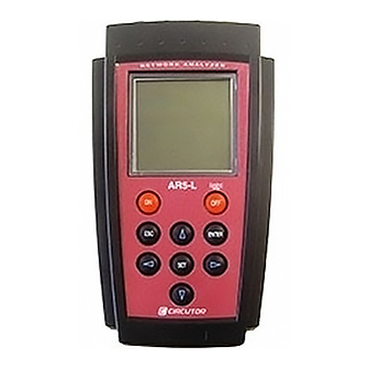
Circutor AR5-L Instruction Manual
Supply network analyzer
Hide thumbs
Also See for AR5-L:
- Instruction manual (51 pages) ,
- Instruction manual (20 pages) ,
- Quick start manual (9 pages)

Subscribe to Our Youtube Channel
Related Manuals for Circutor AR5-L


Summary of Contents for Circutor AR5-L
- Page 1 SUPPLY NETWORK ANALYZER AR5-L ( Code M 80111 ) (CHECK-METER Program) ( Cod. M 80225 ) INSTRUCTION MANUAL ( M98110301-03-04A ) CIRCUTOR S.A.
-
Page 2: Table Of Contents
5.4.- FILES Menu ..................18 5.4.1.- DIR: Directory ................18 5.4.2.- DELETE: Deleting a file ............... 18 5.4.3.- FORMAT: Formatting the AR5-L internal memory ....... 19 5.5.- Menu OFF: Enable / Disable Password..........19 5.6.- Menu LANGUAGE ................19... - Page 3 AR5-L COMMUNICATIONS ............... 28 TECHNICAL SPECIFICATIONS............29 SAFETY WARNINGS ................. 31 10.- MAINTENANCE.................. 31 11.- TECHNICAL SERVICE............... 31 CABLE ARRANGEMENT ..............32 QUICK GUIDE (AR5-L) ................. 33 C. QUICK GUIDE FOR AR5 - CHECK-METER......... 33 D. EXAMPLE OF TRANSFORMATION RELATIONS ........ 34...
-
Page 4: Basic Instructions
1.3.- Connection instructions Before powering and connecting the analyzer check the following points: a) Supply voltage: Through and external power supplier set. Input mains 80 V a.c. – 265 V a.c. / output to AR5-L 12V d.c. b) Frequency : 45...65 Hz. -
Page 5: Analyzer Startup
(LOAD PROGRAM). Press [ENTER] or wait for a while to confirm this operation. • Select the position to save the program into. • The AR5-L will perform a test to check that the cartridge has been properly connected. • If an inserted cartridge is detected, then the program will be loaded. -
Page 6: Choice Of The Operation Mode Program
Page nº 2.2.- Choice of the operation mode program The AR5-L can hold in memory different operation mode programs. The choice of the program to be used is done when starting the AR5-L up. • Turn the AR5-L on. •... -
Page 7: Connection Modes
-------------- SUPPLY NETWORK ANALYZER AR5-L ----------- Page nº 3.- CONNECTION MODES A.- THREE-PHASE MODE CONNECTION DIAGRAM B.- SINGLE-PHASE MODE CONNECTION DIAGRAM... - Page 8 -------------- SUPPLY NETWORK ANALYZER AR5-L ----------- Page nº C.- ARON MODE CONNECTION DIAGRAM...
-
Page 9: Data Visualization On Display
Energy values are partial values. The value is always reset to zero when accessing this screen. These values are not accumulated. Pressing the key [SET] from this screen m the set-up menu is accessed. When powering the AR5-L on, the display will show: CHECK-METER INST... -
Page 10: Screen For Energy Meter Check
-------------- SUPPLY NETWORK ANALYZER AR5-L ----------- Page nº Inductive reactive power: The inductive reactive power is calculated from instantaneous voltage and current data. The readout gives the instantaneous values of the inductive reactive power of each phase and also the three phase total instantaneous inductive reactive power, which is the addition of each phase value. -
Page 11: Warning Messages
5.6.-). 5.1.- Set-up of Instantaneous Values To accessing AR5-L setup options press the key [SET], on the instantaneous values screen The analyzer will then inquiry for a password that consists of a key sequence to be pressed (the user has 15 seconds to press this sequence). If the... - Page 12 -------------- SUPPLY NETWORK ANALYZER AR5-L ----------- Page nº All programs have an independent setup, therefore, the setup must be always check to ensure a proper operation, since any modification will only affect the active operation program. Diverse setting MENUS are available:...
-
Page 13: Setup Menu
-------------- SUPPLY NETWORK ANALYZER AR5-L ----------- Page nº 5.1.1.- SETUP menu The AR5-L meter can be user-configured to different performances involving its data analysis and recording modes, as it is followed shown: SETUP MEASURE COMM SETUP menu. CLOCK PASSWORD RECALL... -
Page 14: 1.- Wiring: Circuit Type
AR5-L analyzer (Never directly connect the 5 A signal to the AR5-L.). For this case, the C.T. primary must be set at the primary value of the C.T. used for measuring purposes. -
Page 15: Clock: Internal Clock
-------------- SUPPLY NETWORK ANALYZER AR5-L ----------- Page nº Though keys [6], [5] the value of the selected position is increased or decreased. [ENTER] to validate the total value or [ESC] to exit with no modification. 5.1.4.- CLOCK: Internal clock Use this section to set the analyzer internal clock in time: date / time and displaying format. -
Page 16: Recall: Read Configuration
A confirmation is requested: “Recall Setup sure <yes> or <no>“. With keys [4] & [3] select yes or no, and then press [ENTER]. A “Standard” operation program for the AR5-L is available to be user-recalled. Its features are: - C.T. Ratio (SET + A) - V.T. -
Page 17: Display Menu
... 5.2.1.- CONTRAST: Screen contrast The user can here vary the contrast of the AR5-L display: With the [4] you can intensify the display contrast and with the key [3] this can be lowered: CONTRAST 5.2.2.- POWER FACTOR... -
Page 18: Files Menu
Page nº 5.3.- FILES Menu Non-volatile AR5-L internal memory is storing data up to its maximum capacity. Once full, no new data will not be saved in, nor stored data will be lost (provided no incorrect operation is done). When memory is full, the display will show: "MEMORY FULL". -
Page 19: Format: Formatting The Ar5-L Internal Memory
5.4.- Menu OFF: Enable / Disable Password. In order to avoid an accidental manipulation of the analyser, the AR5-L can be set to request for a password when the user wants to turn it off. -
Page 20: Setup For Energy Meter Check
6. RECORD: To save in memory the record of the performed check. 7. This section will show the real value measured by the AR5-L and also the value that the CHECK-METER should have measured according to the user-programmed values (points: 3, 4 &... -
Page 21: Operation Mode
-------------- SUPPLY NETWORK ANALYZER AR5-L ----------- Page nº 6.- Operation mode When checking energy meters it is advisable to: • For any type of energy meter: To perform the energy meter check when the installation is at full operation conditions. The higher the consumption is, the higher the check reliability will be. -
Page 22: Checking Mechanic Energy Meters
-------------- SUPPLY NETWORK ANALYZER AR5-L ----------- Page nº 7.- Checking energy meters 7.1.- Checking mechanic energy meters AR5 CHECK-METER (1) User's data User Name 1/1V 5/5A (2) P.T. and C.T. ratios (3) Check of energy meters TURNS/IMP (4) Check of number turns or pulses... - Page 23 -------------- SUPPLY NETWORK ANALYZER AR5-L ----------- Page nº 7.- During some moments of data recording: 8.- You will see again at the bottom of the screen: STOP 9.- The energy meter checking process will be stopped when pressing again [ENTER].
-
Page 24: Checking Electronic Energy Meters
-------------- SUPPLY NETWORK ANALYZER AR5-L ----------- Page nº 7.2.- Checking electronic energy meters AR5 CHECK-METER (1) User's data User Name 1/1V 5/5A (2) P.T. and C.T. ratios (3) Check of energy meters TURNS/IMP nTURNS? kWh START (5) Check start and end energy test... - Page 25 -------------- SUPPLY NETWORK ANALYZER AR5-L ----------- Page nº 7.- During some moments of data recording 8.- You will see again at the bottom of the screen: STOP 9.- The energy meter checking process will be stopped when pressing again [ENTER].
-
Page 26: Checking Electronic Energy Meters Using The Optical Reader
-------------- SUPPLY NETWORK ANALYZER AR5-L ----------- Page nº 7.3.- Checking electronic energy meters using the optical reader. It is possible to connect an optical reader (ref XXXXXXX) for those meters that have a LED. Connect the optical reader into AUX plugin... - Page 27 Page nº 6.- Connect the optical reader, if it is not connected yet , to the Ar5-l and align optical head with the LED of the meter. 7.- Press [ENTER] to start the energy meter checking process. After requesting a...
-
Page 28: Ar5-L Communications
Perform the connection using the two wires factory-delivered with the AR5-L. One cable will link the AR5-L to the power supplier set, and another cable is a standard RS232 connector. When starting communication tasks take into account: •... -
Page 29: Technical Specifications
-------------- SUPPLY NETWORK ANALYZER AR5-L ----------- Page nº 9.- TECHNICAL SPECIFICATIONS Supply voltage: Through an external power supplier set 230 V a.c. (+10% / -15%) Frequency : 50...60 Hz Burden : 8 VA Operation temperature : 0 / 50 ºC... - Page 30 - 1000 case (with protection rubber CPR-1000) ....CODE M 89923 - 2000 case (with protection rubber CPR-2000) ....CODE M 89921 − Adapters - connector adapter AR5 clamp to AR5L ..……..CODE. M 89927 - Connector adapter AR5-L C-FLEX clamp to AR5-L ..CODE. M 89928...
-
Page 31: Safety Warnings
11.- MAINTENANCE The AR5-L does not require any special maintenance. No adjustment, maintenance or repairing actions should be done over the instrument open and, should those are essential, high-qualified operators must perform them. -
Page 32: Cable Arrangement
-------------- SUPPLY NETWORK ANALYZER AR5-L ----------- Page nº A. CABLE ARRANGEMENT Different cables used with the AR5-L have following arrangements: • Communication cable RS232: PC - Power supplier set POWER SUPPLIER • Power supply/Communication: Power supplier set - AR5-L. POWER... -
Page 33: Quick Guide (Ar5-L)
-------------- SUPPLY NETWORK ANALYZER AR5-L ----------- Page nº B. QUICK GUIDE (AR5-L) Menu Description Options Standard Setup Measure Circuit Choice type of measuring circuit. Three-phase Three-phase Single-phase Tr. Rel Rel. V Voltage transformers ratio. Primary=1 Secondary=1 Rel. A Current transformers ratio. -
Page 34: Example Of Transformation Relations
-------------- SUPPLY NETWORK ANALYZER AR5-L ----------- Page nº D. EXAMPLE OF TRANSFORMATION RELATIONS Clamps connected in the secondary one 27000 V 500 A 110 V 5 A 5A clamps METER CHECK-METER USER 27000/110V 500/5 Clamps connected in the primary one...
Need help?
Do you have a question about the AR5-L and is the answer not in the manual?
Questions and answers