
Subscribe to Our Youtube Channel
Related Manuals for Circutor AR5


Summary of Contents for Circutor AR5
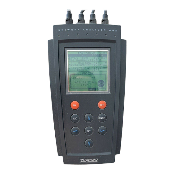
- Page 1 SUPPLY NETWORK ANALYZER AR5 and AR5-L INSTRUCTION MANUAL ( M98151101-03-05A ) CIRCUTOR S.A.
-
Page 2: Table Of Contents
CONTENTS page BASIC INSTRUCTIONS ................ 4 1.1.- Introduction: check the contents of your package ......... 4 1.2.- Safety conditions................... 4 1.3.- Connection instructions................. 4 1.4.- Operation instructions ................5 ANALYZER MAIN FEATURES.............. 6 2.1.- Basic features ..................6 2.2.- Other characteristics ................ - Page 3 PROGRAMMING THE ANALYZER............. 29 6.1.- SETUP menu ..................30 6.1.1.- MEASURE ..................31 6.1.1.1.- WIRING: Circuit type............... 31 6.1.1.2.- PT/CT : Transformation ratios..........31 6.1.2.- RECORD menu ................31 6.1.2.1.- PERIOD: recording period ............32 6.1.2.2.- TRIGGER: Trigger conditions ..........33 6.1.2.3.- NAME: recording file name .............
-
Page 4: Basic Instructions
Connection instructions Before powering and connecting the analyzer check the following points: Supply voltage: Through and external power supplier set. Input mains 100 V a.c. – 240 V a.c. / output to AR5/AR5-L 12V d.c. Frequency : 45...65 Hz. Maximum voltage at the voltage measuring circuit:... -
Page 5: Operation Instructions
Current measuring range: according to the Current clamp used Current clamps Measuring range 10 to 2000 A a.c. (switch at 2000) CP-2000-200 1 to 200 A a.c. (switch at 200) CPR-1000 5 to 1000 A a.c. CPR-500 2,5 to 500 A a.c. CP-100 (M1-U) 0, 5 to 100 A a.c. -
Page 6: Analyzer Main Features
ANALYZER MAIN FEATURES Basic features The AR5 series analyzers are programmable instruments that measure, calculate and store to memory the main parameters of three phase electrical supply networks. Clamp inputs (.. 2 V a.c.). a.c. Voltage inputs Power Supply: 12 V c.c. / Serial input only in AR5-L models Setup: Analyzer’s setting is completed through a system of spreadable menus that provide a friendly-use and... - Page 7 4-wire three-phase system: Parameter Symbol Three-phase value Phase-to-Neutral voltage Current Neutral current (only in AR5-L model) Frequency Active power Reactive power L kvarL Reactive power C kvarC Apparent power Power factor Active energy kW h Reactive-energy (inductive) kvaLh Reactive-energy (capacitive)
- Page 8 Voltage Current Neutral current* Frequency Active power Reactive power L kvarL Reactive power C kvarC Apparent power Power factor Active energy kW h Reactive-energy (inductive) kvahL Reactive-energy (capacitive) kvahC Voltage harmonics Current harmonics Neutral current harmonics *only in AR5-L model...
-
Page 9: Keyboard Functions
1.- KEYBOARD FUNCTIONS The analyzer has a 9 buttons keyboard to perform configuration and control actions of all the instrument options. [ON] to turn the analyzer on. [OFF] (Quick press) to turn on/off the display back-light. [OFF] (5 seconds press) to turn analyzer off. [6], [5], [4] &... -
Page 10: Connection Diagram
Connection diagram A.- CONNECTION DIAGRAM FOR THREE-PHASE - 4-WIRE – SYSTEM This connection is only available for AR5-L model ( SET ---> SETUP ---> MEASURE ---> WIRING ---> 3Φ 4 WIRES) - Page 11 B.- CONNECTION DIAGRAM FOR THREE-PHASE - 3-WIRE - SYSTEM. ( SET ---> SETUP ---> MEASURE ---> WIRING ---> 3Φ 3 WIRES )
- Page 12 C.- CONNECTION DIAGRAM FOR THREE-PHASE - 3-WIRE (ARON) ( SET ---> SETUP ---> MEASURE ---> WIRING ---> 3 PT – 2 CT...
- Page 13 D.- CONNECTION DIAGRAM FOR SINGLE-PHASE - SYSTEM ( SET ---> SETUP ---> MEASURE ---> WIRING ---> 1Φ)
- Page 14 E.- CONNECTION DIAGRAM FOR BI-PHASE - SYSTEM This connection is only available for AR5-L model ( SET ---> SETUP ---> MEASURE ---> WIRING ---> 1Φ Split )
-
Page 15: Starting The Analyzer Up
Starting the analyzer up Before connecting the instrument to the mains, please consider following points: Supply voltage: 100 V a.c. – 240 V a.c. , 50... 60 Hz. The instrument must be energized by a supply circuit with protection earth terminal. Maximum input voltage at the voltage measuring circuit: 500 V a.c. - Page 16 To turn the instrument on: Press the switch <ON> at the analyzer frontal cover. The analyzer introduction screen appears. The user can now select the operation mode program for the analyzer 16) After some seconds, a screen allowing the choice of the analyzer program to be used is shown up. 17) One the desired program has been selected, analyzer will check the type of ammeter clamps connected to the analyzer.
-
Page 17: Loading A New Program
Loading a new program analyzer has an internal memory to save diverse operation mode programs to be used by the user. Before starting this action, check that analyzer is supplied through the power supplier set. To load any program, follow these instructions precisely: Turn the meter off. -
Page 18: Turn The Analyzer Off
Turn the analyzer off To turn the analyzer off proceed as follows: If no password is set (Default option): Press the key [OFF] during 5 s If a password is set: Press the key [OFF] during 5 s You will see in display: PASSWORD Enter the set password or, if this has not been previously modified, the default password [3] [SET] [5] [SET]. -
Page 19: Recharging The Analyzer Battery
Recharging the analyzer battery The analyzer is equipped with an intelligent energy charging system. This means that the instrument continuously checks in an automatic way the state of the battery, thus the charging process stops when the battery is at its maximum charge level. -
Page 20: Data Visualization On Display
Frequency : Readout of the instantaneous value of the frequency (Hz). Neutral Current : Readout the value measured of the neutral current. (only in AR5-L model) Apparent power : Readout of the three phase total instantaneous apparent, which is the addition of each phase value. -
Page 21: Screen Of Maximum And Minimum Values
Screen of maximum and minimum values HARMONICS Vp-n kvarL kvarC P.F. -0.000 kvarLh -0.000 kvarhC -0.000 25 / 10 / 03 17 : 31 : 29 Screen of maximum values An indication of the type of data being displayed is shown at the upper right corner: INST (Instantaneous), MAX (Maximum) or MIN (Minimum). -
Page 22: Other Visualization Screens
Other visualization screens Through the key [ESC] other additional screens can be displayed. This screen might lightly vary according to the user-selected measuring circuit type (Wiring). Visualization of 3 parameters in a big size mode Three instantaneous parameters of your choice can be bigger size displayed for a clearer reading. INST HARMONICS Vp-n... -
Page 23: Bar Graphs
Bar graphs Simultaneous graphic representation on display of the three phases (L1, L2 & L3) of the selected parameter. HARMONICS INST Vp-n 25 / 06 / 04 17 : 31 : 29 NOTE : Both the parameter to be displayed and the graphic scale can be selected as follows: a.- Press: SET -->... -
Page 24: Oscilloscope
“L1”, “L2” o “L3” : zoom on the waveform of the selected phase. “I ” : zoom on the waveform of the neutral current. (only in AR5-L model) With the [4] & [3] keys you can move along the ordinate axis, and see the instantaneous voltage and current. -
Page 25: Zoom
“L1”, “L2” o “L3” : zoom on the waveform of the selected phase. “I ” : zoom on the waveform of the neutral current. (only in AR5-L model) If the selected phase is marked with the 3 sign, you will next see the overall harmonic factorization of the selected signal With the [ESC] key the Setup menu is shown. -
Page 26: 3.- Harmonic Factorization
“L1”, “L2” o “L3” : it carries out the harmonic factorization of the selected phase “I ” : zoom on the waveform of the neutral current. (only in AR5-L model) If the selected phase is marked with the 3 sign, the next screen to be shown is the initial one in which the voltage and current of the three phases are shown (see section 0). - Page 27 %THD : stands for the % of harmonic content referred to the fundamental RMS : stands for the signal true RMS value Neutral current harmonic content.(only in AR5-L model) Where: %Hx : stands for the amplitude % of the selected harmonic referred to the RMS value.
-
Page 28: Setup Visualization
Setup visualization This screen permits to check all Setup parameters in the analyzer. The screen on the left is the one shown on the analyzer’s display. The screen on the right explains the meaning of each term. HARMONICS HARMONICS SETUP SETUP T yp e o f me a sur ing c ir cu it Measure: 3 Ф... -
Page 29: Programming The Analyzer
PROGRAMMING THE ANALYZER To accessing ANALYZER setup options press the key [SET]. The analyzer will then inquiry for a password that consists of a key sequence to be pressed (the user has 15 seconds to press this sequence). If the default password has not been modified, then the following key sequence must be followed: PASSWORD [3] [SET] [5] [SET]... -
Page 30: Setup Menu
SETUP menu The analyzer can be user-configured to different performances involving its data analysis and recording modes, as it is followed shown: SETUP MEASURE RECORD SETUP menu. COMM CLOCK PASSWORD RECALL MEASURE WIRING 4 wires / 3 wires / Aron / Single-phase / Bi-phase. PT/CT V and A transformation ratios. -
Page 31: Measure
1 : To measure Single-phase systems. 1 Split: To measure Bi-phase systems, composed by 2 Phases and the Neutral wire. (only in AR5- L model) Always that the measuring circuit type is modified, parameters selected to be recorded must be checked. -
Page 32: 1.- Period: Recording Period
PERIOD hh:mm:ss ( 1 s to 4 h ). TRIGGER LEVEL, TIME, OFF. NAME File name (8 characters) and memory type. PARAM Parameters stored by the analyzer when selecting an STD file PERIOD: recording period All values measured by the analyzer can be periodically saved in memory. The recording period (time period between each record) is user-definable. -
Page 33: 2.- Trigger: Trigger Conditions
TRIGGER: Trigger conditions TRIGGER LEVEL TIME You can program here certain conditions (Trigger) so that values are saved in memory only when these conditions are met. Two types of trigger conditions are available: 1) Time trigger (TIME): DATE/TIME of ON (starting measurement process), &/or OFF (ending measurement process). - Page 34 TIME: Lets to set the time trigger, that is, to define the period to perform the data storage. - TIME ON: When selecting this option the present ON conditions are shown on display: TIME .ON 00 /00 /00 00 :00 : 00 day/month/year hour:minute:second Pressing [ENTER]: ON values on display are directly validated.
- Page 35 - TIME OFF: When selecting this option the present OFF conditions are shown on display; and the procedure is equal to the above one. TIME .OFF 00 /00 /00 00 :00 : 00 day/month/year hour:minute:second POINTS TO CONSIDER: a) To void the time TRIGGER, all values must be zero. If only the ON &...
-
Page 36: 3.- Name: Recording File Name
NAME: recording file name File name setting (8 characters, with no extension) and file type setting (Cyclical – Linear). File name. NAME STD-PROG Pressing [ENTER]: Text on display is directly validated. (alphanumeric input). To modify: Select with keys [6], [5], [8] or [3] the character to modify and press [SET] to validate each character. -
Page 37: 4.- Param: Choosing The Parameters To Be Saved
Including the number of harmonics(30 or 50), V and I for each phase and neutral current (only in AR5-L model) Press [ENTER] to validate the choice or [ESC] to exit with no modification. -
Page 38: Comm: Communication Parameters
COMM: Communication parameters Program here the parameters of the built-in RS-232 serial output. When selecting this option the present parameters are shown on display: COMM 9600 NO 8 Baud / Parity / Length / Stop bits Pressing [ENTER]: values on display are directly validated. (rotary input). -
Page 39: Password: Safety Setting
PASSWORD: Safety setting. Set here the analyzer password configuration. This password will be required to access the Setup menu. Thus, the manipulation of the analyzer by not-authorized people can be avoided. The password can be also required for turning the analyzer off. The default password is: PASSWORD [3] [SET] [5] [SET]... -
Page 40: Recall: Read Configuration
RECALL: Read configuration You can here recall a standard configuration. Set Standard.. sure? <yes > <no> A confirmation is requested: “Recall Setup sure <yes> or <no>“. With keys [4] & [3] select yes or no, and then press [ENTER]. A “Standard” operation program for the analyzer is available to be user-recalled. Its features are: V.T. -
Page 41: 1.1.- Display Menu
1.1.- DISPLAY menu DISPLAY BAR GR. Bar graphs EXPAND Expanded Param. (3 parameters). CONTRAST Contrast ANGLE cos or P.F You can at this point define the options about the parameters to be visualized on display, the graphic mode performance, ... BAR.GR. -
Page 42: Angle
FILES DELETE FORMAT DIR: Directory This option shows on display a directory of all files saved in memory. AR5-L - DIR STD-PROG. STD xxxxx bytes File name / File size dd / mm / yy hh : mm : ss Day / Time TEST1. -
Page 43: Clear Menu: Deleting Data
This option lets the user to format the internal memory. FORMAT Once the format action over the internal memory is confirmed, a confirmation is required. Take into account that this action will mean all stored data to be deleted. Note: Do not turn the analyzer off during the memory format process, otherwise the display will show an error message and the process should be redone. -
Page 44: Menu Off: Enable / Disable Password
Communication parameters of the analyzer and the PC must fully coincide. The power supplier set must be plugged into. The analyzer cannot be into the setup menu. CIRCUTOR has a software package that permits the user to retrieve stored data in the analyzer to PC for a further complete analysis. -
Page 45: Technical Specifications
TECHNICAL SPECIFICATIONS Supply voltage: Through an external power supplier set 100 V a.c. – 240 V a.c. Battery: 5VHAA 1200 (Ni-MH) Frequency : 50...60 Hz Burden : 15 VA Operation temperature : 0 / 40 ºC Altitude: 2000 Maximum relative humidity 85 % (no condensation) Measuring circuit : Three (3 or 4 wires), ARON, single-phase and bi-phase Safety... - Page 46 MECHANICAL CHARACTERISTICS Case : Portable case. Dimensions : 220 x 60 x 130 mm Connection terminals : input/output terminals Keyboard/ display : in frontal panel Weight: 0,8 kg. POWER SUPPLIER SET 80 V a.c. – 265 V a.c. / 12 V d.c. CAT III: 85 –...
-
Page 47: Safety Warnings
ATS-5 shunt (5 A / 2 V a.c.) + current transformers (../5 A) ..CODE M 89925 Carrying case - Carrying case for AR5 and AR5-L current clamps..CODE M 89921 - Carrying case for AR5-L and AR5........CODE M 89901 - 1000 case (with protection rubber CPR-1000) .... -
Page 48: Maintenance
MAINTENANCE The analyzer does not require any special maintenance. No adjustment, maintenance or repairing actions should be done over the instrument open and, should those are essential, high-qualified operators must perform them. Spares should be provided by manufacturer. The batteries are rechargeable and should be provided by manufacturer Before any adjustment, replacement, maintenance or repairing operation is carried out, the instrument must be disconnected from any power supply source. -
Page 49: Technical Service
TECHNICAL SERVICE For any inquiry about the instrument operation mode or in case of malfunction, you can contact CIRCUTOR’s technical service. CIRCUTOR S.A. - Aftersales Service Vial Sant Jordi, s/n 08232 – Viladecavalls (SPAIN) Tel: (+34) 93 745 29 00 Fax: (+34) 93 745 29 14 E-mail: ar5@circutor.es... - Page 50 A. CABLE ARRANGEMENT Different cables used with the analyzer have following arrangements: Communication cable RS232: PC - Power supplier set POWER SUPPLIER Power supply/Communication: Power supplier set - analyzer. POWER AR5-L SUPPLIER SET...
- Page 51 Clearing energy counters Max/Min Clearing maximum and minimum values Request for a password to turn the analyzer off. LANGUAGE In order to choose the language with which it is wanted to work English / Español * Only in AR5-L models...
Need help?
Do you have a question about the AR5 and is the answer not in the manual?
Questions and answers