
Related Manuals for Mortara H12+


Summary of Contents for Mortara H12+
- Page 1 Ref: 9515-160-50-ENG Rev G H12+ DIGITAL HOLTER RECORDER USER MANUAL Manufactured by Mortara Instrument, Inc., Milwaukee, Wisconsin U.S.A. CAUTION: Federal law restricts this device to sale by or on the order of a physician.
- Page 2 Mortara Instrument, Inc. Mortara is a registered trademark of Mortara Instrument, Inc. H12+ and H- Scribe are trademarks of Mortara Instrument, Inc. v3.14.
- Page 3 TECHNICAL SUPPORT AND SERVICE Headquarters Sales Support/ Supplies & Accessories Mortara Instrument, Inc. 7865 North 86th Street Mortara Instrument, Inc. Milwaukee, WI 53224 7865 North 86th Street U.S.A. Milwaukee, WI 53224 Tel: 414.354.1600 U.S.A. Tel: 800.231.7437 Tel: 414.354.1600 Fax: 414.354.4760 Fax: 414.354.4760...
- Page 4 Failure to do so may cause undue failure and possible health hazards. Equipment Identification Mortara Instrument, Inc. equipment is identified by a serial and reference number on the back of the device. Care should be taken so that these numbers are not defaced.
- Page 5 Product/s returned to Mortara’s principal place or any other place as specifically designated by Mortara or an authorized distributor or representative of Mortara, and (ii) all risk of loss in transit. It is expressly agreed that the liability of Mortara is limited and that Mortara does not function as an insurer. A purchaser of a Product/s, by its acceptance and purchase thereof, acknowledges and agrees that Mortara is not liable for loss, harm, or damage due directly or indirectly to an occurrence or consequence therefrom relating to the Product/s.
- Page 6 PRODUCT/S FOR ANY AND ALL LOSSES AND DAMAGES RESULTING FROM ANY CAUSE SHALL BE THE REPAIR OR REPLACEMENT OF DEFECTIVE PRODUCT/S TO THE EXTENT THAT THE DEFECT IS NOTICED AND MORTARA IS NOTIFIED WITHIN THE WARRANTY PERIOD. IN NO EVENT, INCLUDING THE CLAIM FOR NEGLIGENCE, SHALL MORTARA BE LIABLE FOR INCIDENTAL, SPECIAL, OR...
- Page 7 Inadequate knowledge or training could result in increased risk of harm to users, patients and bystanders, or damage to the device. Contact Mortara service for additional training options. ...
- Page 8 USER SAFETY INFORMATION This device was designed to use the electrodes specified in this manual. Proper clinical procedure must be employed to prep the electrode sites and to monitor the patient for excessive skin irritation, inflammation, or other adverse reactions. ...
- Page 9 USER SAFETY INFORMATION Caution(s) To prevent possible damage to the device, do not use sharp or hard objects to depress buttons, only use fingertips. Do not attempt to clean the device or patient cables by submersing into a liquid, autoclaving, or steam cleaning as this may damage equipment or reduce its usable life.
- Page 10 10-second delay between periods 1 and 2 where no data is recorded. No preliminary or ongoing scheduled periodic calibration by the user or Mortara personnel is required. The design for the device is such that the system contains no elements requiring calibration.
- Page 11 EQUIPMENT SYMBOLS AND MARKINGS Symbol Delineation Attention, consult accompanying documents Defibrillator-proof type CF applied part Do not dispose as unsorted municipal waste. Per European Union Directive 2002/96, requires separate handling for waste disposal according to national requirements...
- Page 12 GENERAL CARE Precautions Turn off the device before inspecting or cleaning. Do not immerse the device in water. Do not use organic solvents, ammonia-based solutions, or abrasive cleaning agents which may damage equipment surfaces. Inspection Inspect your equipment daily prior to operation. If you notice anything that requires repair, contact an authorized service person to make the repairs.
- Page 13 See appropriate EMC table for recommended separation distances between the radio equipment and the device. The use of accessories and cables other than those specified by Mortara Instrument may result in increased emissions or decreased immunity of the device.
- Page 14 ELECTROMAGNETIC COMPATIBILITY (EMC) Guidance and Manufacturer’s Declaration: Electromagentic Emissions The equipment is intended for use in the electromagnetic environment specified in the table below. The customer or the user of the equipment should ensure that it is used in such an environment. Emissions Test Compliance Electromagnetic Environment: Guidance...
- Page 15 ELECTROMAGNETIC COMPATIBILITY (EMC) Guidance and Manufacturer’s Declaration: Electromagnetic Immunity The equipment is intended for use in the electromagnetic environment specified in the table below. The customer or the user of the equipment should ensure that it is used in such an environment. IEC 60601 Test Compliance Emissions Test...
- Page 16 ELECTROMAGNETIC COMPATIBILITY (EMC) Recommended Separation Distances Between Portable and Mobile RF Communications Equipment and the Equipment The equipment is intended for use in the electromagnetic environment in which radiated RF disturbances are controlled. The customer or the user of the equipment can help to prevent electromagnetic interference by maintaining a minimum distance between portable and mobile RF communications equipment (transmitters) and the equipment as recommended in the table below, according to the maximum output power of the communications equipment.
-
Page 17: Table Of Contents
TABLE OF CONTENTS INTRODUCTION SECTION 1 Manual Purpose ................................1 Audience ..................................1 Indications for Use................................. 1 H12+ Recorder Description ............................1 Recorder Setup ................................3 Using the Keypad ................................4 LeadForm Patient Cable ..............................5 H12+ Recorder in Carrying Case ..........................6 Part Numbers ................................. -
Page 18: Introduction Section
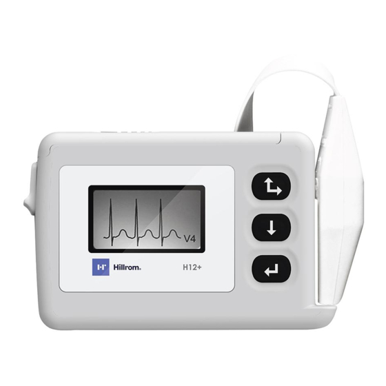
INTRODUCTION SECTION 1 Manual Purpose This manual explains how to operate the 24-hour and 48-hour 12-lead H12+™ digital Holter recorder. It shows the user how to: Prepare the patient Use the recorder Configure the recorder Troubleshoot Audience This manual is written for clinical professionals who are expected to have a working knowledge of medical procedures and terminology as required for monitoring cardiac patients. -
Page 19: Patient Preparation Section
SECTION 1 The 48-hour H12+ recorder uses a single AA lithium battery to provide continuous 12-lead data recorded over a 48-hour period and a removable 48-hour CF card for data storage. A removable 24-hour CF card with an AA alkaline battery can also be used with the 48-hour recorder for 24-hour recordings. -
Page 20: Recorder Setup
SECTION 1 Recorder Setup Opening and Closing the Battery Door The CF card slot and the battery compartment are accessible via the battery door of the H12+ recorder. To open the battery door, hold the latch (1) down and then depress and slide the battery door (2) until it stops. Lift and remove the battery door. -
Page 21: Using The Keypad
SECTION 1 Using the Keypad The keypad is located on the front, right side of the H12+ recorder. Three keys are available for navigating through the LCD screens and for entering the patient ID and event markers during the recording: Up/Right, Down, and Enter. -
Page 22: Leadform Patient Cable
SECTION 1 LeadForm Patient Cable The LeadForm patient cable consists of a connector block, main cable, and ten lead wires connected to the main cable. Each lead wire terminates in a snap connector. The lead wires are positioned on the main cable to follow the contour of the torso. -
Page 23: H12+ Recorder In Carrying Case
SECTION 1 H12+ Recorder in Carrying Case... -
Page 24: Part Numbers
SECTION 1 Part Numbers Description Part Numbers H12+ 24-Hour Recorder H12PLUS-AXX-XXXXX H12+ 24-Hour CF Card 11018-001-50 H12+ 48-Hour Recorder H12PLUS-BXX-XXXXX H12+ 48-Hour CF Card 11018-001-52 H12+ 24-Hour Recorder with High-Fidelity CF Card H12PLUS-CXX-XXXXX (24 Hour) H12+ 48-Hour Recorder with High-Fidelity Extend CF H12PLUS-HXX-XXXXX Card (30 Hour) H12+ High-Fidelity CF Card (24 Hour) -
Page 25: Specifications
SECTION 1 Specifications Feature Specifications Instrument Type 12-lead digital Holter recorder Input Channels Simultaneous acquisition of all leads Standard Leads Acquired I, II, III, aVR, aVL, aVF, V1, V2, V3, V4, V5, and V6 Input Impedance Input Dynamic Range Meets or exceeds the requirements of ANSI/AAMI EC38 Electrode Offset Tolerance Frequency Response 10,000 s/sec/channel used for pacemaker spike detection... -
Page 26: Patient Hookup
PATIENT PREPARATION SECTION 2 Patient Hookup Skin Preparation Good skin preparation prior to electrode attachment is very important to ensure good signal quality when recording patient data. Poor electrode-to-skin contact may cause artifact (noise) to be included in the recording which can affect the analysis of the ECG data. - Page 27 SECTION 2 Limb Electrode Precordial Electrode AAMI Placement AAMI Placement On or below the right clavicle as Fourth intercostal space at the shown right sternal border On or below the left clavicle as Fourth intercostal space at the shown left sternal border Reference or ground lead, should be placed in a stable Midway between V2 and V4...
-
Page 28: Inserting And Removing Cf Cards
USING THE RECORDER SECTION 3 Inserting and Removing CF Cards To insert a CF card, open the battery door of the recorder. Position the card above the empty card slot with the arrow on the card pointing down. Place the CF card in the slot and gently push down until the eject button (to the right of the card slot) pops up to the full upright position. -
Page 29: Main Menu Options
SECTION 3 Main Menu Options The main menu includes the following options: LEAD CHECK DISPLAY ECG ENTER ID RECORD (see Section 3, Using the Recorder) CONFIGURE The following operational flowchart of main menu options depicts the flow of functionality using Up/Right, Down, and Enter. -
Page 30: Starting A Recording Session
SECTION 3 Starting a Recording Session Insert a formatted CF card and a new AA battery. (If necessary, reformat the CF card using the proper utility with H-Scribe system software.) Hookup the patient (see Section 2, Patient Preparation). Verify the quality of the hookup by checking the impedances. Scroll through the main menu until LEAD CHECK is displayed, press Enter. -
Page 31: Displaying Ecg Leads
SECTION 3 Verify the amplitude and signal quality by displaying each of the leads. Scroll through the main menu until DISPLAY ECG is displayed, press Enter. Displaying ECG Leads DISPLAY ECG is used to visually inspect leads I, II, III, V1, V2, V3, V4, V5, and V6 before starting a recording. - Page 32 SECTION 3 To enter the patient ID, the cursor is moved to the desired letter or digit in the alphanumeric table and then selected by pressing Enter. The cursor is initially located in the upper-left corner of the screen over the number ‘0’. To move the cursor one letter or digit to the right on a line, press Up/Right.
- Page 33 SECTION 3 To begin recording, scroll through the main menu until RECORD is displayed, press Enter. An initializing message will be displayed for up to 3 seconds; “Recording” and the current time appear when the recording actually begins. During normal operation of the 24-hour H12+ recorder, the current time (HH:MM:SS) is displayed in the middle of the screen for the entire recording session.
-
Page 34: Entering (Optional) Diary Events
SECTION 3 During normal operation of the 24-hour H12+ recorder using a high-fidelity CF card, the current time (HH:MM:SS) is displayed in the middle of the screen for the entire recording session. “HF” is displayed above the current time to indicate that a high- fidelity CF card is being used. -
Page 35: Ending A Recording Session
SECTION 3 Ending a Recording Session At the end of the 24-hour or 48-hour recording session, the time is automatically cleared from the LCD screen and a “Recording Complete” message is displayed. To proceed: Remove the battery door of the H12+ recorder. -
Page 36: Configuring Date/Time And Language
CONFIGURING THE RECORDER SECTION 4 Configuring Date/Time and Language CONFIGURE is used to set the current date and time, the date format and language defaults, and to display the software version number. These settings typically are set before the initial patient recording and do not need to be set on a per patient basis. - Page 37 SECTION 4...
- Page 38 SECTION 4 Setting Date and Time DATE/TIME is used to set the current date and time and to set an alternative format for the displayed date. From the configuration menu, scroll to DATE/TIME, press Enter. The DATE/TIME menu includes the following options: ...
-
Page 39: Viewing Software Version Number
SECTION 4 Viewing Software Version Number VERSION displays the current software version installed on the H12+ recorder. “48 Hour” will be displayed when the model is a 48-hour H12+ recorder. From the CONFIGURE menu, scroll to VERSION using Up/Right or Down; press Enter to view software version. -
Page 40: Cleaning The H12+ Recorder And Accessories
MAINTENANCE SECTION 5 Cleaning the H12+ Recorder and Accessories Remove cables and disconnect power source from device before cleaning. Wash the carry case by hand with fabric detergent and then air dry. Do not machine dry the case. For general cleaning, use a soft, lint-free cloth lightly moistened with a mild soap and water solution. Wipe and air dry. -
Page 41: Disposal Of Waste Materials
SECTION 5 Disposal of Waste Materials The H12+ uses one AA battery and disposable monitoring electrodes. Disposal must be in accordance with the following procedures: Battery: applicable disposal or recycling standards Electrodes: normal waste... -
Page 42: Troubleshooting
Replace existing battery with a fully charged battery. ‘LOW BATTERY A’ ‘CARD ERROR’ CF card error. Contact Mortara Technical Support Group. Please make note of the ‘CARD ERROR A – E’ letter or number following the CARD ERROR message when present. -
Page 43: Translations
TRANSLATIONS APPENDIX B Table of Translations Italian Spanish Dutch English German DEUTSCH ITALIANO ESPAÑOL HOLLAND INITIALIZING INIZIALIZ. INICIANDO INITIALISIERUNG INITIALIZING RECORD INIZIO GRABAR AUFNAHME OPNAME LEAD CHECK DERIVAZIONI TEST ELECT ABL.TEST LEAD DISPLAY ECG MOSTRA ECG MOSTRAR ECG EKG-ANZEIGE TOONT ECG ENTER ID ID PAZIENTE INTRO ID... - Page 44 TRANSLATIONS APPENDIX B Table of Translations (continued) Polish Finnish Portuguese English French FRANÇAIS POLSKI SUOMI PORTUGUES INITIALIZING INITIALISEZ INICJALIZACJA ALUSTAA INICIALIZACAO RECORD ENREGISTRER START TALLENNUS REGISTO LEAD CHECK DÉRIVATIONS ELEKTRODY ELEKTRODIT DERIVAÇÕES DISPLAY ECG AFFICH. ECG NÄYTÄ EKG MOSTRAR ECG ENTER ID ID PATIENT OPIS...
Need help?
Do you have a question about the H12+ and is the answer not in the manual?
Questions and answers