
Subscribe to Our Youtube Channel
Related Manuals for Woodward 721


Summary of Contents for Woodward 721
- Page 1 Product Manual 02714 (Revision A) Original Instructions 721 Digital Control 8280-133, 8280-134, 9906-118, 9906-119 Hardware Only Hardware Manual...
- Page 2 Protection of Electronic Controls, Printed Circuit Boards, and Modules. Woodward reserves the right to update any portion of this publication at any time. Information provided by Woodward is believed to be correct and reliable. However, no responsibility is assumed by Woodward unless otherwise expressly undertaken.
-
Page 3: Table Of Contents
721 C ..............21 ONTROL PECIFICATIONS Illustrations and Tables Figure 1-1. 721 Digital Speed Control ..............3 Figure 1-2. Hand Held Programmer ............... 4 Figure 3-1. 721 Control Internal Jumpers ............... 7 Figure 3-2. 721 I/O ....................11 ... -
Page 4: Electrostatic Discharge Awareness
PCB from the control cabinet, place it in the antistatic protective bag. To prevent damage to electronic components caused by improper handling, read and observe the precautions in Woodward manual 82715, Guide for Handling and Protection of Electronic Controls, Printed Circuit Boards, and Modules. -
Page 5: Chapter 1. General Information
The control can be used in load sharing systems as it contains circuitry and connections to deal with this. The 721 control (Figure 1-1) consists of a single printed circuit board in a sheet- metal chassis. Connections are via three terminal strips and a 9-pin subminiature D connector. -
Page 6: 721 Digital Speed Control Accessories
721 Digital Speed Control Accessories Hand Held Programmer (Figure 1-2), part number 9905-292, is used for adjusting the 721 control. It plugs into the serial port of the control. SPM-A Synchronizer, for synchronizing the generator phase to that of the power bus. -
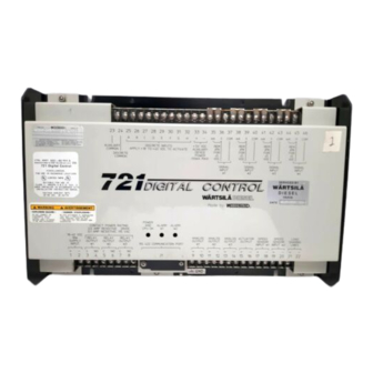
Page 7: Figure 1-1. 721 Digital Speed Control
Manual 02714 721 Digital Control Hardware Manual Figure 1-1. 721 Digital Speed Control Woodward... - Page 8 721 Digital Control Hardware Manual Manual 02714 Figure 1-2. Hand Held Programmer Woodward...
-
Page 9: Chapter 2. Installation
Power Requirements The high-voltage versions of the 721 Digital Speed Control require a voltage source of 88 to 132 Vac 45 to 65 Hz or 90 to 150 Vdc. The low-voltage versions require a voltage source of 18 to 32 Vdc. -
Page 10: Internal Jumpers
Manual 02714 Internal Jumpers The 721 control has nine, two-position internal jumpers (JPR1 through JPR18) located on the top of the printed circuit board. If it is necessary to change any jumper to match your control requirements, and this suits the nature of the software, be sure to read page ii, Electrostatic Discharge Awareness. -
Page 11: Figure 3-1. 721 Control Internal Jumpers
Manual 02714 721 Digital Control Hardware Manual Figure 3-1. 721 Control Internal Jumpers Woodward... - Page 12 Power supply output must be low impedance (for example, directly from batteries). DO NOT power the control from high-voltage sources with resistors and zener diodes in series with the control power input. The 721 control contains a switching power supply which requires a current surge to start properly.
- Page 13 Discrete Inputs (Terminals 25–32) Discrete inputs are the switch input commands to the 721 control. In low voltage systems, or other systems where nominal 24 Vdc is available, the discrete inputs should be powered by this external voltage.
-
Page 14: Installation Checkout Procedure
(except the power supply input and the discrete inputs). If any other analog input or output is used in a common ground system, an isolator must be installed. A number of manufacturers offer 20 mA loop isolators. Consult Woodward for further information. -
Page 15: Figure 3-2. 721 I/O
Manual 02714 721 Digital Control Hardware Manual Check for grounds Check for grounds by measuring the resistance from all control terminals to chassis. All terminals except terminals 2 and 24 should measure infinite resistance (the resistance of terminals 2 and 24 depends on whether a floating or grounded power source is used). -
Page 16: Chapter 3. Entering Control Set Points
BKSP and SPACE keys will scroll through the display to show the remainder of a prompt if it is longer than the display screen's 18 characters. The 721 has two sets of menus; the Service menus and the Configure menus. The Service menus allow easy access and tuning while the engine is running. - Page 17 Manual 02714 721 Digital Control Hardware Manual To leave the Configure menus press the ESC key. The set points will be automatically saved when leaving Configure. Service Menus To access the Service menus press the key. To move between menus, and to move through set points within menus follow the instructions as for the Configure menus.
-
Page 18: Figure 4-1. Hand Held Programmer Functions
+ (plus) Decreases set point values by one step at a time. (solid square) Not used. Displays the 721 control part number and software revision level. To return to menu header or to main screen. SAVE Saves entered values (set points). -
Page 19: Chapter 4. Function Block Diagram
It uses special symbols, some of which are unique to Woodward; each symbol is identified and described in the first sheet of the function block diagram. The function block diagram is drawn as a design aid to act as an interface between the Woodward application engineer and the customer in defining the control function. - Page 20 721 Digital Control Hardware Manual Manual 02714 Example: The speed inputs are shown to the left of the left dashed line, which represents the hardware inputs. To the right of the right dashed line is an output to the hardware, which in turn, is an output to the customer.
-
Page 21: Chapter 5. Product Support And Service Options
A current list of Woodward Business Partners is available at www.woodward.com/directory. Product Service Options Depending on the type of product, the following options for servicing Woodward products may be available through your local Full-Service Distributor or the OEM or Packager of the equipment system. -
Page 22: Returning Equipment For Repair
To prevent damage to electronic components caused by improper handling, read and observe the precautions in Woodward manual 82715, Guide for Handling and Protection of Electronic Controls, Printed Circuit Boards, and Modules. -
Page 23: Engineering Services
Field Service engineering on-site support is available, depending on the product and location, from one of our Full-Service Distributors. The field engineers are experienced both on Woodward products as well as on much of the non- Woodward equipment with which our products interface. -
Page 24: Technical Assistance
Manual 02714 Technical Assistance If you need to contact technical assistance, you will need to provide the following information. Please write it down here before contacting the Engine OEM, the Packager, a Woodward Business Partner, or the Woodward factory: General... -
Page 25: 721 Control Specifications
8280-133 721 hardware platform/ low-voltage power supply 8280-134 721 hardware platform/ high-voltage power supply 9906-118 721 hardware platform, marine type approval/ low-voltage power supply 9906-119 721 hardware platform, marine type approval/ high-voltage power supply 9905-292 Hand Held Programmer Power Supply Rating 18–32 Vdc (24 Vdc nominal) - Page 26 Email and Website—www.woodward.com Woodward has company-owned plants, subsidiaries, and branches, as well as authorized distributors and other authorized service and sales facilities throughout the world. Complete address / phone / fax / email information for all locations is available on our website.
Need help?
Do you have a question about the 721 and is the answer not in the manual?
Questions and answers