Table of Contents
Advertisement
Quick Links
WOODWARD GOVERNOR (JAPAN). LTD.,
251-1 Nakazawa, Tomisato-city
Chiba - ken, 286 - 0222, Japan
Phone: 81(476)93-4661 Fax: 81(476)93-7939
Operation and Calibration Manual
23 24 25 26 27 28 29 30 31 32 33 34 35 36 37 38 39 40 41 42 43 44 45 46
W
W
D
D
OODW AR
OODW AR
A
B
C
D
E
AUXILIARY
DISCRETE INPUTS
COMMON
APPLY +18 TO +40 VDC TO ACTIVATE
DISCRETE
COMM ON
721
CONTACT POWER RATING
2.0 AMP RESISTIVE 28VDC
0.1 AMP RESISTIVE 115VAC
POWER
AND
CPU OK
18-40VDC
RELAY
RELAY
RELAY
18W
OUTPUT
OUTPUT
OUTPUT
SUPPLY
#1
#1
#1
INPUT
+
-
C
NO
C
NO
C
NO
1
2 3 4
5 6 7 8
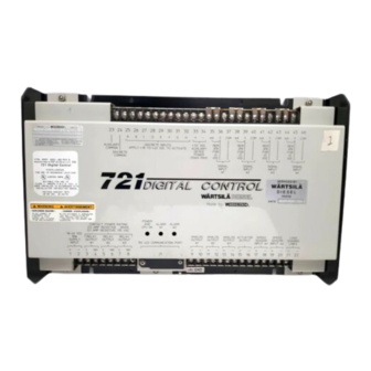
721 Digital Speed Control
For Marine Propulsion Application
F
G
H
+
-
mA
+
mA
+
mA
+
COM
COM
COM
-
-
-
REM
REM
REM
+5 VDC
JPR
JPR
JPR
AUXILIARY
FOR
FOR
FOR
DEVICE
+ - 5
+ - 5
+ - 5
POWER
(50mA MAX)
VDC
VDC
VDC
SIGNAL
SIGNAL
SIGNAL
INPUT
INPUT
INPUT
#1
#2
#3
DIGITAL CONTROL
W
D
W
OODWAR
D
OODWAR
WARNING
___
ALARM
ALARM
#1
#2
ANALOG
ANALOG
ANALOG
ACTUATOR
SPEED
SPEED
OUTPUT
OUTPUT
OUTPUT
OUTPUT
SENSOR
SENSOR
#1
#2
#3
INPUT#1
INPUT#2
+
-
+
-
+
-
+
-
+
-
+
9
10
11
12 13
14
15 16 17 18 19 20 21 22
D/N 9907-717
Manual 26004
mA
+
COM
-
REM
JPR
FOR
+ - 5
VDC
SIGNAL
INPUT
#4
LOAD
SHARING
LINES
-
+
-
Advertisement
Chapters
Table of Contents

Subscribe to Our Youtube Channel
Related Manuals for Woodward 721


Summary of Contents for Woodward 721
- Page 1 INPUT 2 3 4 5 6 7 8 12 13 15 16 17 18 19 20 21 22 721 Digital Speed Control For Marine Propulsion Application D/N 9907-717 WOODWARD GOVERNOR (JAPAN). LTD., 251-1 Nakazawa, Tomisato-city Chiba - ken, 286 - 0222, Japan...
- Page 2 Revisions—Text changes are indicated by a black line alongside the text. Woodward Governor Company reserves the right to update any porti o n of thi s publ i c ati o n at any ti m e. Informati o n provided by Woodward Governor Company is bel i e ved to be correct and rel i a ble.
-
Page 3: Table Of Contents
Japanese version with a later revision. CONTENTS Page Chapter 1. General Information Introduction ······································································································································································ 1 Application ······································································································································································· 1 721 Control Accessories ·············································································································································· 1 Chapter 2. Electrostatic Discharge Awareness Summary ········································································································································································ 3 General Information ······················································································································································ 3 Chapter 3. Installation Scope ··············································································································································································· 5 Unpacking ·······································································································································································... - Page 4 Fig 4. Control Gain as a Function of Control Output ········································································································ 32 Fig 5. Speed Filter ····································································································································································· 33 Fig 6. T orque Fuel Limit Curve ·············································································································································· 33 Set Point Record Sheets ······························································································································· Function Block Diagram ·············································································································· Appendix P1 Control Wiring Diagram ··············································································································· Appendix P4 Woodward...
-
Page 5: Chapter 1. General Information
Hardware manual). Application This 721 Digital Speed Control was designed as a marine propulsion engine control to use with a changeable pitch propeller control. This control has two sets of control dynamics which the operator can switch to get most suitable engine operation: either when only the propeller shaft is driven, or when both the propeller shaft and the generator are driven. - Page 6 721DSC for Marine Propulsion Application Manual 26004 Woodward...
-
Page 7: Summary
• When replacing a PCB, keep the new PCB in the plastic antistatic protective bag it comes in until you are ready to install it. Immediately after removing the old PCB from the control cabinet, place it in the antistatic protective bag. Woodward... - Page 8 721DSC for Marine Propulsion Application Manual 26004 Woodward...
-
Page 9: Chapter 3. Installation
Chapter 3 Installation Scope This chapter contains general installation instructions for the 721 control. Power requirements, environmental precautions, and location considerations are included to help you determine the best location for the control. Additional information includes unpacking instructions and electrical connections. -
Page 10: Electrical Connection
Governing Systems , for more information. Power Requirement The 721 control requires the following power supply input voltages, with 18 watts as the nominal power consumption at rated voltage: • 18-40 Vdc (24 Vdc or 32 Vdc nominal) Discrete input voltages provide on/off command signals (like RUN/STOP or IDLE/START) to the electronic control. - Page 11 CAUTION To prevent damage to the engine, apply power to the 721 control at least 15 seconds prior to starting the engine. The control must have time to complete its power up diagnostics and become operational. Do not start...
- Page 12 721DSC for Marine Propulsion Application Manual 26004 Woodward...
-
Page 13: Chapter 4. Description Of Operation
Description of Operation General This section provides an overview of the features and operation of the 721 Digital Speed Control. In the last part of this manual, the control block diagram and the plant wiring diagram are shown for reference in the following descriptions. -
Page 14: Speed Reference
9951-626, GCB 2 must be opened, and vice versa.) Connect the tie circuit breaker (TCB in drawing 9951-626). When one of the 721 controls detects that the GCB x AUX contact (contact E) is open and the TCB contact (contact F) is closed, this control will switch the operation mode from isochronous mode to KW droop mode to perform load transfer. -
Page 15: Fuel Limit
Three 4-20mA outputs are provided for monitoring Engine rpm, Speed Reference, and Rack Position (Actuator output), which are configurable at 4 mA and 20 mA. Three relay outputs are provided for Major Alarm indication, Minor Alarm indication, and Load Transferring indication. Woodward... - Page 16 721DSC for Marine Propulsion Application Manual 26004 Woodward...
-
Page 17: Chapter 5. Entering Control Set Points
Because of the variety of installations, plus system and component tolerances, set points input to two 721 controls could not be identical even if these 721 controls are installed in same engine control systems. Therefore, the 721 control must be tuned to each system for optimum performance. -
Page 18: Configure Menus
721DSC for Marine Propulsion Application Manual 26004 The 721 has two sets of menus; the Service menus and the Configure menus. The Service menus allow easy access and tuning while the engine is running. The Configure menus may only be entered if the I/O is shut down, and hence the engine stopped. -
Page 19: Service Menus
To access the Service menus, press the key at the master screen (“WOODWARD GOVERNOR, 721 DIGITAL CONTROL”). To move between menus, and to move through set points within menus, follow the instructions as for the Configure menus. Also to return to the menu header, or to leave Service, follow the Configure instructions. -
Page 20: Hand Held Programmer Keys
+ (plus) Decreases set point values by one step at a time. (solid square) Not used. Displays the 721 control part number and software revision level. To return to menu header or to main screen. SAVE Saves entered values (set points). - Page 21 Manual 26004 721DSC for Marine Propulsion Application Figure-1. Hand Held Programmer Functions Woodward...
-
Page 22: Set Points List
8. Gain Slope 10.0 9. Speed Filter 20.0 15.0 Dynamics 2 1. Idle Prop. Gain2 0.001 50.0 2. Rated Prop. Gain2 0.001 50.0 3. Integrator Rate 2 50.0 4. Derivative Ratio2 100.0 5. Window Width2 50.0 10.0 6. Gain Ratio2 10.0 Woodward... - Page 23 4. Torque Lmt P2,rpm 5. Torque Lmt P2,% 10.0 100.0 57.0 6. Torque Lmt P3,rpm 7. Torque Lmt P3,% 10.0 100.0 83.0 8. Torque Lmt P4,rpm 9. Torque Lmt P4,% 10.0 100.0 87.0 10. Maximum Fuel Limit 50.0 100.0 87.0 Woodward...
-
Page 24: Name Min Value Max Value
To prevent possible damage to the engine resulting from improper control settings, make sure you save the set points before removing power from the control. Failure to save the set points before removing power from the control causes them to revert to the previously saved settings. Woodward... -
Page 25: Configure Menus
This set point determines to which direction the actuator rotates when the actuator output current from the 721 control increases. Setting “FALSE” will select Forward acting output. In this case the actuator output current must be increased to increase fuel. - Page 26 CAUTION Never set Max Hz to a value over 125% of the frequency at Raise Limit. Otherwise the 721 control may not control the engine. Normal Opn Minr Alm Ry This set point determines the operating mode of Minor Alarm relay. Set the set point to “TRUE”...
-
Page 27: Service Menus
Tune the control dynamics for stable engine operation and most suitable transient performance. This 721 control has two sets of dynamics. The dynamics used in the 721 control are selected with an external contact input. See figure 2 for tuning Prop.Gain (traditional Gain in Woodward controls) and Integrator Rate (traditional Reset in Woodward controls). - Page 28 This is the roll-off frequency for the firing torsional filter. The formula to get the proper roll-off frequency setting is: camshaft frequency = (engine rpm)/60 [for 2-cycle engines] = (engine rpm)/120 [for 4-cycle engines] firing frequency (camshaft frequenc y) × (number of cylinders) Initially set the filter frequency to the firing frequency. Woodward...
-
Page 29: Dynamics 2
This allows a lower gain at steady state for better stability and reduced steady-state actuator linkage movement. Speed Settings Set set points for speed references. Start Speed Start Speed is the speed reference selected when the Start Pos/Idle contact (external contact B) is open. Woodward... -
Page 30: Idle Speed
Set this set point to the engine speed in RPM when the tachometer output channel outputs 4 mA. 12. Tach at 20mA Output Set this set point to the engine speed in RPM when the tachometer output channel outputs 20 mA. Woodward... -
Page 31: Kw Settings
Torque Lmt P2, % Torque Lmt P2, % is the maximum actuator output current in percent at the second torque limit. Torque Lmt P3, rpm Torque Lmt P3, rpm is the engine speed in RPM at the third torque limit. Woodward... -
Page 32: Display 2
Contact C Status displays the status of the RAISE SPEED contact (open or closed). Contact D Status Contact D Status displays the status of the LOWER SPEED contact (open or closed). Contact E Status Contact E Status displays the status of the Generator Circuit Breaker Aux. (GCB AUX) contact (open or closed). Woodward... -
Page 33: Alarms
No.2 MPU Failure displays “TRUE” if MPU #2 has failed. KW Signal Fail KW Signal Fail displays “TRUE” if the 4-20 mA KW transducer signal has failed. Spd Set Signal Fail Spd Set Signal Fail displays “TRUE” if the 4-20 mA remote speed setting signal has failed. Woodward... - Page 34 To prevent possible damage to the engine resulting from improper control settings, make sure you save the set points before removing power from the control. Failure to save the set points before removing power from the control causes them to revert to the previously saved settings. Woodward...
-
Page 35: Fig 2. Typical Transient Response Curve
Manual 26004 721DSC for Marine Propulsion Application Figure 2. Typical Transient Response Curve Woodward... -
Page 36: Fig 3. Control Gain As A Function Of Speed Error
Figure 3. Control Gain as a Function of Speed Error CONTROL GAIN GAIN SLOPE GAIN ADJUSTMENT GAIN SLOPE ADJUSTMENT GAIN GAIN BREAKPOINT ADJUSTMENT GAIN BREAKPOINT 100% CONTROL OUTPUT CURRENT Figure 4. Control Gain as a Function of Control Output Woodward... -
Page 37: Fig 5. Speed Filter
Figure 5. Speed Filter Actuator output (%) Torque Lmt P4,% Torque Lmt P4,rpm Max Lmt,% Torque Lmt P3,% Torque Lmt P3,rpm Torque Lmt P2,% Torque Lmt P2,rpm Torque Lmt P1,% Torque Lmt P1,rpm Engine Speed (RPM) Figure 6. Torque Fuel Limit Curve Woodward... - Page 38 721DSC for Marine Propulsion Application Manual 26004 Woodward...
-
Page 39: Chapter 7. Major Alarm And Minor Alarm
721 control to activate a major alarm. Minor Alarm If the 721 control detects a minor alarm, it will activate the minor alarm relay, but it does not shut down the engine. The conditions to cause a minor alarm are: ∗... - Page 40 721DSC for Marine Propulsion Application Manual 26004 Woodward...
-
Page 41: Set Point Record Sheets
Manual 26004 721DSC for Marine Propulsion Application WOODWARD GOVERNOR COMPANY ENGINE CONTROLS DIVISION 721 DIGITAL ENGINE CONTROL FOR KAWASAKI HEAVY INDUSTRIES, LTD. SYSTEM 9907-717 ====================================================================== C.C1 ∗ CONFIGURE MENU ∗ Reverse Acting Act #FALSE (TRUE, FALSE) _________ No.1 Gear Teeth... -
Page 42: Kw Droop Set(%)
_________ ∗600.0 (0.0, 1000.0) 14 Spd Set at 20mA Output _________ ====================================================================== S.S5 ∗ Kw Setting ∗ ∗1280.0 (100.0, 10000.0) Rated KW _________ ∗1500.0 (100.0, 10000.0) 20mA KW Load Input _________ ∗ 5.0 (0.0, 10.0) Kw Droop Set(%) _________ Woodward... -
Page 43: Fuel Limit
_________ 11 Contact G Status _________ 12 Contact H Status _________ 13 Major Alarm Ry Status _________ 14 Minor Alarm Ry Status _________ 15 Transfer Mode Ry Status _________ 16 #1 LED Status _________ 17 #2 LED Status _________ Woodward... - Page 44 721DSC for Marine Propulsion Application Manual 26004 ====================================================================== S.S8 ∗ Alarms ∗ Minor Alarm _________ Major Alarm _________ No1 MPU Failure _________ No2 MPU Failure _________ KW Signal Fail _________ Spd Set Signal Fail _________ ∗ FALSE (TRUE, FALSE) Fault Reset _________ Woodward...
-
Page 45: Appendix P1
Appendix-P1... - Page 46 Appendix-P2...
- Page 47 Appendix-P3...
- Page 48 Appendix-P4...
- Page 49 Appendix-P5...
- Page 50 Appendix-P6...
- Page 51 721 Control Specifications Woodward Part Numbers: 8237-735 Power Supply Rating 18–32 Vdc (24 Vdc or 32Vdc nominal) Power Consumption 18 watts nominal Steady State Speed Band magnetic pickup: 400–15 000 Hz (8–2100 rpm) proximity switch: 7.5–1000 Hz (8–2100 rpm) Discrete Inputs (8)
- Page 52 Phone +1 (970) 482-5811 • Fax +1 (970) 498-3058 Email and Website—www.woodward.com Woodward has company-owned plants, subsidiaries, and branches, as well as authorized distributors and other authorized service and sales facilities throughout the world. Complete address / phone / fax / email information for all locations is available on our website.
Need help?
Do you have a question about the 721 and is the answer not in the manual?
Questions and answers