
Subscribe to Our Youtube Channel
Related Manuals for Woodward GCP-20 Series


Summary of Contents for Woodward GCP-20 Series
- Page 1 37128A GCP-20 Series Genset Control Operation Manual Software Version 1.0xxx Manual 37128A...
- Page 2 Provides other helpful information that does not fall under the warning or caution categories. Woodward Governor Company reserves the right to update any portion of this publication at any time. Information provided by Wood- ward Governor Company is believed to be correct and reliable. However, Woodward Governor Company assumes no responsibility unless otherwise expressly undertaken.
-
Page 3: Table Of Contents
Manual 37128A GCP-20 Series - Genset Control Revision History Rev. Date Editor Change NEW 03-05-22 Release 05-08-02 Re-release in new format with general update Content 1. G ..................9 HAPTER ENERAL NFORMATION Related Documents..........................9 Overview ...............................10 2. GCP-20 S .................12 HAPTER... - Page 4 Manual 37128A GCP-20 Series - Genset Control 7. F .................. 32 HAPTER UNCTIONAL ESCRIPTION Considerations for …..........................32 … Different Options........................32 … Equipment with One Power Circuit Breaker ................32 … Equipment with Induction Generators ................... 32 Set Point Table ............................. 33 Control Inputs ............................
- Page 5 Manual 37128A GCP-20 Series - Genset Control 9. C ....................68 HAPTER ONFIGURATION Basic Data.............................68 Version Number (Software Version)...................68 Service Display .............................69 Status of Power Circuit Breakers and Relays ................70 Basic Configuration ..........................71 Configuration Access........................71 Basic Settings Configuration.......................71 Direct Configuration ........................72 Measuring .............................73...
- Page 6 Manual 37128A GCP-20 Series - Genset Control Discrete Inputs............................ 121 Alarm Inputs ..........................121 Configuring the Text for the Discrete Inputs ................123 Control Inputs ........................... 124 Terminal 6..........................126 Analog Inputs (Option T4) ........................127 Setting the Analog Inputs ......................127 Output Configuration ..........................
- Page 7 Manual 37128A GCP-20 Series - Genset Control Illustrations and Tables Illustrations Figure 2-1: Overview................................12 Figure 4-1: Housing - Dimensions ............................15 Figure 4-2: Housing - Control panel cut-out ..........................16 Figure 4-3: Side view - without clamps ........................... 16 Figure 4-4: Side view - with clamps ............................
- Page 8 Manual 37128A GCP-20 Series - Genset Control Tables Table 1-1: Manual - overview..............................9 Table 2-1: Functional overview ............................... 13 Table 4-1: Housing - panel cut-out ............................16 Table 6-1: Power supply - terminal assignment........................21 Table 6-2: Voltage measuring: generator - terminal assignment ..................... 22 Table 6-3: Voltage measuring: busbar / remanence - terminal assignment................
-
Page 9: Chapter 1. General Information
Manual 37128A GCP-20 Series - Genset Control Chapter 1. General Information Related Documents ≡≡≡≡≡≡≡≡≡≡≡≡≡≡≡≡≡≡≡≡≡≡≡≡≡ Type English German GCP-20 Series GCP-20 – Manual this manual 37128 Additional Manuals LeoPC1 – User Manual 37146 GR37146 PC program for configuration, parameter visualization, remote control, data logging, language upload, alarm and user management, and event recorder management. -
Page 10: Overview
Manual 37128A GCP-20 Series - Genset Control Overview ≡≡≡≡≡≡≡≡≡≡≡≡≡≡≡≡≡≡≡≡≡≡≡≡≡ The GCP-20 series generator set controllers provide the following functions: Gen-set control • Engine and generator protection • Engine data measurement - ○ including oil pressure and oil temperature, coolant temperature, battery voltage, speed, service hours, etc. - Page 11 Manual 37128A GCP-20 Series - Genset Control Examples: • GCP-2245B/LSX (GCP-22 with 400 Vac and ../5 A measuring inputs, Package LSX [2 breaker logic; analog controller n/f, V, P, Q; real power set point 0/4 to 20mA; 3 analog inputs, 2 analog outputs]) •...
-
Page 12: Chapter 2. Gcp-20 Series Overview
Manual 37128A GCP-20 Series - Genset Control Chapter 2. GCP-20 Series Overview on/off on/off on/off on/off on/off ϑ ϑ ϑ /n/Vbatt/.. /n/Vbatt/.. /n/Vbatt/.. Start/Stop Start/Stop Start/Stop n/f/P n/f/P GCP-20 GCP-21 GCP-22 Figure 2-1: Overview Page 12/190 © Woodward... -
Page 13: Functional Overview
2) only two analog inputs Table 2-1: Functional overview The GCP-20 series consists of three models which are intended for different applications and requirements. This manual covers all available versions of the GCP-20. Please take information about the differences between the units from this section. -
Page 14: Chapter 3. Electrostatic Discharge Awareness
CAUTION To prevent damage to electronic components caused by improper handling, read and observe the pre- cautions in Woodward manual 82715, Guide for Handling and Protection of Electronic Controls, Printed Circuit Boards, and Modules. Page 14/190 © Woodward... -
Page 15: Chapter 4. Housing
Manual 37128A GCP-20 Series - Genset Control Chapter 4. Housing Dimensions ≡≡≡≡≡≡≡≡≡≡≡≡≡≡≡≡≡≡≡≡≡≡≡≡≡ Type APRANORM DIN 43 700 Housing 144 × 96 × 118 mm Dimensions 138 [+1.0] × 92 [+0.8] mm Front cut out Screw type connector, depending on plug connector 1.5 mm² or 2.5 mm²... -
Page 16: Panel Cut-Out
Manual 37128A GCP-20 Series - Genset Control Panel Cut-Out ≡≡≡≡≡≡≡≡≡≡≡≡≡≡≡≡≡≡≡≡≡≡≡≡≡ h' h H Figure 4-2: Housing - Control panel cut-out Measure Description Tolerance Height Total 96 mm Panel cut-out 92 mm + 0.8 mm Housing dimension 88 mm Width Total... -
Page 17: Installation
Manual 37128A GCP-20 Series - Genset Control Installation ≡≡≡≡≡≡≡≡≡≡≡≡≡≡≡≡≡≡≡≡≡≡≡≡≡ For installation into a door panel proceed as follows: Panel cut-out Cut out the panel according to the dimensions in Figure 4-1. Insert control into cut-out Move housing into panel Insert the control into the panel cut-out. Verify that the control fits cor- rectly in the cut-out. -
Page 18: Chapter 5. Wiring Diagrams
Manual 37128A GCP-20 Series - Genset Control Chapter 5. Wiring Diagrams Analog input 4 [T4] 0/4 to 20 mA Analog input 3 [T3] 0/4 to 20 mA Analog input 2 [T2] VDO, 0 to 380 Ohm (40 to 120 °C) The PC configuration plug is located on the side of the unit. -
Page 19: Figure 5-2: Wiring Diagram - Gcp-21
Manual 37128A GCP-20 Series - Genset Control Analog input 4 [T4] 0/4 to 20 mA Analog input 3 [T3] Externe Sollwertvorgabe 0/4 to 20 mA Analog output 0/4 to 20 mA Analog input 2 [T2] VDO, 0 to 380 Ohm (40 to 120 °C) The PC configuration plug is located on the side of the unit. -
Page 20: Figure 5-3: Wiring Diagram - Gcp-22
Manual 37128A GCP-20 Series - Genset Control Analog input 4 [T4] 0/4 to 20 mA Analog input 3 [T3] External setpoint value 0/4 to 20 mA Analog output 0/4 to 20 mA Analog input 2 [T2] VDO, 0 to 380 Ohm (40 to 120 °C) The PC configuration plug is located on the side of the unit. -
Page 21: Chapter 6. Connections
Manual 37128A GCP-20 Series - Genset Control Chapter 6. Connections Power Supply ≡≡≡≡≡≡≡≡≡≡≡≡≡≡≡≡≡≡≡≡≡≡≡≡≡ 8 to 36 Vdc D1 = P600M C1 = 47,000 uF / 40 V for 12 V DC systems Power supply 8 to 36 Vdc 8 to 36 V DC (in normal operation) (min. -
Page 22: Measuring Inputs
Manual 37128A GCP-20 Series - Genset Control Measuring Inputs ≡≡≡≡≡≡≡≡≡≡≡≡≡≡≡≡≡≡≡≡≡≡≡≡≡ NOTE The following is valid for units with a software version older than V1.0700: The three-phase system must have a clockwise rotary field (right-handed rotary field). If the unit is used with a counter-clockwise rotary field (left-handed rotary field), the power factor measurement will not be correct. -
Page 23: Voltage Measuring: Mains
Manual 37128A GCP-20 Series - Genset Control Voltage Measuring: Mains Mains voltage Figure 6-4: Voltage measuring: mains Terminal Measurement Description Mains voltage L1 2.5 mm² 400 V direct or Mains voltage L2 2.5 mm² via../100 V meas- Mains voltage L3 2.5 mm²... -
Page 24: Current Measuring: Mains [Gcp-21, Gcp-22]
Manual 37128A GCP-20 Series - Genset Control Current Measuring: Mains [GCP-21, GCP-22] Standard Mains Measuring s1 (k) Mains current ../1A or ../5 A s2 (l) Figure 6-6: Current measuring: mains standard Terminal Measurement Description Transformer Mains current L1, transformer terminal s2 (l) 2.5 mm²... -
Page 25: Auxiliary And Control Inputs
Manual 37128A GCP-20 Series - Genset Control Auxiliary and Control Inputs ≡≡≡≡≡≡≡≡≡≡≡≡≡≡≡≡≡≡≡≡≡≡≡≡≡ Discrete Inputs The discrete inputs are galvanically isolated allowing for a bipolar connection. The discrete inputs are able to handle positive or negative signals. NOTE All discrete inputs must use the same polarity, either positive or negative signals, due to the common ground. -
Page 26: Analog Inputs (Option T4)
Manual 37128A GCP-20 Series - Genset Control Alarm Inputs 4 to 40 V DC Signal device Digital input Figure 6-9: Alarm input (positive signal) Terminal Associated com- Description (according to DIN 40 719 Part 3, 5.8.3) make contact Discrete input 1 (for sprinkler op. = EMERG. -
Page 27: Mpu Input (Pickup)
Manual 37128A GCP-20 Series - Genset Control MPU Input (Pickup) ≡≡≡≡≡≡≡≡≡≡≡≡≡≡≡≡≡≡≡≡≡≡≡≡≡ Rotating shaft Sensor Pickup input Figure 6-11: MPU - principle overview sw./ind. 24 V Pickup swiching/inductive < 1.0 V Figure 6-12: MPU input Terminal Description inductive/switching 2.5 mm² MPU input 2.5 mm²... -
Page 28: Auxiliary And Control Outputs
Manual 37128A GCP-20 Series - Genset Control Auxiliary and Control Outputs ≡≡≡≡≡≡≡≡≡≡≡≡≡≡≡≡≡≡≡≡≡≡≡≡≡ Power Circuit Breaker Outputs max. 250 V AC Command: close GCB Command: close MCB Command: open MCB Command: open GCB Figure 6-14: Power circuit breaker outputs Root Switched... -
Page 29: Governor Outputs (Standard / Options Qf/Qu)
Manual 37128A GCP-20 Series - Genset Control Governor Outputs (Standard / Options Qf/Qu) The governors of the standard version are designed as three-position controllers [composed of a change-over contact and a NO (make) contact; please refer to the description in the following chapters]. If options Qu or Qf are implemented, they are designed as quasi-continuous governors with analog outputs [please refer to the fol- lowing chapters]. -
Page 30: Interfaces (Options Su/Sb/Sf)
Manual 37128A GCP-20 Series - Genset Control Interfaces (Options Su/Sb/Sf) ≡≡≡≡≡≡≡≡≡≡≡≡≡≡≡≡≡≡≡≡≡≡≡≡≡ Overview Figure 6-19: Interfaces - overview Terminal Description Whether the terminals are designated X or Y depends on the configuration of the system. Please refer to the wiring diagram (A = X/Y, B = X/Y, etc.) -
Page 31: The Can Bus Loop
Manual 37128A GCP-20 Series - Genset Control The CAN Bus Loop NOTE Please note that the CAN bus must be terminated with an impedance which corresponds to the wave impedance of the cable (e.g. 120 Ohm). The CAN bus is terminated between CAN-H and CAN-L. -
Page 32: Chapter 7. Functional Description
Manual 37128A GCP-20 Series - Genset Control Chapter 7. Functional Description Considerations for … ≡≡≡≡≡≡≡≡≡≡≡≡≡≡≡≡≡≡≡≡≡≡≡≡≡ … Different Options In accordance with its configuration, the unit may differ from the maximum expansion via the following charac- teristics: • The inputs and outputs may be installed or not. Please check the wiring diagram and the notes referring to the corresponding options. -
Page 33: Set Point Table
Manual 37128A GCP-20 Series - Genset Control Set Point Table ≡≡≡≡≡≡≡≡≡≡≡≡≡≡≡≡≡≡≡≡≡≡≡≡≡ Specification of Set point value through Set point 1 Set point 2 Externally via 0/4 to 20 mA input Externally via serial interface Standby only emergency power Table 7-1: Set point table Control Inputs ≡≡≡≡≡≡≡≡≡≡≡≡≡≡≡≡≡≡≡≡≡≡≡≡≡... - Page 34 Manual 37128A GCP-20 Series - Genset Control Discrete input terminal 6 may reveal different functions according to the following description. Multifunction Terminal 6 Please note that, when used as a sprinkler input, the discrete input reveals negative functional logic. The logic circuit is selected by means of a configuration screen •...
-
Page 35: Control Outputs
Manual 37128A GCP-20 Series - Genset Control Control Outputs ≡≡≡≡≡≡≡≡≡≡≡≡≡≡≡≡≡≡≡≡≡≡≡≡≡ Setting the relay signals the readiness for operation of the unit. If this relay drops off, a fault- Ready for operation Terminal 18/19 less operation of the unit cannot be guaranteed. Make sure to take the appropriate measures if this relay has dropped out (e.g. -
Page 36: Clear Text Display
Manual 37128A GCP-20 Series - Genset Control Clear Text Display ≡≡≡≡≡≡≡≡≡≡≡≡≡≡≡≡≡≡≡≡≡≡≡≡≡ Operating and alarm messages are displayed in the bottom row in the display. With the button "Message" it is possible to switch over to the subsequent masks. Functional Messages of the Unit... -
Page 37: Operational Messages Of The Unit
Manual 37128A GCP-20 Series - Genset Control Operational Messages of the Unit The following messages are output by the monitor functions: Messages of the protective • Undervoltage generator or mains (only after mains decoupling) device "G-.underv." / "M-undervolt" • Overvoltage generator or mains (only after mains decoupling) "G-Overvolt."... -
Page 38: Start/Stop Procedure
Manual 37128A GCP-20 Series - Genset Control "Stop fail" If speed is still detected 30 seconds following the stop signal, the message "Shutoff malfunc- tion" is output with an F3 alarm shutoff. "Service" Following the expiry of the maintenance interval, the imminence of the next maintenance is displayed with this message. - Page 39 Manual 37128A GCP-20 Series - Genset Control Start Procedure Explanation by means of entered data Freq. low before start (ON/OFF) Action time for freq. low (0 to 999 s) t = 0 s Preglow time (0 to 99 s) = 3 s...
-
Page 40: Gas Engine
Manual 37128A GCP-20 Series - Genset Control Gas Engine without Pickup active: < 15 Hz 1500 1/min min. speed starter is not reached Start frequency f-contr. + time ZD (1) min. speed starter (Pickup ON) [1/min] (2) [1/min] Speed governor... - Page 41 Manual 37128A GCP-20 Series - Genset Control Start Procedure Explanation by means of entered data Approach idle gas position (ON/OFF) Firing delay (0 to 99 s) = 3 s Gas delay (0 to 99 s) = 8 s Engagement time...
-
Page 42: Circuit Breaker Operation
Manual 37128A GCP-20 Series - Genset Control Circuit Breaker Operation ≡≡≡≡≡≡≡≡≡≡≡≡≡≡≡≡≡≡≡≡≡≡≡≡≡ NOTE For the description of the switch logics please refer to the chapter Breaker Logic on page 98. GCB Synchronization The generator power circuit breaker (GCB) will be synchronized with frequency and voltage correction if the fol- lowing conditions are met simultaneously: •... -
Page 43: Close Gcb Without Synchronization (Dead Bus Operation Gcb)
• the "response: MCB is open" exists (the MCB is open) • with a load sharing via CAN-Bus (Woodward units) none of the GCBs may be closed if a isolated operation in parallel with other gensets is possible the unit with the lowest unit number will be the first to close its GCB •... -
Page 44: Mcb Synchronization
Manual 37128A GCP-20 Series - Genset Control MCB Synchronization The mains power circuit breaker will be synchronized with frequency and voltage correction if the following conditions are met simultaneously: • the "AUTOMATIC" operating mode is selected Automatic operation • one of the circuit breaker logics "parallel", "interchange" or "closed transition" is acti- vated while in configuration mode •... -
Page 45: Close Mcb Without Synchronization (Dead Bus Operation Mcb)
• the input "release MCB" is set • With a load sharing via CAN-Bus (Woodward units) none of the MCBs may be closed if a isolated operation in parallel with other gensets is possible the unit with the lowest unit number will be the first to close its MCB •... -
Page 46: Power Circuit Breaker Control
Manual 37128A GCP-20 Series - Genset Control Power Circuit Breaker Control The closing and opening operations of the generator power circuit breaker (GCB) and the mains power circuit breaker (MCB) are described in the following diagram. The pulses are switched over in the mask described be- low, with the signal sequence being affected as indicated (the control of the mains circuit breaker cannot be ef- fected by means of a continuous impulse). -
Page 47: Power Circuit Breaker Monitoring
Manual 37128A GCP-20 Series - Genset Control Power Circuit Breaker Monitoring ≡≡≡≡≡≡≡≡≡≡≡≡≡≡≡≡≡≡≡≡≡≡≡≡≡ Add-On Time Monitoring If the mask "Sync. time control" is set to "ON", time monitoring of the synchronization is effected (monitoring of the connect time for induction generators) : If the synchronization of the GCB or MCB is started, the time counter is started following the expiry of delayed motor monitoring. -
Page 48: Power Circuit Breaker Logic
Manual 37128A GCP-20 Series - Genset Control Power Circuit Breaker Logic ≡≡≡≡≡≡≡≡≡≡≡≡≡≡≡≡≡≡≡≡≡≡≡≡≡ NOTE For the description of the switch logics please refer to the chapter Breaker Logic on page 98. Parallel Switch Logic [GCP-21/22] NOTE This switch logic must be selected for the following operating modes: isolated operation, isolated op- eration in parallel with other gensets and mains parallel operation. -
Page 49: Closed Transition Switch Logic [Gcp-20/22]
Manual 37128A GCP-20 Series - Genset Control Closed Transition Switch Logic [GCP-20/22] Closed transition synchronization is activated via the "CLOSED TRANS." screen input. • the GCB is synchronized and closed and In the event of a motor • request, a switch is... -
Page 50: Emergency Power [Gcp-20/22]
Manual 37128A GCP-20 Series - Genset Control Emergency Power [GCP-20/22] ≡≡≡≡≡≡≡≡≡≡≡≡≡≡≡≡≡≡≡≡≡≡≡≡≡ The emergency power function can only be activated for synchronous generators by means Prerequisite of the screen "emergency power operation ON". Emergency power is carried out in "AUTOMATIC" or "TEST" operating mode regardless of the status of the discrete inputs "Automatic 1"... -
Page 51: Emergency Power Operation
Manual 37128A GCP-20 Series - Genset Control Emergency Power Operation The described emergency power operation is valid for the following logics: • Parallel switch logic [GCP-22] • Open transition switch logic [GCP-20/22] • Closed transition switch logic [GCP-20/22] • Interchange switch logic [GCP-22]... -
Page 52: Emergency Power For External Switch Logic
Manual 37128A GCP-20 Series - Genset Control Return of the Mains for Interchange Switch Logic [GCP-22] After the return of the mains voltage the mains settling time is first finished. If no operating Return of the mains request is present, reverse synchronization of the MCB is carried out following the expiry of this time. -
Page 53: Sprinkler Operation
Manual 37128A GCP-20 Series - Genset Control Sprinkler Operation ≡≡≡≡≡≡≡≡≡≡≡≡≡≡≡≡≡≡≡≡≡≡≡≡≡ NOTE The function "Sprinkler operation" must be assigned to terminal 6. CAUTION Please note, that a High-signal must be applied to the terminal 6, in order to make sure that no sprin- kler operation is effected. -
Page 54: Power Direction
Manual 37128A GCP-20 Series - Genset Control Power Direction ≡≡≡≡≡≡≡≡≡≡≡≡≡≡≡≡≡≡≡≡≡≡≡≡≡ If the unit's current transformers are wired according to the pin diagram shown, the following values are dis- played: The generator supplies active load. Positive generator active load The generator is overexcited and supplies inductive reactive power. -
Page 55: Load And/Or Var Sharing
Manual 37128A GCP-20 Series - Genset Control Load and/or Var Sharing ≡≡≡≡≡≡≡≡≡≡≡≡≡≡≡≡≡≡≡≡≡≡≡≡≡ Control guarantees that, in every operating condition (mains parallel operation, isolated operation in parallel with other gensets or back synchronization of the busbar to the mains), the active power (in reference to the relevant nominal load) is evenly distributed over all gensets operating in parallel to the busbar. -
Page 56: Schematic Representation Of Load Sharing Via Can Bus
Manual 37128A GCP-20 Series - Genset Control X1 X2 X3 Terminal Terminal resistance resistance Note: The termination must be effected with a resistor which corresponds to the wave impedance of the used cable (e. g. 100 ) Ω CAN bus... -
Page 57: Connection Of External Components
Manual 37128A GCP-20 Series - Genset Control Connection of External Components ≡≡≡≡≡≡≡≡≡≡≡≡≡≡≡≡≡≡≡≡≡≡≡≡≡ Speed Governor SG 2/SG 2D NOTE Please note the wiring diagram for the SG 2/SG 2D. The LeoPC1 program is required for configuration of the speed governor. Three-position controller... -
Page 58: Internally Detected Alarms
Manual 37128A GCP-20 Series - Genset Control Internally Detected Alarms List of alarms determined internally depending on the variables which are monitored: Type of alarm Alarm Alarm text Relay output class (terminal) Generator overspeed Over speed Generator overfrequency over freq. -
Page 59: Table 7-6: Brief Acknowledgement
Manual 37128A GCP-20 Series - Genset Control Brief Acknowledgement (< 2.5 s) The button "clear" is pressed for 0.5 s < t < 2.5 s Description The terminal 6 is set for 0.5 s < t < 2.5 s The acknowledgement bit via the interface is set for 0.5 s < t < 2.5 s Continuous illumination of the "alarm"... -
Page 60: Chapter 8. Display And Operation
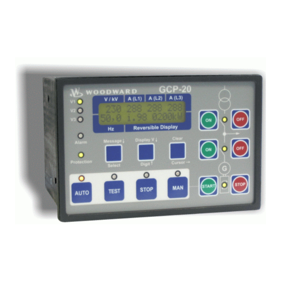
Manual 37128A GCP-20 Series - Genset Control Chapter 8. Display and Operation Front Panel ≡≡≡≡≡≡≡≡≡≡≡≡≡≡≡≡≡≡≡≡≡≡≡≡≡ The pressure-sensitive membrane of the front panel consists of a plastic coating. All keys have been designed as touch-sensitive membrane switch elements. The display is an LC display, consisting of 2 rows each with 16 characters, with indirect green lighting. -
Page 61: Button Functions Overview
Manual 37128A GCP-20 Series - Genset Control ____________________________ Light emitting diodes Buttons _____________________________________ 13 > "Message ↓" ....advance of the message 1 > "V1" ............. voltage L1 2 > "V2" ............. voltage L2 13 > "Selection".........confirm selection 3 > "V3" ............. voltage L3 14 >... -
Page 62: Leds
Manual 37128A GCP-20 Series - Genset Control .. sequence for pressing the buttons LEDs ≡≡≡≡≡≡≡≡≡≡≡≡≡≡≡≡≡≡≡≡≡≡≡≡≡ NOTE The LEDs can be checked via a lamp test. In order to achieve this, press the button "message ↓" and repeat pressing the button until the display "00.0 LED-TEST" appears in the bottom line of the dis- play. - Page 63 Manual 37128A GCP-20 Series - Genset Control MCB on Reply: MCB is closed / Mains parallel [GCP-20/22] Mains parallel [GCP-21] [GCP-20/22] Items with two power circuit breakers: The "MCB ON" LED Color: green indicates that the mains power circuit breaker is closed.
-
Page 64: Push-Buttons
Manual 37128A GCP-20 Series - Genset Control Push-Buttons ≡≡≡≡≡≡≡≡≡≡≡≡≡≡≡≡≡≡≡≡≡≡≡≡≡ In order to facilitate the setting of the parameters the buttons are equipped with a "AUTOROLL-function". It al- lows to switch to the next setting and configuration screens, the digits, or the cursor position. The "AUTOROLL"... -
Page 65: Operation Of The Power Circuit Breakers
Manual 37128A GCP-20 Series - Genset Control Operation of The Power Circuit Breakers Close MCB / open MCB (only available in [GCP-20/22]) MCB ON / MCB OFF only [GCP-20/22] Note: Only enabled if operating mode MANUAL or TEST has been se- Color: green/red lected. - Page 66 Manual 37128A GCP-20 Series - Genset Control TEST Operating mode TEST Color: blue By actuating the "TEST" push-button, the engine is started, and engine monitoring is activated. No power circuit breakers are operated. This is car- ried out in the event of mains failure and when emergency power is switched on.
-
Page 67: Lc Display
Manual 37128A GCP-20 Series - Genset Control LC Display ≡≡≡≡≡≡≡≡≡≡≡≡≡≡≡≡≡≡≡≡≡≡≡≡≡ LC Display LC display The LC display shows messages and values, depending on the respective mode applied. In configuration mode, the individual parameters are dis- played and changed. In Automatic mode the operating variables (e. g. volt- ages and currents) can be called up. -
Page 68: Chapter 9. Configuration
• CAN bus (CiA) = 125 kBaud Because of functional enhancements within the controls of the GCP-20 Series it is necessary to use a new version of the configuration software LeoPC1. This version must be at least 3.1 or higher. If the LeoPC1 software you currently use has an older version the latest version can be ordered at our technical sales or can be downloaded on our homepage at http://www.woodward.com/software. -
Page 69: Service Display
Manual 37128A GCP-20 Series - Genset Control Service Display ≡≡≡≡≡≡≡≡≡≡≡≡≡≡≡≡≡≡≡≡≡≡≡≡≡ Service display ON/OFF Service display ON....The following three screens are displayed (the voltages and frequen- only visible, while cies of the busbar, the mains and the generator are displayed). In ad-... -
Page 70: Status Of Power Circuit Breakers And Relays
Manual 37128A GCP-20 Series - Genset Control Status of Power Circuit Breakers and Relays Status of power circuit breakers and relays of the controllers Rel.: The display shows the actual relay states of the controller outputs and the signals to only visible, while the power circuit breakers. -
Page 71: Basic Configuration
Manual 37128A GCP-20 Series - Genset Control Basic Configuration ≡≡≡≡≡≡≡≡≡≡≡≡≡≡≡≡≡≡≡≡≡≡≡≡≡ Configuration Access The control is equipped with a three-level code and configuration hierarchy, which enables it to access various configuration screens for different users. A distinction is made between: Code level 0 (CS0) - User: Third party This code level enables no access to the parameters. -
Page 72: Direct Configuration
Manual 37128A GCP-20 Series - Genset Control Parameter 4 Generator number (number of the control on the CAN bus) 1 to 8 Generator number If several controls are available and these are coupled via a CAN bus, a different number must be assigned to each control for differentiation purposes. The genera- tor number 1 should be assigned even in the case of a single control. -
Page 73: Measuring
Manual 37128A GCP-20 Series - Genset Control Measuring ≡≡≡≡≡≡≡≡≡≡≡≡≡≡≡≡≡≡≡≡≡≡≡≡≡ WARNING The following values must be entered correctly for the generator to be monitored. Failure to do so may lead to incorrect measuring resulting in damage to or destruction of the generator and/or personal in- jury or death. -
Page 74: Rated Voltage Values
Manual 37128A GCP-20 Series - Genset Control Parameter 10 Secondary busbar voltage transformer [1] 50 to 125 V; [4] 200 to 440 V Bus.volt.transf. This value corresponds to the secondary voltages of the PTs, which are di- secondary 000V rectly connected to the control. -
Page 75: Generator Current
Manual 37128A GCP-20 Series - Genset Control Generator Current Parameter 15 Generator CTs 10 to 7,000/{X} A Current transf. The input of the CT ratio is necessary in order to display and control the actual val- generator 0000/x ues. The CT ratio must be selected so that, at maximum power, at least 60 % of the CT nominal current flows. -
Page 76: Mains Current/Mains Power Measurement
Manual 37128A GCP-20 Series - Genset Control Mains Current/Mains Power Measurement The two following chapters Mains Power Measurement Via CT and Mains Power Measurement Via Analog In- put (Option In20) are displayed alternatively and according to the measurement. If no measurement of the mains power was requested via a 0/4 to 20 mA analog input, the measurement is always effected via a power trans- former. -
Page 77: Password Configuration
Manual 37128A GCP-20 Series - Genset Control Password Configuration NOTE Once a password has been set, it will not change unless a person alters that parameter with access to, it regardless of how often the configuration mode is accessed. If an incorrect code number is entered, the code level is set to CS0 and the control is therefore locked for external users. -
Page 78: Real Power Controller, Set Point Values [Gcp-21/22]
Manual 37128A GCP-20 Series - Genset Control Real Power Controller, Set Point Values [GCP-21/22] These screens appear only if the generator real power controller has been configured to "ON". NOTE The fixed-value power control does not take into account the mains interchange point. If excess power is generated, it will be exported to the mains. -
Page 79: Frequency Controller
Manual 37128A GCP-20 Series - Genset Control Frequency Controller NOTE The initial state refers always to the complete range of the actuator signal (0 to 100%) regardless of the min/max limitations. A possible range limitation of the actuator signal is considered for active controllers. - Page 80 Manual 37128A GCP-20 Series - Genset Control Parameter 35 f controller: set point ramp 2 to 50 Hz/s Freq.controller The different set point values are supplied to the controller via this ramp. The slope ramp 00Hz/s of the ramp is used to alter the rate at which the controller modifies the set point value.
-
Page 81: Voltage Controller
Manual 37128A GCP-20 Series - Genset Control Voltage Controller NOTE The initial state refers always to the complete range of the actuator signal (0 to 100%) regardless of the min/max limitations. A possible range limitation of the actuator signal is considered for active controllers. - Page 82 Manual 37128A GCP-20 Series - Genset Control Parameter 48 V controller: dead band [1] 0.1 to 15.0 V; [4] 0.5 to 60.0 V Volt.controller Isolated operation The generator set point voltage is controlled in such a manner dead band 00.0V...
-
Page 83: Power Factor Controller [Gcp-21/22]
Manual 37128A GCP-20 Series - Genset Control Power Factor Controller [GCP-21/22] Parameter 54 Power factor controller: activation ON/OFF Pow.fact.contr. ON....In a mains parallel operation automatic control of the power factor is carried out. If there are excessively low currents (secondary current less than 5 % I ) the power factor cannot be accurately measured. -
Page 84: Real Power Controller [Gcp-21/22]
Manual 37128A GCP-20 Series - Genset Control Parameter 60 Power factor controller: derivative-action time 0.00 to 6.00 s Pow.fact.contr. The derivative-action time T identifies the D part of the PID controller. By in- Deriv.time 0.00s creasing this parameter, the stability of the system is increased. The controller will... - Page 85 Manual 37128A GCP-20 Series - Genset Control External Set Point Value (Option The generator real power may be monitored via an analog input if this analog inputs is utilized as set point value a 0/4 to 20 mA input. Parameter 65...
- Page 86 Manual 37128A GCP-20 Series - Genset Control Parameter 70 P controller: gain factor 0.1 to 99.9 Power controller The gain factor K influences the operating time of the relays. By increasing the Gain Kp 00.0 gain, the response is increased to permit larger corrections to the variable to be con- trolled.
-
Page 87: Load And/Or Var Sharing
Manual 37128A GCP-20 Series - Genset Control Load and/or Var Sharing Parameter 77 kW/kvar sharing: load sharing ON/OFF Active power ON....Real power is shared between multiple generators operating in paral- load-share lel. The generator outputs are distributed depending on the config- ured value. -
Page 88: Automatic
Manual 37128A GCP-20 Series - Genset Control Automatic ≡≡≡≡≡≡≡≡≡≡≡≡≡≡≡≡≡≡≡≡≡≡≡≡≡ Parameter 81 Configuration of automatic YES/NO Configure Parameters are grouped together in blocks to permit quicker navigation through the automatic large number of configuration screens. Selecting "YES" or "NO" has no effect if controlling or monitoring is performed. - Page 89 Manual 37128A GCP-20 Series - Genset Control Load-Dependent Start/Stop in Mains Parallel Operation Parameter 82 Load dependent start/stop: enable via terminal 3 ON/OFF Loadd.start/stop ON....If the control input "Automatic 1" (terminal 3) is enabled, an auto- at ter.3 matic start/stop is performed on the basis of the generator set point real power 1 (Parameter 26).
- Page 90 Manual 37128A GCP-20 Series - Genset Control Stopping Hysteresis NOTE The following Parameter 87 is used to determine stopping hysteresis for single gensets in mains paral- lel operation, for generators connected to other generators in mains parallel operation, and in isolated operation in parallel with other gensets.
- Page 91 Manual 37128A GCP-20 Series - Genset Control Load Sharing with Other Generators in Mains Parallel Operation The load-dependent start/stop function is activated for every control when the following criteria has been met: • the operation mode AUTOMATIC has been selected •...
- Page 92 Manual 37128A GCP-20 Series - Genset Control Mains Parallel Operation(Mains Interchange (Import/Export) Real Power Control with Several Generators) General Case 3: Start of the first engine All GCBs are open. If [P > P ] the first engine is started.
- Page 93 Manual 37128A GCP-20 Series - Genset Control 180 kW), negative deviation from the pre-specified reserve power has occurred. As a result of this, the next engine is started. Case 5: Generator real power of each individual generators, at which one engine is stopped: <...
- Page 94 Manual 37128A GCP-20 Series - Genset Control Isolated Operation in Parallel with Other Generators The load-dependent start/stop function is activated for every control when the following criteria has been met: • the operation mode AUTOMATIC has been selected • all parameters, such as start power (Parameter 84), stop power (Parameter 87), start delay (Parameter 85),...
-
Page 95: Temperature-Dependent Start/Stop (Option Tz)
Manual 37128A GCP-20 Series - Genset Control Two generators in an isolated operation are used in parallel with other generators. One generator should always be in operation. = 200 kW Rated real power of a genset. rated = 60 kW Reserve.isolated... -
Page 96: Remote Control Via Interface (Option Sb/Sf)
Manual 37128A GCP-20 Series - Genset Control Parameter 96 CHP deactivation temperature 0 to 255°C Temperature of The temperature value at which the genset is to be stopped is entered in this screen. Stop 000°C If the value is reached or exceeded, the genset stops automatically. - Page 97 Manual 37128A GCP-20 Series - Genset Control Set Point Specification via Interface X1 to X5 (Option SF) Parameter 100 Control via interface COM X1 to X5 ON/OFF serial Control ON....Control via the interface is enabled if the direct configuration (Para- com X1X5 meter 5) has been configured as "OFF", the control via Y1Y5 (Para-...
-
Page 98: Breaker
Manual 37128A GCP-20 Series - Genset Control Breaker ≡≡≡≡≡≡≡≡≡≡≡≡≡≡≡≡≡≡≡≡≡≡≡≡≡ Parameter 103 Configuration of the breakers YES/NO Configure Parameters are grouped together in blocks to permit quicker navigation through the breaker large number of configuration screens. Selecting "YES" or "NO" has no effect if controlling or monitoring is performed. - Page 99 Manual 37128A GCP-20 Series - Genset Control Overview [GCP-20/22] STOP TEST MANUAL AUTOMATIC EXTERNAL: Breaker logic "External" The MCB and the GCB are operated in MANUAL operation mode only in this breaker logic mode. In a mains parallel opera- tion, uncoupling from the mains is carried out via the MCB or the GCB in the event of a mains failure. The breakers will not automatically close in emergency power operation.
- Page 100 Manual 37128A GCP-20 Series - Genset Control STOP TEST MANUAL AUTOMATIC CLOSED TRANS.: Breaker logic "Closed transition / make-before-brake / overlap synchronization" The MCB and the GCB are synchronized, in order to avoid a dead busbar in this breaker logic mode. Immediately after the synchronization of one breaker, the other is opened.
-
Page 101: Start/Stop Ramp, Open Gcb With F2 Alarm
Manual 37128A GCP-20 Series - Genset Control Overview [GCP-21] STOP TEST MANUAL AUTOMATIC EXTERNAL: Breaker logic "External" The GCB is never synchronized in this operation mode. Decoupling from the mains when in a mains parallel operation is car- ried out via the GCB in the event of mains faults. The breaker will not automatically close in emergency power operations. -
Page 102: Gcb Impulse/Constant Pulse
Manual 37128A GCP-20 Series - Genset Control Parameter 107 Max. perm. time with F2 alarms for starting a further engine 0 to 999 s Open GCB with F2 Prerequisite: Load sharing (Parameter 77) and automatic start/stop (Parameter 82 or max.time 000s Parameter 83) are configured to "ON". -
Page 103: Open/Close Gcb
Manual 37128A GCP-20 Series - Genset Control • open GCB/MCB: 9 Opening pulse GCB/MCB enabled; 10 Inherent delay; 11 Reply GCB/MCB; 12 Time delay (GCB: 2 s; MCB: 0.8 s); 13 Opening pulse disabled. • Beaker logic: 'Constant' 'Constant' logic (GCB only): 1 Enable; 2 Synchronization; 3 Connect time reached: •... -
Page 104: Synchronization (With Synchronous Generators Only)
Manual 37128A GCP-20 Series - Genset Control Synchronization (With Synchronous Generators Only) CAUTION Please consider that units with a software older than V1.0700 do not have an internal rotating field monitoring. Units below V1.0700 assume always a clockwise phase rotation direction of all three voltage systems, which are measured. -
Page 105: Synchronization Time Monitoring (With Synchronous Generators Only)
Manual 37128A GCP-20 Series - Genset Control Synchronization Time Monitoring (With Synchronous Generators Only) If the following parameter (Parameter 117) is configured to "ON", synchronization time monitoring is per- formed: If the synchronization of the GCB or MCB [GCP-20/22] is initiated, the timer is started following the termination of the delayed engine monitoring. -
Page 106: Connection Functions (With Induction/Asynchronous Generators Only)
Manual 37128A GCP-20 Series - Genset Control Parameter 122 Dead bus closing of the MCB ON/OFF MCB dead bus op. ON ....A dead bus closing of the MCB is performed in the event of a de- energized busbar and an open GCB. The subsequent screens of this [GCP-20/22] only function are displayed. -
Page 107: Connect Time Monitoring (With Induction/Asynchronous Generators Only)
Manual 37128A GCP-20 Series - Genset Control Connect Time Monitoring (With Induction/Asynchronous Generators Only) If Parameter 127 is configured to "ON", closing time monitoring is performed: A timer is started when the clos- ing of the GCB is initiated following the termination of the delayed engine monitoring. If the breaker has not closed following the expiration of the configured time, an F1 alarm message is issued. -
Page 108: Mains Decoupling
Manual 37128A GCP-20 Series - Genset Control Parameter 130 MCB monitoring ON/OFF Supervision MCB ON ....Monitoring of the MCB is performed except when the breaker logic is configured as "EXTERNAL". If the breaker cannot be closed after [GCP-20/22] only five attempts, an alarm message is issued. The relay with the parame- ter 75 is energized. -
Page 109: Emergency Power (Amf)
Manual 37128A GCP-20 Series - Genset Control Emergency Power (AMF) ≡≡≡≡≡≡≡≡≡≡≡≡≡≡≡≡≡≡≡≡≡≡≡≡≡ Parameter 133 Configuration of the emergency power (AMF) YES/NO Configure Parameters are grouped together in blocks to permit quicker navigation through the emerg.run large number of configuration screens. Selecting "YES" or "NO" has no effect if controlling or monitoring is performed. -
Page 110: Protection
Manual 37128A GCP-20 Series - Genset Control Protection ≡≡≡≡≡≡≡≡≡≡≡≡≡≡≡≡≡≡≡≡≡≡≡≡≡ Parameter 137 Configuration of the protection YES/NO Configure Parameters are grouped together in blocks to permit quicker navigation through the monitoring large number of configuration screens. Selecting "YES" or "NO" has no effect if controlling or monitoring is performed. -
Page 111: Mains Power Monitoring [Gcp-21/22]
Manual 37128A GCP-20 Series - Genset Control Mains Power Monitoring [GCP-21/22] It is possible to monitor one configurable mains power limit value. It is possible to output the tripping to one of the freely configurable relays by means of the relay manager (relay manager function 67). This function makes it possible to initiate external load shedding. -
Page 112: Generator Overload Monitoring
Manual 37128A GCP-20 Series - Genset Control Generator Overload Monitoring NOTE All percentage values refer to a percentage of the generator rated power (Parameter 17; page 75). Function: "Positive real power not within the permissible range" - The single-phase or three-phase measured generator real power is above the configured limit value of the real power. -
Page 113: Generator Reverse/Reduced Power Monitoring
Manual 37128A GCP-20 Series - Genset Control Generator Reverse/Reduced Power Monitoring NOTE All percentage values refer to a percentage of the generator rated power (Parameter 17; page 75). Function: "Real power not within the permissible range" - The real power measured in a single-phase or in a three-phase system is below the configured limit value for the minimum load or below the configured value for reverse power. -
Page 114: Unbalanced Load Monitoring
Manual 37128A GCP-20 Series - Genset Control Unbalanced Load Monitoring NOTE All percentage values refer to a percentage of the generator rated power (Parameter 18; page 75). Function: "Generator load imbalance not within the permissible range" - The percentage threshold value speci- fies the permissible deviation of one phase current to the arithmetic mean value of all three phase currents. -
Page 115: Time-Overcurrent Monitoring
Manual 37128A GCP-20 Series - Genset Control Time-Overcurrent Monitoring NOTE All percentage values refer to a percentage of the generator rated power (Parameter 18; page 75). Function: The GCP-20 utilizes a two tier time-overcurrent monitoring with separate adjustable time delays. The threshold values and delays can be selected so that the monitored current level is independent from the tripping time. -
Page 116: Generator Frequency Monitoring
Manual 37128A GCP-20 Series - Genset Control Generator Frequency Monitoring Function: "Generator frequency not within the permissible range" - The generator frequency is outside of the limit values set for overfrequency or underfrequency. The engine is shut down immediately (class F3 alarm), and an alarm message is displayed. -
Page 117: Generator Voltage Monitoring
Manual 37128A GCP-20 Series - Genset Control Generator Voltage Monitoring The line-to-line (wye) voltage is monitored. Function: "Generator voltage not within the permissible range" - If one or more phases of the generator voltage exceeds the limit values set for overvoltage or undervoltage, the engine is shut down immediately (class F3 alarm) and an alarm message is displayed. -
Page 118: Mains Frequency Monitoring
Manual 37128A GCP-20 Series - Genset Control Mains Frequency Monitoring Monitoring the mains frequency is absolutely vital if a generator is operated in conjunction with the infinite grid. In the event of mains failure (e.g. utility power outage) the generator that is operating in parallel with the utility must be automatically disconnected from the mains. -
Page 119: Mains Voltage Monitoring
Manual 37128A GCP-20 Series - Genset Control Mains Voltage Monitoring Monitoring the mains voltage is absolutely vital if a generator is operated in conjunction with the infinite grid. In the event of mains failure (e.g. utility power outage) the generator that is operating in parallel with the utility must be automatically disconnected from the mains. -
Page 120: Phase/Vector Shift Monitoring Dϕ/Dt
Manual 37128A GCP-20 Series - Genset Control Phase/Vector Shift Monitoring dϕ/dt A phase/vector shift is a sudden change in the voltage curve that is caused by a large generator load change. The measuring circuit detects a change in a single sine wave. This sine wave is compared with a calculated mean value from previous measurements. -
Page 121: Battery Voltage Monitoring
Manual 37128A GCP-20 Series - Genset Control Battery Voltage Monitoring Parameter 188 Battery voltage monitoring: Threshold value 8 to 35 V Batt.undervolt. If the measured value falls below this threshold value for at least the delay time U < 00.0V (Parameter 189), the following alarm class is issued. -
Page 122: Figure 9-3: No/Nc Logic
Manual 37128A GCP-20 Series - Genset Control monitored though other means than the state of the relay. Closed circuit current (NC): The relay is disabled (i.e. in idle state) when current flows through the coil. If a loss of the supply voltage occurs, a change of state will occur in the relay and a triggering of fault conditions will occur. -
Page 123: Configuring The Text For The Discrete Inputs
Manual 37128A GCP-20 Series - Genset Control Parameter 194 Alarm class of the discrete alarm inputs 1 to 4 F0 to F3 Dig.input 1234 Different alarm classes can be assigned to each discrete alarm input. The alarm error class 0000 classes are listed below. -
Page 124: Control Inputs
Manual 37128A GCP-20 Series - Genset Control Control Inputs Acknowledge firing speed via terminal 62 Parameter 196 Firing speed reached via terminal 62 ON/OFF Firing speed by OFF ....This terminal is used as an alarm input. Term. 62 ON ....Configuring the starting sequence logic: If Parameter 191 is configured to "E", the discrete input utilizes... - Page 125 Manual 37128A GCP-20 Series - Genset Control Change breaker logic via terminal 64 Parameter 198 Open transition via terminal 64 ON/OFF Open transition OFF....This terminal is used as an alarm input. by Term64 ON....This terminal is used as control input.
-
Page 126: Terminal 6
Manual 37128A GCP-20 Series - Genset Control Terminal 6 ATTENTION The various functions of terminal 6 are enabled at different signal levels! Parameter 201 Function of terminal 6 Function term.6 This parameter is used to assign a function to the terminal 6 discrete input. The fol-... -
Page 127: Analog Inputs (Option T4)
Manual 37128A GCP-20 Series - Genset Control Analog Inputs (Option ≡≡≡≡≡≡≡≡≡≡≡≡≡≡≡≡≡≡≡≡≡≡≡≡≡ Parameter 202 Configuration of analog inputs YES/NO Configure Parameters are grouped together in blocks to permit quicker navigation through the analg.inp. large number of configuration screens. Selecting "YES" or "NO" has no effect if... - Page 128 Manual 37128A GCP-20 Series - Genset Control Pt100 Input (Analog Input [T1] to [T4]) Pt100 inputs may be measured here. The analog input is displayed with its description. Two threshold limits can be monitored. The first level initiates a class F1 alarm, the second level initiates a class F3 alarm.
- Page 129 Manual 37128A GCP-20 Series - Genset Control Pt1000 Input (Analog Input [T1] to [T4]) Pt1000 inputs may be measured here. The analog input is displayed with its description. Two threshold limits can be monitored. The first level initiates a class F1 alarm, the second level initiates a class F3 alarm.
- Page 130 Manual 37128A GCP-20 Series - Genset Control PTC Input (Analog Input [T1] to [T4]) PTC inputs may be measured here. The analog input is displayed with its description. Two threshold limits can be monitored. The first level initiates a class F1 alarm, the second level initiates a class F3 alarm.
-
Page 131: Figure 9-6: Vdo Transmitter 323.805/001/001 (Slope)
Manual 37128A GCP-20 Series - Genset Control VDO Input 'Temperature' (Analog Input [T1 to T4]) VDO inputs may be measured here (the input has been calibrated to the VDO sender 323.805/001/001 (0 to 380 ohm, 40 to 120 °C). The analog input is displayed with its description. Two threshold levels can be moni- tored. - Page 132 Manual 37128A GCP-20 Series - Genset Control Parameter 226 VDO input, temperature; delay for limit values of class F1 and F3 alarm 0 to 999 s Delay In order to initiate an alarm, the measured value must be over or under (dependent...
- Page 133 Manual 37128A GCP-20 Series - Genset Control Parameter 233 VDO input, pressure; limit value for class F3 alarm 0.0 to 10.0 bar Limit shutdown If the measured value exceeds or falls below this configured threshold value (de- value 00.0bar pendent upon Parameter 238) for at least the delay time (Parameter 237), the fol- lowing alarm class is initiated.
- Page 134 Manual 37128A GCP-20 Series - Genset Control Scaleable analog input 0/4 to 20 mA (analog input [T1] to [T4]) 0/4 to 20 mA sensors may be measured here. A description and an engineering unit may be assigned to the input.
- Page 135 Manual 37128A GCP-20 Series - Genset Control Parameter 247 0/4 to 20 mA input; monitoring for ... high limit mon. / low limit mon. Monitoring for A fault condition is recognized when the measured value has exceeded or fallen be- ---------------- low the threshold value (Parameter 244 or Parameter 245).
-
Page 136: Output Configuration
Manual 37128A GCP-20 Series - Genset Control Output Configuration ≡≡≡≡≡≡≡≡≡≡≡≡≡≡≡≡≡≡≡≡≡≡≡≡≡ Parameter 250 Configuration of the outputs YES/NO Configure Parameters are grouped together in blocks to permit quicker navigation through the outputs large number of configuration screens. Selecting "YES" or "NO" has no effect if controlling or monitoring is performed. -
Page 137: Relay Manager
Manual 37128A GCP-20 Series - Genset Control Relay Manager The relay manager enables the assignment of an arbitrary combination of functions to each relay of the termi- nals 33 to 36, 37, 38 and 47 to 48. In order to achieve this, each function of the control has its own number. A text, which describes a logical condition that energizes the relay, must now be entered in the configuration menu for each relay. -
Page 138: Engine Configuration
Manual 37128A GCP-20 Series - Genset Control Engine Configuration ≡≡≡≡≡≡≡≡≡≡≡≡≡≡≡≡≡≡≡≡≡≡≡≡≡ Parameter 256 Configuration of the engine YES/NO Configure Parameters are grouped together in blocks to permit quicker navigation through the engine large number of configuration screens. Selecting "YES" or "NO" has no effect if controlling or monitoring is performed. -
Page 139: Start/Stop Sequence 'Gas Engine
Manual 37128A GCP-20 Series - Genset Control Start/Stop Sequence 'Gas Engine' Time jump without Pickup active: < 15 Hz 1500 1/min min. speed starter is not reached Start frequency f-contr. + time ZD (1) min. speed starter (Pickup ON) [1/min] (2) - Page 140 Manual 37128A GCP-20 Series - Genset Control Starting Sequence If the control is equipped with a three-position frequency controller, a continuous signal (time adjustable via Parameter 266) is output prior to starting the engine at the "Frequency lower" relay output. The starter is then en- abled.
- Page 141 Manual 37128A GCP-20 Series - Genset Control Parameter 265 Gas engine; approach low-idle position ON/OFF freq. low before If this function is enabled and the control is equipped with a three-step frequency start controller, the command "lower engine speed" is issued for the time configured in with three-step controllers only Parameter 266 before the starter is engaged.
-
Page 142: Start/Stop Sequence 'Diesel Engine
Manual 37128A GCP-20 Series - Genset Control Start/Stop Sequence 'Diesel Engine' 1500 1/min Start frequency f-contr. + time Speed governor Approach idle gas position Engine monitoring activated Start request Start relay Pre-glow 0,5 s 0,5 s Starter Delayed engine monitoring 00s... - Page 143 Manual 37128A GCP-20 Series - Genset Control Stopping Sequence When the start request is terminated, a power reduction is performed (if the real power controller is enabled, Parameter 61). Once the GCB has opened, an engine cool down is performed (Parameter 273). When the engine cool down period expires, the fuel relay is de-energized and the engine is stopped.
-
Page 144: Cool Down
Manual 37128A GCP-20 Series - Genset Control Cool Down Parameter 273 Engine; cool down time 0 to 999 s Cooldown time If the engine performs a normal shutdown (i.e. STOP mode initiated) or stoppage 000s by means of a class F2 alarm has been initiated, an engine cool down period with an open GCB and frequency control is performed for this time. -
Page 145: Delayed Engine Monitoring And Firing Speed
Manual 37128A GCP-20 Series - Genset Control Delayed Engine Monitoring and Firing Speed Figure 9-9: Delayed engine monitoring Parameter 274 Engine; delayed engine monitoring 1 to 99 s Delayed engine Delay between reaching the firing speed and monitoring of selected alarms (e.g. oil monitoring pressure, generator underfrequency, etc.). -
Page 146: Pick-Up (Mpu)
Manual 37128A GCP-20 Series - Genset Control Pick-Up (MPU) Measuring the engine speed can be performed alternatively by means of a Magnetic Pickup, the generator fre- quency, or a tacho generator. Refer to the wiring diagram that pertains to your specific controller under Wiring Diagrams. -
Page 147: Counter Configuration
Manual 37128A GCP-20 Series - Genset Control Counter Configuration ≡≡≡≡≡≡≡≡≡≡≡≡≡≡≡≡≡≡≡≡≡≡≡≡≡ Parameter 279 Configuration of the counters YES/NO Configure Parameters are grouped together in blocks to permit quicker navigation through the counters large number of configuration screens. Selecting "YES" or "NO" has no effect if controlling or monitoring is performed. -
Page 148: Start Counter
Manual 37128A GCP-20 Series - Genset Control Start Counter Parameter 282 Counter; number of engine starts 0 to 32,749 Start counter The start counter is used to display how many times the engine has been started. 00000 Following each starting attempt the start counter is increased by one. This permits the user to display the correct number of starts if this controller is used on an older engine, a starter is replaced, or this controller is to replace an older controller. -
Page 149: Chapter 10. Commissioning
Manual 37128A GCP-20 Series - Genset Control Chapter 10. Commissioning DANGER - HIGH VOLTAGE When commissioning the control, please observe all safety rules that apply to the handling of live equipment. Ensure that you know how to provide first aid in the event of an uncontrolled release of en- ergy and that you know where the first aid kit and the nearest telephone are. - Page 150 Manual 37128A GCP-20 Series - Genset Control "AUTO" operation mode (press the "AUTO" push-button): Applying the automatic control inputs and the engine start request can now carry out automatic starting with subsequent synchronization. Check synchronization: Check the generator and the generator busbar rotating fields. Check the connect command with a zero voltmeter (determination of the phase angle) at the generator power circuit breaker (GCB).
-
Page 151: Appendix A. Technical Data
Manual 37128A GCP-20 Series - Genset Control Appendix A. Technical Data Name plate ----------------------------------------------------------------------------------------------------- Serial number (numerical) Date of production (YYMM) Serial number (Barcode) Item number Item revision number Details Technical data Type Description (long) Type Description (short) UL sign (Example of a typical name plate) Measuring values, voltages------------------------------------------------------------------------------ /Δ... - Page 152 Manual 37128A GCP-20 Series - Genset Control Discrete inputs ---------------------------------------------------------------------- galvanically isolated Input range (V )........Rated voltage 12/24 Vdc (4 40 Vdc) Cont, digital input Input resistance .....................approx. 6.8 kΩ Relay outputs -------------------------------------------------------------------------------- potential free Contact material ......................AgCdO General purpose (GP) (V Cont, relay output AC..........2.00 Aac@250 Vac...
- Page 153 Manual 37128A GCP-20 Series - Genset Control Interface -------------------------------------------------------------------------------------------------------- Service interface Version ........................RS-232 Signal level ........................5 V Level conversion and isolation by using DPC (P/N 5417-557) CAN bus interface ....................isolated Isolation voltage ....................1,500 Vdc Version ........................CAN bus Internal line termination .................. Not available Housing --------------------------------------------------------------------------------------------------------- Type....................APRANORM DIN 43 700...
-
Page 154: Appendix B. Common
Manual 37128A GCP-20 Series - Genset Control Appendix B. Common Conversion Factors ≡≡≡≡≡≡≡≡≡≡≡≡≡≡≡≡≡≡≡≡≡≡≡≡≡ Conversion Factors: Temperature °C °F °F °C ° − ° Value ° ° ° × ° ° ° Value ° ° Conversion Factors: Pressure Value × Value Page 154/190 ©... -
Page 155: Appendix C. Analog Output Manager (Option A2)
Manual 37128A GCP-20 Series - Genset Control Appendix C. Analog Output Manager (Option NOTE The functions listed below can only be output correctly if the existing version of the control permits this. Func- Output Value Input of the two limit values tion The analog output is disabled. - Page 156 Manual 37128A GCP-20 Series - Genset Control Func- Output Value Input of the two limit values tion Speed via Pickup [min Lower speed e.g. 0000 rpm 100% Upper speed e.g. 3000 rpm Analog input [T1] [°C] or [°F] or freely scaleable Analog input [T2] [°C] or...
-
Page 157: Figure 10-1: Analog Outputs - Power Factor Scaling
Manual 37128A GCP-20 Series - Genset Control Definition of power factor scaling: According to the scaling of the analog output, the power factor can be out- put within the range from capacitive values ranging from c0.00 via power factor ϕ = 1 to inductive values up to i0.00. -
Page 158: Appendix D. Relay Manager
Manual 37128A GCP-20 Series - Genset Control Appendix D. Relay Manager Parameter Explanation Output special version Alarm class 1 Alarm class 2 Alarm class 3 Firing speed reached / (motor runs) Mains failure (alarm) Battery undervoltage Operating mode AUTOMATIC Operating mode MANUAL... - Page 159 Manual 37128A GCP-20 Series - Genset Control Parameter Explanation Output special version Mains parallel operation is desired: Clear blocking of GCB ↔ MCB Relay is set if the MCB or the GCB are synchro- nized and if MCB + GCB are closed (NPB) Overcurrent I/t or generator overcurrent level 2 UMZ Introduce load-shedding: Add-on / Sync.
-
Page 160: Appendix E. Interface Protocol (Options Su/Sb/Sf)
Manual 37128A GCP-20 Series - Genset Control Appendix E. Interface Protocol (Options SU/SB/SF) Transmission Telegram (Options SU/SB) Interface Y1Y5 Only ≡≡≡≡≡≡≡≡≡≡≡≡≡≡≡≡≡≡≡≡≡≡≡≡≡ Number Content (words) Unit/Bit Comment 3964 MOD bus Telegram type Telegram call sign (00, 01) Generator voltage L12 (02, 03) - Page 161 Manual 37128A GCP-20 Series - Genset Control Number Content (words) Unit Comment 3964 MOD bus Alarm message 1 Bit 15 = 1 \ (48, 49) Internal internal alarm Bit 14 = 1 / Bit 13 = 1 \ Internal 0000H = no troubles are present...
- Page 162 Manual 37128A GCP-20 Series - Genset Control Number Content (words) Unit Comment 3964 MOD bus Alarm message 4 Bit 15 = 1 \ (54, 55) Terminal 68 discrete inputs Bit 14 = 1 / Bit 13 = 1 \ Terminal 67...
- Page 163 Manual 37128A GCP-20 Series - Genset Control Number Content (words) Unit Comment 3964 MOD bus Malfunction message 7 Bit 15 = 1 \ (60, 61) Internal Internal fault Bit 14 = 1 / Bit 13 = 1 \ Internal 0000H = no...
- Page 164 Manual 37128A GCP-20 Series - Genset Control Number Content (words) Unit Comment 3964 MOD bus Internal Reserve (70, 71) Internal (72, 73) alternatively according to setting (terminals 93/94/95) (74, 75) Analog input 1 alternatively according to setting (terminals 96/97/98) (76, 77)
-
Page 165: Receiving Telegram (Options Sb)
Manual 37128A GCP-20 Series - Genset Control Receiving Telegram (Options ≡≡≡≡≡≡≡≡≡≡≡≡≡≡≡≡≡≡≡≡≡≡≡≡≡ Receiving Telegram via RS-232/DK3964 Number Content (words) Unit Comment 3964 Remote start 00F0H remote start 000FH no remote start Remote stop 00F0H remote stop 000FH no remote stop Active power set point with control argument... -
Page 166: Remote Monitoring And Control Via Gateway Gw 4
Manual 37128A GCP-20 Series - Genset Control Remote Monitoring and Control via Gateway GW 4 (Option SF) Interface X1X5 Remote Monitoring via Gateway GW 4 (Transmission Telegram) Content (words) Unit Comment CAN-Bus (CAL)-Bus (Watchdog) Bit 15 = = 1 CAN Bus o.k. - Page 167 Manual 37128A GCP-20 Series - Genset Control Content (words) Unit Comment Control register 1 Bit 15 Internal Bit 14 Internal Bit 13 Internal Bit 12 Bit 11 Execution of acknowledgment of a F2/F3 alarm Bit 10 Bit 9 Execution of acknowledgment of a...
- Page 168 Manual 37128A GCP-20 Series - Genset Control Content (words) Unit Comment Generator frequency determined from Hz × 256 pickup Unit speed from pickup IGNEXPO Generator current in L1 A × 10 IGNEXPO Generator current in L2 A × 10 IGNEXPO Generator current in L3 A ×...
- Page 169 Manual 37128A GCP-20 Series - Genset Control Content (words) Unit Comment Generator active energy ( H.W.) Double word Generator active energy (L.W.) Battery voltage V × 10 Internal fault 1 Bit 15 = 1 \ Generator overfrequency Bit 14 = 1 /...
- Page 170 Manual 37128A GCP-20 Series - Genset Control Content (words) Unit Comment Internal fault 4 Bit 15 Analog input 1 - level 1 Bit 14 Bit 13 Analog input 1 - level 2 Bit 12 Bit 11 Analog input 2 - level 1...
- Page 171 Manual 37128A GCP-20 Series - Genset Control Content (words) Unit Comment External alarm Bit 15 Terminal 69 Bit 14 Bit 13 Terminal 70 Bit 12 Bit 11 Terminal 71 Bit 10 Bit 9 Terminal 72 Bit 8 Bit 7 Terminal 73...
- Page 172 Manual 37128A GCP-20 Series - Genset Control Meaning of the number 69 of the telegram " Currently active display message": Number Meaning GCB synchronization MCB synchronization GCB dead bus start MCB dead bus start Crank Start pause Cool down 000s (000s: the remaining time is displayed)
-
Page 173: Comments
Manual 37128A GCP-20 Series - Genset Control Remote Control via Gateway GW 4 (Receiving Telegram) The remote control data are only accepted by the GCP-20, if the unit is equipped with the corresponding option. Content (words) Unit Comment Active power setpoint with control argu-... -
Page 174: Coding Of The Power Set Point Value
Manual 37128A GCP-20 Series - Genset Control Procedure If the transmitter is ready for the data transmission, it informs the receiver by setting its control wire RTS into the "ON"-status. The prerequisite of this is that no data are received (CTS = "OFF"). The receiver registers this status and indicates its readiness for reception by switching its RTS line to "ON". -
Page 175: Appendix F. List Of Parameters
Manual 37128A GCP-20 Series - Genset Control Appendix F. List of Parameters Unit number P/N _____________________________ Rev _______________________________ Version GCP- _________________________________________________________________ Project _____________________________________________________________________ Serial number S/N _______________ Date ______________________________ Parameter Code Option Adjustment range Standard setting Customer settings 1. Line Text 2. Line level V x.xxxx... - Page 176 Manual 37128A GCP-20 Series - Genset Control Parameter Code Option Adjustment range Standard setting Customer settings 1. Line Text 2. Line level ONTROLLER CONFIGURATION YES/NO Configure Contr. C/I/E 0 to 3000 kW C 50 kW Power controller P set1 C/I/E 0 to 6,900 kW...
- Page 177 Manual 37128A GCP-20 Series - Genset Control Parameter Code Option Adjustment range Standard setting Customer settings 1. Line Text 2. Line level OAD MANAGEMENT CONFIGURATION YES/NO Configure automatic ON/OFF Loadd.Start/Stop at ter.3 ON/OFF Loadd.Start/Stop at ter.5 0 to 2,000 kW 15 kW MOP: gen.minimum...
- Page 178 Manual 37128A GCP-20 Series - Genset Control Parameter Code Option Adjustment range Standard setting Customer settings 1. Line Text 2. Line level MERGENCY POWER CONFIGURATION YES/NO Configure emerg.run ON/OFF Emergency power 0.5 to 99.9 s 3.0 s Emergency power start delay...
- Page 179 Manual 37128A GCP-20 Series - Genset Control Parameter Code Option Adjustment range Standard setting Customer settings 1. Line Text 2. Line level ONFIGURATION OF THE PROTECTIVE UNITS ≥V1.0700 phase-phase phase-phase Mains volt.monit. phase-neutral ON/OFF Mains voltage Monitoring <V1.070 20 to 130 440 V Mains overvolt.
- Page 180 Manual 37128A GCP-20 Series - Genset Control Parameter Code Option Adjustment range Standard setting Customer settings 1. Line Text 2. Line level ONFIGURATION OF DISCRETE INPUTS YES/NO Configure dig.inputs DDDD Dig. input 1234 function 0 to 9 0000 Dig. input 1234...
- Page 181 Manual 37128A GCP-20 Series - Genset Control Parameter Code Option Adjustment range Standard setting Customer settings 1. Line Text 2. Line level ONFIGURATION OF ANALOG INPUTS YES/NO T4 Configure analg. input Fahrenheit/Celsius Celsius °C °F °C °F T4 Temperature in:...
- Page 182 Manual 37128A GCP-20 Series - Genset Control Parameter Code Option Adjustment range Standard setting Customer settings 1. Line Text 2. Line level ONFIGURATION OF ANALOG INPUTS ON/OFF T4-2 Analog input 2 VDO Press. .. Name and unit bar/psi .. Pressure in...
- Page 183 Manual 37128A GCP-20 Series - Genset Control Parameter Code Option Adjustment range Standard setting Customer settings 1. Line Text 2. Line level ONFIGURATION OF ANALOG INPUTS ON/OFF T4-4 Temperature 4 Pt100/Pt1000 .. ***name**** 0 to 255 °C 80 °C .. limit warning 0 to 255 °C...
- Page 184 Manual 37128A GCP-20 Series - Genset Control Parameter Code Option Adjustment range Standard setting Customer settings 1. Line Text 2. Line level ONFIGURATION OF THE ENGINE YES/NO Configure engine 0 to 999 s Aux. services prerun 0 to 999 s Aux.
-
Page 185: Appendix G. Service Options
≡≡≡≡≡≡≡≡≡≡≡≡≡≡≡≡≡≡≡≡≡≡≡≡≡ If a control (or any part of an electronic control) is to be returned to Woodward for repair, please contact Wood- ward in advance to obtain a Return Authorization Number. When shipping the unit(s), attach a tag with the fol- lowing information: •... -
Page 186: Packing A Control
Stuttgart [+49 (0) 711 789 54-0]. They will help expedite the processing of your order through our distributors or local service facility. To expedite the repair process, contact Woodward in advance to obtain a Return Authoriza- tion Number, and arrange for issue of a purchase order for the unit(s) to be repaired. No work can be started until a purchase order is received. -
Page 187: How To Contact Woodward
+49 (0) 711 789 54-100 eMail: sales-stuttgart@woodward.com For assistance outside Germany, call one of the following international Woodward facilities to obtain the address and phone number of the facility nearest your location where you will be able to get information and service. Facility... -
Page 188: Engineering Services
GCP-20 Series - Genset Control Engineering Services ≡≡≡≡≡≡≡≡≡≡≡≡≡≡≡≡≡≡≡≡≡≡≡≡≡ Woodward Industrial Controls Engineering Services offers the following after-sales support for Woodward prod- ucts. For these services, you can contact us by telephone, by e-mail, or through the Woodward website. • Technical support •... -
Page 189: Technical Assistance
Manual 37128A GCP-20 Series - Genset Control Technical Assistance ≡≡≡≡≡≡≡≡≡≡≡≡≡≡≡≡≡≡≡≡≡≡≡≡≡ If you need to telephone for technical assistance, you will need to provide the following information. Please write it down here before phoning: Contact Your company ___________________________________________________ Your name ______________________________________________________... - Page 190 Phone +49 (0) 711 789 54-0 • Fax +49 (0) 711 789 54-100 sales-stuttgart@woodward.com Homepage http://www.woodward.com/smart-power Woodward has company-owned plants, subsidiaries, and branches, as well as authorized distributors and other authorized service and sales facilities throughout the world. Complete address/phone/fax/e-mail information for all locations is available on our website (www.woodward.com).
Need help?
Do you have a question about the GCP-20 Series and is the answer not in the manual?
Questions and answers