Table of Contents
Advertisement
Quick Links
Advertisement
Table of Contents

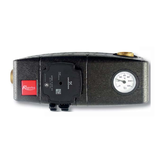
Summary of Contents for Regulus REGOMAT
- Page 1 Instruction Manual REGOMAT PUMP STATION - for boilers and fireplaces v. 1.0...
- Page 2 This pump station is intended for solid-fuel boilers and fireplaces. Description Regomat keeps the return temperature to a boiler (fireplace) at or above the valve opening temperature, which prevents low-temperature corrosion and boiler fouling. This prevents condensation and boiler tarring. The boiler then works with higher efficiency and its service life is extended.
- Page 3 4. Possible installation positions with a boiler This pump station comes in the version for horizontal installation on the left side of a boiler. However, it can be installed also into a vertical piping or on the right side of a boiler. When being installed horizontally on the right side of a boiler, the pump station needs to be turned by 180°...
- Page 4 5. Regomat components: » UPM3 heating system circulation pump, incl. a power cord and control cable » TSV3B thermostatic mixing valve (45 °C, 50 °C, 55 °C, 60 °C, 65 °C or 70 °C) » pump ball valve » thermometer »...
- Page 5 Valve pressure drop diagram During mixing, the valve pressure drop lies between the two curves, depending on the mixing ratio. UPM3 FLEX AS 25-70 Pump Design Wet-running circulation pump with G 6/4” M connection. Electrical data Power supply 230 V, 50 Hz Power input (min./max.) 2/52 W Current (min./max)
-
Page 6: Performance Curves
Performance curves Max. H Max. P Curve MAX. BOILER OUTPUT [kW] (upper graph) (lower graph) Curve valve, opening 25 W 45 °C 33 W 55 °C 39 W 65 °C 52 W Performance display DISPLAY STATE PERFORMANCE from P1max in % 1 flashing green LED STAND-BY MODE (EXTERNAL CONTROL... - Page 7 Settings display WARNING: LEDs may be turned by 180°, depending on the specific pump type. By pressing the button the display switches to “performance view” and the current settings will be shown by LEDs for 2 seconds. Error display seized pump too low power supply voltage electric fault Setting selection for UPM3...
- Page 8 PWM in (brown) N (blue) L (brown) PE (yellow-green) signal and power supply terminals socket for signal transmission (A) and power supply (B) 11/2016 REGULUS spol. s r.o. Do Koutů 1897/3 http://www.regulus.eu 143 00 Praha 4 E-mail: sales@regulus.eu CZECH REPUBLIC...


Need help?
Do you have a question about the REGOMAT and is the answer not in the manual?
Questions and answers