Advertisement
Quick Links
67532
Rev 02
SED9400
Installation and User Guide
Required tools
4 AA Batteries
Ruler
Phillips screwdriver
Outils additionnels (en fonction de l'application)
Wood
block
Hammer
1
Prepare the door and check dimensions
If drilling a new door, use the supplied template and the complete door drilling
instructions available at www.kwikset.com/doorprep
Measure to confirm that the hole in
A
the door is 2-1/8" (54 mm).
2-1/8"
54 mm
2
Install the latch and strike
Hold the latch in front of the door hole, with the
A
latch face flush against the door edge.
A
Is the slotted hole centered in the door hole?
YES
or
slotted hole
is centered
No adjustment is
Rotate latch
required. Proceed
face as shown to
to next step.
extend latch.
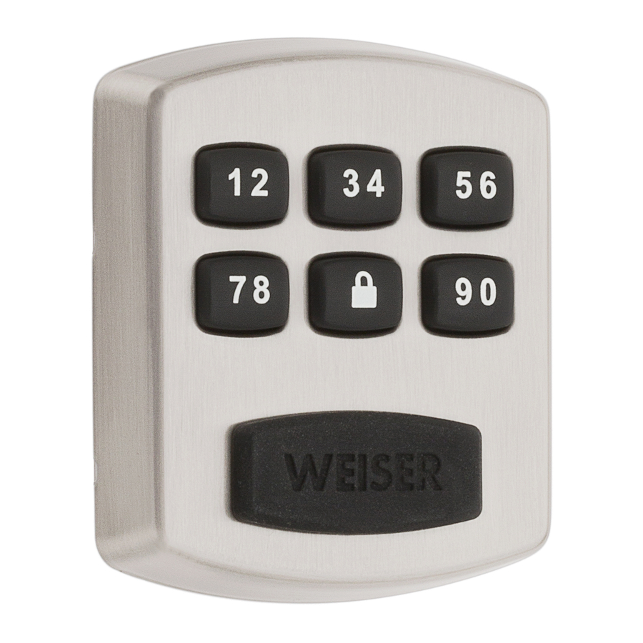
Weiser
Technical Support
1-800-501-9471
www.weiserlock.com
Measure to confirm that the backset is
B
either 2-3/8" or 2-3/4" (60 or 70 mm).
b a
2-3/8" or 2-3/4"
c k
60 or 70 mm
B
Is the door edge chiseled?
Yes
Install latch in door
with supplied screws.
If needed, change
latch plate
NO
A
slotted hole is
NOT centered
180°
Make sure
slotted hole is at
bottom of latch.
A
Parts in the box
Latch
A
A2
Mounting Plate
E
Latch and
Strike Screws
H
Measure to confirm that the hole in
C
the door edge is 1" (25 mm).
s e
t
NO
or
not
chiseled
chiseled
Use a flathead screwdriver to
lift tabs on collar of rectangular
face to remove it from latch.
Install drive-in collar.
A
Align tabs with
A2
holes in collar.
Ensure collar
snaps into place.
Pull collar to
test for tight fit.
A
Install latch
in door
with wood
block and
hammer.
Make sure
slotted hole
is at bottom
of latch.
H (x2)
1 / 4
Strike
C
B
Interior
Assembly
F
Interior Assembly
Mounting Plate Screws
Screws
For 1-3/4"
K
thick doors
J
For 1-3/8"
L
thick doors
Measure to confirm that the
D
door is either 1-3/8" or 1-3/4"
(35 mm or 44 mm) thick.
1"
25 mm
C
Install strike on the door frame.
Make sure hole in door frame is drilled a
minimum of 1" (25 mm) deep.
Make sure the latch bolt is fully retracted
D
B
(in the unlocked position).
Exterior Assembly
D
Interior Cover
G
Tailpiece
M
1-3/8" or 1-3/4"
35 mm or 44 mm
C
H (x2)
door frame
unlocked
Advertisement

Subscribe to Our Youtube Channel
Related Manuals for Weiser Powerbolt 1


Summary of Contents for Weiser Powerbolt 1
- Page 1 Mounting Plate Interior Interior Cover Assembly Installation and User Guide Required tools Latch and Interior Assembly Mounting Plate Screws Tailpiece Weiser Strike Screws Screws Technical Support 4 AA Batteries Ruler Phillips screwdriver For 1-3/4" 1-800-501-9471 thick doors Outils additionnels (en fonction de l’application) www.weiserlock.com...
- Page 2 Install exterior assembly Route the cable below the latch. IMPORTANT: Hold the exterior assembly on the outside firmly (or have a second pair of hands) for the next steps. exterior side of door Route cable beneath the latch Push the cable through the bottom hole. Secure the mounting plate with the supplied screws.
- Page 3 Set Locking and Unlocking Direction What is the location of the latch? Left-Locking Latch Right-Locking Latch If bolt goes left If bolt goes right exterior side of door exterior side of door Press and release PROG. Press and release You will hear 2 long beeps. PROG.
-
Page 4: Troubleshooting
Programming IMPORTANT: Before any programming sequence, make sure that your door is open and unlocked. Note: If the lock is in silent mode, you will not hear the lock beeping. Move swiftly during programming. If no digit is pressed for 10 seconds, the system will time out and you will need to restart the procedure. If setting times out, you will hear 5 short beeps.
Need help?
Do you have a question about the Powerbolt 1 and is the answer not in the manual?
Questions and answers