Table of Contents

Related Manuals for Comtrend Corporation GS-7508


Summary of Contents for Comtrend Corporation GS-7508
- Page 1 Quick Installation Guide GS-7508 | 8-Port PoE Gigabit Ethernet Switch Product Information I-1. Package Contents GS-7508 PoE Switch 4 x Foot Pads Quick Installation Guide Rack-Mount Kit Power Cable...
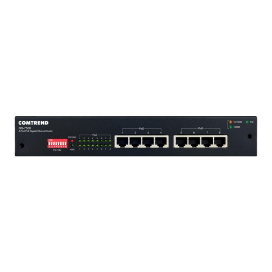
- Page 2 I-2. Hardware Overview Front Panel The front panel of the switch consists of: 8 x 10/100/1000Mbps PoE-Capable RJ-45 Ports Dip Switch Panel PoE Alert LED PWR LED Port LED Indicator Bank Rear Panel The rear panel of the switch consists of: ...
- Page 3 I-3. DIP Switch Definition DIP Switch Status Description This mode makes the PoE Ports 1-2 operate at auto-negotiation 10Mbps speed duplex mode only, but the delivery distance of PoE power and network data (Extend) can reach 200m. This mode makes the PoE Ports Off (Default) 1-2 operate as a general switch.
- Page 4 This mode makes the PoE port 5 Off (Default) operate as a general switch. This mode makes the PoE Port 6 operate at auto-negotiation 10Mbps speed duplex mode only, but the delivery distance of PoE power and network data (Extend) can reach 200m.
- Page 5 PoE Alert: Mode LED Status Description PoE power output over Green the 90% PoE power PoE power output under the 90% PoE power Ethernet Port (Lower Port LED Indicator Bank): Mode LED Status Description 1000Mbps Green On/Blinking connected/data transmitting 10/100Mbps Amber On/Blinking connected/data...
- Page 6 I-6. Rack-Mounting Installation The switch can be mounted in an EIA standard-sized 19-inch rack that can be placed in a wiring closet with other equipment. To install the switch, please follow these steps: 1. Attach the mounting brackets on the switch’s side panels (one on each side) and secure them with the screws provided.
-
Page 7: Quick Setup
Quick Setup II-1. Switch to End Device 1. Connect the switch to local power with the included power cable. 2. Use a standard Cat5/5e Ethernet cable to connect the switch to end devices as shown below. Switch ports will automatically adjust to the link rate of the device to which it’s connected. -
Page 8: Troubleshooting
Your Device is Now Connected! Troubleshooting The following information should help you diagnose basic setup or installation problems. Power LED is OFF: If the Power LED fails to light up, then check if the power cord is properly connected to external power adapter and the power source. -
Page 9: Federal Communication Commission Interference Statement
Federal Communication Commission Interference Statement This equipment has been tested and found to comply with the limits for a Class B digital device, pursuant to part 15 of the FCC Rules. These limits are designed to provide reasonable protection against harmful interference in a residential installation. This equipment generates, uses and can radiate radio frequency energy and, if not installed and used in accordance with the instructions, may cause harmful interference to radio communications. -
Page 10: Supplier's Declaration Of Conformity
Supplier’s Declaration of Conformity Company: Comtrend Corporation - North America Address: 14 Chrysler, Irvine, CA, 92618 Certify and declare under our responsibility that the following equipment: Product Name: 8-Port PoE Gigabit Ethernet Switch Model Name: GS-7508 Brand Name: COMTREND Is tested with the declaration described above, and is in conformity with the relevant FCC (Federal...
Need help?
Do you have a question about the GS-7508 and is the answer not in the manual?
Questions and answers