
Subscribe to Our Youtube Channel
Related Manuals for Comtrend Corporation GS-7526


Summary of Contents for Comtrend Corporation GS-7526
- Page 1 Quick Installation Guide GS-7526 | 26-Port PoE Gigabit Ethernet Switch Product Information I-1. Package Contents GS-7526 PoE Switch Power Cable 4 x Foot Pads Manual CD Rack-Mount Kit...
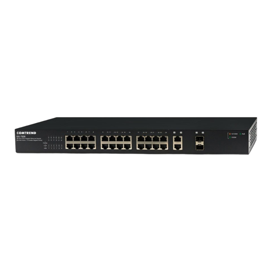
- Page 2 I-2. Hardware Overview Front Panel The front panel of the switch consists of: 24 x 10/100/1000Mbps PoE- Cable RJ-45 Ports 2 x Combo Gigabit Ports Reset Button A Series of LED Indicators Rear Panel The rear panel of the switch consists of: ...
- Page 3 I-3. LED Indicator PWR: LED Status Mode Description Green Power on Power off or fail LOOP: Mode LED Status Description Green Network loop detected No network loop detected PoE/Max: Mode LED Status Description PoE power output over Green 390W PoE power output under 390W Ethernet(above ports): Mode...
- Page 4 SFP: LED Status Mode Description 1000FX connected/data Green On/Blinking transmitting 100FXMbps Amber On/Blinking connected/data transmitting Disconnected or fail PoE (Left of the ports): LED Status Mode Description Green PoE power output on PoE power output off I-4. Desktop Installation Install the switch on a desktop by attaching the cushioning rubber feet to the bottom corners of the switch to protect against external vibration.
- Page 5 I-5. Rack-mounting Installation The switch can be mounted in an EIA standard-sized 19-inch rack that can be placed in a wiring closet with other equipment. To install the switch, please follow these steps: 1. Attach the mounting brackets on the switch’s side panels (one on each side) and secure them with the screws provided.
- Page 6 Quick Setup II-1. Switch to End Device 1. Connect the switch to local power with the included power cable. 2. Use a standard Cat 5/5e Ethernet cable to connect the switch to end devices as shown below. Switch ports will automatically adjust to the link rate of the device to which it’s connected.
Need help?
Do you have a question about the GS-7526 and is the answer not in the manual?
Questions and answers