Omron EJ1N-TC4 Operation Manual
Modular temperature controller
ej1 series
Hide thumbs
Also See for EJ1N-TC4:
- Manual (24 pages) ,
- Quick start manual (3 pages) ,
- User manual (324 pages)
Table of Contents
Advertisement
Quick Links
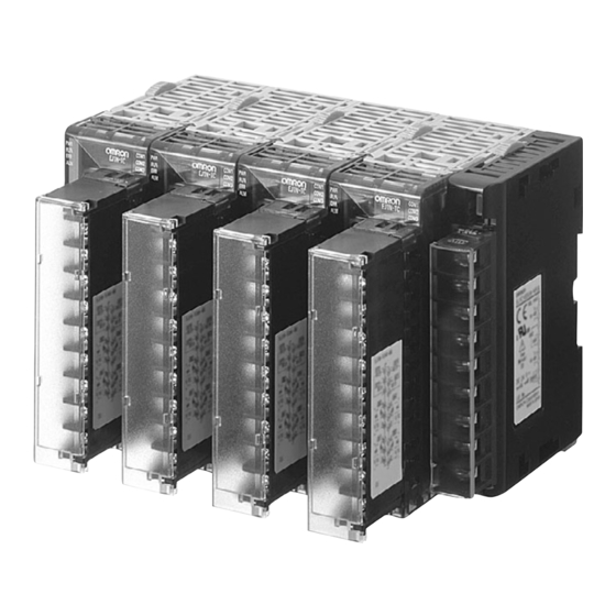
Modular Temperature Controller
EJ1
In-panel Temperature Controller with
Flexible Modular Design for Greater
Integration with Host Devices
• The compact modular structure enables construction of
temperature systems optimally suited to the application.
• Connection can be made to a Programmable Controller without
any programming required, reducing the number of steps
required in ladder programming design.
• One fully multi-input Unit includes a thermocouple, platinum-
resistance thermometer, and analog input for easy selection
and reduced inventory requirements.
• Connect directly to the G3ZA Multi-channel Power Controller
using optimum cycle control for high-accuracy regulation with
minimal noise.
• Improved functionality to enable connecting more devices with
programless communications.
Connect multiple Controllers to one PLC.
Refer to the Safety Precautions on page 21.
Ordering Information
■ Temperature Controller
Standard Control Models
Name
Power
No. of
supply
control
voltage
points
Basic Unit
24 VDC
2
Voltage
(temperature
supplied
output:
control)
from the
2 points (for
(See note 1.)
End Unit
SSR drive)
(See note 2.)
4
2
Current
output:
2 points
HFU
None
None
(See note 1.)
End Unit
24 VDC
(See note 1.)
Note:
1. An End Unit is always required for connection to a Basic Unit or an HFU. An HFU cannot operate without a Basic Unit. External communications cannot be performed when using a
Basic Unit only.
2. For heating/cooling control applications, control outputs 3 and 4 on the 2-point models are used for the cooling or heating control outputs.
On the 4-point models, heating/cooling control is performed for the two input points.
3. When using the heater burnout alarm, purchase a Current Transformer (E54-CT1 or E54-CT3) separately.
4. There are three operation instructions that can be sent to Basic Units connected to an HFU.
Functional Upgrades
Refer to page 17 for details.
Upgrade functions are marked with "V1.1".
Refer to the following manual for precautionary information and other information necessary to use the EJ1:
EJ1 Modular Temperature Controller Operation Manual (Cat. No. H142)
Control
Control
Auxiliary
outputs
outputs
output
1 and 2
3 and 4
Transistor out-
None
put: 2 points
(sinking)
Voltage output:
2 points (for
SSR drive)
(See note 2.)
Transistor out-
put: 2 points
(sinking)
None
Transistor
output:
4 points (sink-
ing)
Transistor
output:
2 points (sink-
ing)
Models with current outputs added.
Functionality improved for Basic Units and HFU
Functions
Communications
functions
Heater
Event
burnout
inputs
alarm
2
2
G3ZA connection
(See note
port: RS-485
3.)
From End Unit:
Port A or port B:
RS-485
None
None
2
4
From End Unit:
(See note
Port A: RS-485
4.)
Port C: RS-485 or
RS-232C
selectable.
From End Unit:
Port A: RS-485
Port C: RS-422
None
Port A or B: RS-485
Connector: Port A
Modular Temperature Controller
Input type
Terminal
Thermocouple,
M3 terminal
EJ1N-TC2A-QNHB
platinum resis-
Screw-less
EJ1N-TC2B-QNHB
tance thermome-
clamp
ter, analog
voltage, and ana-
M3 terminal
EJ1N-TC4A-QQ
log current se-
lectable for each
Screw-less
EJ1N-TC4B-QQ
channel.
clamp
M3 terminal
EJ1N-TC2A-CNB
Screw-less
EJ1N-TC2B-CNB
clamp
No input
M3 terminal
EJ1N-HFUA-NFLK
Screw-less
EJ1N-HFUB-NFLK
clamp
M3 terminal
EJ1N-HFUA-NFL2
Screw-less
EJ1N-HFUB-NFL2
clamp
M3 terminal
EJ1C-EDUA-NFLK
EJ1
Model
1
Advertisement
Table of Contents

Related Manuals for Omron EJ1N-TC4


Summary of Contents for Omron EJ1N-TC4
- Page 1 Modular Temperature Controller In-panel Temperature Controller with Flexible Modular Design for Greater Integration with Host Devices • The compact modular structure enables construction of temperature systems optimally suited to the application. • Connection can be made to a Programmable Controller without any programming required, reducing the number of steps required in ladder programming design.
-
Page 2: Specifications
Mounting Rail PFP-100N PFP-50N Specifications Basic Unit/EJ1N-TC ■ Ratings Item Type EJ1N-TC4 EJ1N-TC2 Power supply voltage 24 VDC Operating voltage range 85% to 110% of rated voltage Power consumption 5 W max. (at maximum load) 4 W max. (at maximum load) Input (See note.) - Page 3 ■ Characteristics Indication accuracy Thermocouple input/platinum resistance thermometer input: (±0.5% of indication value (PV) or ±1°C, whichever is greater) ±1 digit max. (See note 1.) Analog input: ±0.5% FS ±1 digit max. CT input: ±5% FS ±1 digit max. Hysteresis 0.1 to 999.9 EU (in units of 0.1 EU) (See note 2.) Proportional band (P) 0.1 to 999.9 EU (in units of 0.1 EU) (See note 2.)
- Page 4 ■ Communications Specifications Item Port B Port A Terminal/ Port A Connector G3ZA Connection Port (See note 1.) (See note 1.) (See note 2.) Transmission path RS-485 (multipoint) connection Communications RS-485 (two-wire, half duplex) method Synchronization Start-stop synchronization method Communications CompoWay/F, Modbus (See note 4.) CompoWay/F protocol...
- Page 5 ■ Input Ranges Sensor inputs are fully multi-input. Therefore, platinum resistance thermometer, thermocouple, infrared thermosensor, and analog input can be selected. Inputs can be set for each channel using multi-inputs. Input type Platinum resistance thermometer Name Pt100 JPt100 Tem- 2300 pera- 1800 ture...
- Page 6 Communications method RS-485/RS-422 (two-wire, half duplex), RS-232C Synchronization method Start-stop synchronization Communications protocol • OMRON PLC protocol (Connectable PLCs: SYSMAC CS/CJ/CP1H Series) • AnA/AnU CPU common commands (Connectable PLCs: MELSEC-An/AnS/FX Series) V1.1 • MC protocol (form 5) (Connectable PLCs: MELSEC-Q/QnA/QnAS Series) Baud rate 9.6, 19.2, 38.4, 57.6, or 115.2 kbps...
- Page 7 End Unit/EJ1C-EDU ■ Ratings Power supply voltage 24 VDC Operating voltage range 85% to 110% of rated voltage Auxiliary output Outputs (See note.) Transistor outputs Max. operating voltage: 30 VDC, Max. load current: 50 mA Operating: − 10°C to 55°C Ambient temperature range −...
-
Page 8: Unit Configuration Example
Small Systems with 2 Channels or 4 Channels Communicating with the Host Device via RS-485 (CompoWay/F Protocol) • Alarms can be allocated to the auxiliary output for the End Unit. • G3ZA outputs can be used. EJ1N-TC4 EJ1N-TC2 EJ1C-EDU COM1... - Page 9 • In addition to the 2 auxiliary alarm outputs provided on the End Unit, the 4 event inputs/4 auxiliary outputs (transistor outputs) of the HFU can also be used. • G3ZA outputs can be used. • Distributed placement is possible by using multiple EJ1C-EDU End Units RS-232C EJ1N-TC4 EJ1N-HFU EJ1N-TC2 EJ1C-EDU COM1...
- Page 10 • Up to eight HFUs can be connected to one port on a PLC. • To connect more than one HFU, specific PLC and EJ1 models must be used. Refer to Connecting EJ1 Controllers 1:N to a PLC on page 13. SYSMAC (OMRON PLC) RS-485 MELSEC (Mitsubishi Electric PLC) RS-422...
-
Page 11: Node Number Setting
HFU. The End Unit is not included in the 16 Units. One HFU can manage up to 16 Basic Units EJ1C-EDU (when using the EJ1N-TC4: 4 channels x 16 Units = 64 channels) EJ1N-TC4 or EJ1N-TC2 To the host device... - Page 12 Note: Not provided on models with current outputs. Functional isolation ■ Programless Communications Communications with PLCs from OMRON (SYSMAC CS/CJ/CP1H Series) and Mitsubishi Electric (MELSEC-Q/QnA/QnAS/An/Ans/FX Series) can be performed without creating ladder programming. Using programless communications enables monitoring and changing settings for the EJ1 by simply reading and writing to PLC memory.
- Page 13 MELSEC-Q/QnA/QnAS Series Name Model No. Communications ports Channel 1 Channel 2 Q-compatible Serial QJ71C24N RS-232C RS-422/485 Communications Unit QJ71C24 QJ71C24N-R2 RS-232C RS-232C QJ71C24-R2 QJ71C24N-R4 RS-422/485 RS-422/485 QnA-compatible Serial AJ71QC24N RS-232C RS-422/485 Communications Unit AJ71QC24N-R2 RS-232C RS-232C AJ71QC24N-R4 RS-422 RS-422/485 QnAS-compatible Serial A1SJ71QC24N RS-232C RS-422/485...
- Page 14 • Use an SELV power supply. An SELV circuit is one separated from the power supply with double insulation or reinforced insulation, that does exceed an output voltage of 30 V r.m.s. and 42.4 V peak or 60 VDC max. The OMROM S8VS Series is recommended for the power supply. EJ1N-TC4 EJ1N-TC2 OUT2...
-
Page 15: Nomenclature And Specification Settings
■ Internal Wiring Circuit 1 Circuit 3 EJ1N EJ1N EJ1N *Models with Pulse Outputs) -TC2 -HFU -HFU EJ1N EJ1N EJ1N A4/A5 A1/A2 A4/A5 -TC4 -TC2 -TC4 A1/A2 B1/B2 B1/B2 Circuit 2 EJ1N EJ1N EJ1N EJ1C -TC2 -HFU -HFU -EDU A1/A2 B1/B2 B4/B5 Nomenclature and Specification Settings... -
Page 16: Switch Operation
■ Specification Settings Switch Operation SW2 Settings • Check that the EJ1 is turned OFF before operating the switches. EJ1N-TC2/TC4 Settings are read only when power is turned ON. • Set the switches with a small flat-blade screwdriver. Do not set the Meaning switches midway between settings. - Page 17 The following mark is used to indicate descriptions of upgraded functions: V1.1 The functional upgrades are as follows: Basic Units (EJ1N-TC4/2) • Modbus communications can be used on port B. • Software version 2 of G3ZA Multi-channel Power Controller can be used.
-
Page 18: Basic Units
Dimensions Note: All units are in millimeters unless otherwise indicated. ■ Temperature Controller Basic Units 109 (Models with screw terminal blocks) EJ1N-TC 104.85 (Models with screw-less clamp terminal blocks) HFUs COM1 COM1 EJ1N- COM2 EJ1N- COM2 COM3 COM3 EJ1N-HFU 27.0 35.4 95.4 27.6... -
Page 19: End Plate
■ Options Current Transformer (Sold Separately) E54-CT1 5.8 dia. 10.5 Two, 3.5 dia. E54-CT3 2.36 dia. 12 dia. Two, M3 (depth: 4) E54-CT3 Accessory • Armature Connection Example Armature Approx. 3 dia. Plug Lead • Plug Approx. 6 dia. (22) Rail Mounting Equipment (Order Separately) DIN Rail ±0.15... - Page 20 12 to 24 VDC Infrared Thermosensor The number of SSRs that can be connected for each channel is listed Ultra-compact and slim on the right. model combined with a heat radiator EJ1N-TC4 G3PB (Three Phase) COM1 COM1 EJ1-TC2 COM2 EJ1-TC2 COM2...
-
Page 21: Safety Precautions
Safety Precautions 7. Allow as much space as possible between the product and !CAUTION devices that generate a powerful high-frequency or surge. Separate the high-voltage or large-current power lines from other Do not touch the terminals while power is being supplied. lines, and avoid parallel or common wiring with the power lines Doing so may occasionally result in minor injury due to when you are wiring to the terminals. - Page 22 ■ Precautions for Correct Use Wiring Screw-Less Clamp Terminals There are two holes for each terminal. The Installation hole on the right is the operation hole and the hole on the left is the wire hole. 1. Do not connect the End Unit directly to an HFU. Insert a flat-blade screwdriver with a width of 2.
- Page 23 Removing the Terminal Block Dismounting Pull down on the hook with a flat-blade screwdriver and lift up on the 1. Press down the terminal block lever. Unit. Flat-blade Screwdriver Mount one End Plate to each side of the EJ1C-EDU (PFP-M End Lower the lever.
-
Page 24: Terms And Conditions Of Sale
Buyer indemnifies Omron against all related costs or expenses. rights of another party. 10. Force Majeure. Omron shall not be liable for any delay or failure in delivery 16. Property; Confidentiality. Any intellectual property in the Products is the exclu-... - Page 25 Complete “Terms and Conditions of Sale” for product purchase and use are on Omron’s website at www.omron247.com – under the “About Us” tab, in the Legal Matters section. ALL DIMENSIONS SHOWN ARE IN MILLIMETERS. To convert millimeters into inches, multiply by 0.03937. To convert grams into ounces, multiply by 0.03527.
Need help?
Do you have a question about the EJ1N-TC4 and is the answer not in the manual?
Questions and answers