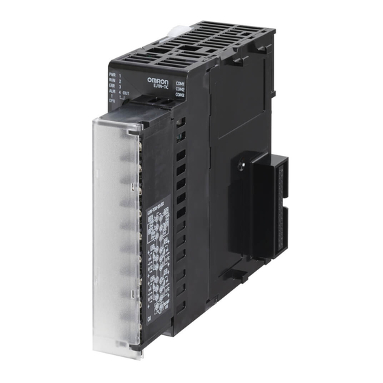
Omron EJ1N-TC2 Series User Manual

Omron EJ1N-TC2 Series User Manual

Modular temperature controllers
Hide thumbs Also See for EJ1N-TC2 Series:
Table of Contents

Advertisement

Quick Links

EJ1
Modular Temperature
Controllers
User's Manual
Cat. No. H142-E1-10

Advertisement

Table of Contents
loading
Need help?

Need help?

Do you have a question about the EJ1N-TC2 Series and is the answer not in the manual?

Questions and answers

Summary of Contents for Omron EJ1N-TC2 Series

  • Page 1 Modular Temperature Controllers User's Manual Cat. No. H142-E1-10...
  • Page 2 No patent liability is assumed with respect to the use of the information contained herein. Moreover, because OMRON is constantly striving to improve its high-quality products, the information contained in this manual is subject to change without notice. Every precaution has been taken in the preparation of this manual. Neverthe- less, OMRON assumes no responsibility for errors or omissions.
  • Page 3 Modular Temperature Controllers User’s Manual Revised December 2024...
  • Page 5 Preface This manual describes the EJ1 Modular Temperature Controllers, including information on functions, performances, and application methods. Observe the following precautions when using an EJ1 Modular Temperature Controller. • Do not allow the Temperature Controller to be handled by anyone except a specialist with sufficient knowledge of electrical systems.
  • Page 6 Products were properly handled, stored, installed and maintained and not subject to contamination, abuse, misuse or inappropriate modification. Return of any Products by Buyer must be approved in writing by Omron before ship- ment. Omron Companies shall not be liable for the suitability or unsuitability or...
  • Page 7 Data presented in Omron Company websites, catalogs and other materials is provided as a guide for the user in determining suitability and does not consti- tute a warranty. It may represent the result of Omron’s test conditions, and the user must correlate it to actual application requirements. Actual performance is subject to the Omron’s Warranty and Limitations of Liability.
  • Page 8 ■ Definition of Precautionary Information The following notation is used in this manual to provide precautions required to ensure safe usage of the product. The safety precautions that are provided are extremely important to safety. Always read and heed the information provided in all safety precautions. The following notation is used.
  • Page 9 ■ Safety Precautions CAUTION Do not touch the terminals while power is being supplied. Doing so may occasionally result in minor injury due to electric shock. Use a power supply that complies with the reinforced insulation specified in IEC 60664 for the EJ1 external power supply or the power supply con- nected to the EJ1.
  • Page 10 CAUTION Always consider the application conditions and use the product within the rated load. If the product is used past its life expectancy, burning may occasionally occur. CAUTION - Risk of Fire and Electric Shock a) This is the product UL Recognition as Open Type Process Control Equipment.
  • Page 11 Conformance to UL/CSA Do not allow temporary overvoltage on the primary circuit to exceed the following values. Check the power supply voltage to the Temperature Controller. Short-term overvoltage: 1,200 V + (Power supply voltage) Long-term overvoltage: 250 V + (Power supply voltage) The power supply terminals must be supplied from a SELV, limited-current source.
  • Page 12 Precautions for Safe Use The product is designed for indoor use only. Do not use the product outdoors or in any of the following locations. • Places directly subject to heat radiated from heating equipment. • Places subject to splashing liquid or oil atmosphere. •...
  • Page 13 15) The switch or circuit breaker must be within easy reach of the operator, and must be marked as a discon- necting means for this unit. 16) Do not use paint thinner or similar chemical to clean with. Use standard grade alcohol. 17) Design the system (e.g., the control panel) allowing leeway for the delay required before product outputs are valid after turning ON power to the product.
  • Page 14 Precautions for Correct Use ● Installation Do not connect an End Unit directly to an HFU. Always connect an End Unit to the right side of the Basic Units. Always connect the HFU to the left side of the Basic Units. You cannot use an EJ1 Controller as a CJ-series Unit.
  • Page 15 Preparations for Use Be sure to thoroughly read and understand the manual provided with the product, and check the fol- lowing points. Timing Check point Details Purchasing the product Product appearance After purchase, check that the product and packaging are not dented or otherwise damaged.
  • Page 16 Related Manuals The manuals related to the EJ1 are configured as shown in the following tables. Refer to these manu- als as required. ■ EJ1 Name Cat. No. Contents H142 Describes the following information on the EJ1. EJ1N-TC2 (This • Overview and features EJ1N-TC4...
  • Page 17 Describes the use of Serial Communications Unit CS1W-SCB1-V1, CS1W-SCU1-V1, CJ1W-SCU1-V1, and Boards to perform serial communications with CJ1W-SCU2 external devices, including the usage of standard Serial Communications Boards/Units Operation Manual system protocols for OMRON products. ■ CP-series PLC Manuals Name Cat. No. Contents CP1H-X40D-...
  • Page 18 Name Cat. No. Contents CP1L-L10D- W462 Provides the following information on the CP CP1L-L14D- Series: CP1L-L20D- • Overview, design, installation, maintenance, and CP1L-M30D- other basic specifications CP1L-M40D- • Features CP1L-M60D- • System configuration SYSMAC CP Series CP1L CPU Unit Operation Manual •...
  • Page 19 ■ Support Software Manuals Name Cat. No. Contents SYSMAC-SE2 W504 Describes the operating procedures of the Sys- Sysmac Studio Version 1 Operation Manual mac Studio. CXONE-ALD-V4/LT-V4 W463 Installation and overview of CX-One FA Integrated SYSMAC CX-ONE FA Integrated Tool Package Setup Man- Tool Package.
  • Page 20 Conventions Used in This Manual Meanings of Abbreviations The following abbreviations are used in parameter names, figures and in text explanations. These abbreviations mean the following: Symbol Term TC4/TC2 Four-channel and Two-channel Basic Units Channel Advanced Unit End Unit Process value Set point Remote SP Local SP...
  • Page 21: Table Of Contents

    TABLE OF CONTENTS SECTION 1 Outline ......... . . Names of Parts.
  • Page 22 TABLE OF CONTENTS SECTION 7 Modbus Communications ......199 Communications Settings ........... Frames .
  • Page 23 About this Manual: This manual describes the EJ1 Modular Temperature Controllers and includes the sections described below. Please read this manual carefully and be sure you understand the information provided before attempting to set up or operate an EJ1 Modular Temperature Controller. •...
  • Page 24 Performance Specifications Upgrades V2.0 EJ1 improves characteristics in version 2.0. The specifications for the Basic Unit (TC4/TC2) and End Unit (EDU) have changed for the following versions: Unit name Models Details Basic Unit EJ1N-TC2A-CNB Two-channel Temperature Controller Standard Control, Screw Terminal Block, Current Output ×...
  • Page 25 • Characteristics Item Previous models ( V1.2/V1.1/V1.0 V2.0 Indication Thermocouple input (±0.5% of indication value or ±1°C, (±0.3% of indication value or ±1°C, accuracy whichever is greater) ±1 digit max. whichever is greater) ±1 digit max. Platinum resistance (±0.5% of indication value or ±1°C, (±0.2% of indication value or ±0.8°C, thermometer input whichever is greater) ±1 digit max.
  • Page 26 Functional Upgrades V1.2 The EJ1C-EDUC-NFLK (with connector terminal block) has been added to the End Units (EDU) and the functions of previous models have been improved. Information in this manual related to improved functionality is indicated with the mark. The improved functionality is outlined below. V1.2 •...
  • Page 27 • Identifying Upgraded Models The new functionality can be used with version 1.2 (V1.2). Check the label on the Temperature Con- troller or the box to determine the version. Models not marked “Ver. 1.1” are version 1.0. Temperature Controller Label Box Label Version Version...
  • Page 28 Functional Upgrades V1.1 EJ1 Temperature Controllers with linear outputs (EJ1N-TC2A-CNB and EJ1N-TC2B-CNB) have been added and the functions of the previous EJ1 Controllers with pulse outputs have been improved. Infor- V1.1 mation in this manual related to improved functionality is indicated with this mark: .
  • Page 29: Outline

    SECTION 1 Outline This section describes the features, nomenclature, and functions of the EJ1. Names of Parts ..........1-1-1 Appearance .
  • Page 30: Names Of Parts

    Names of Parts Section 1-1 Names of Parts 1-1-1 Appearance Slider Front panel Terminal block TC4, TC2, or HFU TC4, TC2, or HFU EDUA EDUC Screw Terminals Screw-Less Clamp Terminals Models with Screw Connector terminal Terminals block model 1-1-2 Names of Parts on Front Panel Operation Indicators Port A connector Operation Indicators...
  • Page 31: Meanings Of Indicators

    Section 1-1 Names of Parts 1-1-3 Meanings of Indicators Operation Indicators TC4 and TC2 Name Color Meaning: When SW2 No. 6 is OFF Meaning: When SW2 No. 6 is ON V1.2 PWR/1 Green Lights when the power is ON. Lit when output 1 is ON. V1.2 RUN/2 Green...
  • Page 32 Names of Parts Section 1-1 Setting Switch 2 (SW2) Settings EJ1-TC Basic Units SW2 (See Meaning note 1.) Set to ON when using the Modbus communications protocol for port B. V1.2 OFF: The setting of the Port B Communications Protocol parameter is used (default: CompoWay/F).
  • Page 33 Section 1-1 Names of Parts EJ1-HFU (Advanced Unit) Meaning 3 to 7 Not used (OFF) • EJ1-HFU-NFLK OFF: RS-485 is selected. ON: RS-232C is selected. • EJ1-HFU-NFL2 Not used (OFF).
  • Page 34: I/O Configuration And Main Functions

    Section 1-2 I/O Configuration and Main Functions I/O Configuration and Main Functions 1-2-1 I/O Configuration TC4: Four-channel Basic Unit Main input 1 Control output 1 Control section Main input 2 Control output 2 Main input 3 Control output 3 Main input 4 Control output 4 G3ZA communications Port A communications...
  • Page 35: Main Unit Functions

    I/O Configuration and Main Functions Section 1-2 EDU: End Unit Port A communications Adjacent Unit Port B communications Auxiliary output 1 (See note.) Auxiliary output 2 (See note.) Note Auxiliary outputs are output via an internal bus. 1-2-2 Main Unit Functions Basic Units (TC4 and •...
  • Page 36: Model Number Legend

    Section 1-2 I/O Configuration and Main Functions • OMRON CS/CJ/NJ-series PLCs and Mitsubishi Q/QnA/QnAS/An/AnS/ FX3UC-series PLCs can be connected. (Version or higher must be V1.1 used for An/AnS/FX3UC-series PLCs. End Unit (EDU) • The End Unit supplies power to connected Basic Units and HFUs.
  • Page 37 Section 1-2 I/O Configuration and Main Functions Communications CompoWay/F (RS-485/RS-232C) CompoWay/F (RS-422) Outputs 4 transistor outputs Terminal Screw terminals type Screw-less clamp terminals Unit name Advanced Unit Type Standard control 9 10 11 12 13 14 H F U A H F U A H F U B N F L K...
  • Page 38: Internal Block Diagrams

    Section 1-3 Internal Block Diagrams Internal Block Diagrams Switch Nonvolatile Indicators inputs memory Waveform Temperature/an- Drive Pulse voltage Main input 1 shaping Control output 1 alog input circuit circuit outputs circuit Waveform Drive Temperature/an- Pulse voltage Main input 2 Control output 2 shaping circuit alog input circuit...
  • Page 39 Internal Block Diagrams Section 1-3 TC2 (V1.2 or lower) Switch Nonvolatile Indicators inputs memory Waveform Temperature/an- Drive Pulse voltage shaping Control output 1 Main input 1 alog input circuit circuit outputs circuit (See note.2) Waveform Temperature/an- Main input 2 shaping alog input circuit circuit Drive...
  • Page 40 Internal Block Diagrams Section 1-3 Switch Nonvolatile Indicators inputs memory Waveform Transistor Event input Drive shaping Auxiliary output 1 Event input 1 outputs circuit circuit circuit Waveform Drive Event input Transistor Auxiliary output 2 Event input 2 shaping circuit outputs circuit circuit Waveform...
  • Page 41: Preparations

    SECTION 2 Preparations This section describes the preparations required to use the EJ1, including installation, wiring, and switch settings. Installation........... . 2-1-1 Dimensions (Unit: mm) .
  • Page 42: Installation

    Installation Section 2-1 Installation 2-1-1 Dimensions (Unit: mm) TC4, TC2, and HFU Models with Screw Terminals: 109 Models with Screw-less Clamp Terminals: 104.85 Models with Screw Models with Screw-less Clamp Terminals Terminals Models with Screw Terminals: 76.2 Connector terminal block model: 79.7 15.7 15.7 EDUA...
  • Page 43: Mounting And Removing Terminal Blocks

    Section 2-1 Installation 2-1-2 Mounting and Removing Terminal Blocks Connecting Units 1,2,3... 1. Align the connectors and connect the Units to each other. Note Connect the EDU on the right end of the EJ1 and the HFU on the left end. 2.
  • Page 44 Section 2-1 Installation Mounting to DIN Rail • Mount the EJ1 to DIN Rail. • Use screws to secure the DIN Rail in at least 3 locations. DIN Rail: PFP-50N (50 cm) or PFP-100N (100 cm) • Install the DIN Rail vertically to the ground. Horizontal: NG Vertical: OK Installation Method...
  • Page 45 Installation Section 2-1 End Plate Installation Always mount an End Plate on each side of the EJ1. PFP-M End Plates (2) PFP-M Removing Terminal Blocks 1,2,3... 1. Pull down the terminal block lever. Pull down the lever. 2. Pull off the terminal block. Pull off the terminal block.
  • Page 46: Wiring Terminals

    Section 2-2 Wiring Terminals Wiring Terminals 2-2-1 Terminal Arrangement To comply with EMC standards, the cable that connects the sensor must be 30 m or less. If the cable length exceeds 30 m, it will not be possible to comply with EMC standards.
  • Page 47 Section 2-2 Wiring Terminals Linear output Pulse output Transistor output OUT2 OUT2 Max. operating voltage: 30 VDC 12 VDC, 21 mA Max. load current: 100 mA 4 to 20 mA DC or 0 to 20 mA DC OUT1 OUT1 OUT4 4 to 20 mA DC or 12 VDC, 21 mA 0 to 20 mA DC...
  • Page 48: Wiring Precautions

    Section 2-2 Wiring Terminals Port A connector Port A connector Port A on Port A on These two ports These two ports B (+) B (+) terminal block terminal block cannot be used at cannot be used at the same time. the same time.
  • Page 49: Wiring

    Wiring Terminals Section 2-2 • Use the following types of crimp terminals for M3 screws. 5.8 mm max. 5.8 mm max. Wiring Procedure for There are two holes for each terminal. The hole on the right is the operating Screw-Less Clamp hole;...
  • Page 50 Note Select a power supply that suits the operating environment. • To meet EN61326 Class A noise terminal voltage standards, insert a noise filter (Omron S8V-NF series or equivalent*) into the DC line as close as possible to the EJ1.
  • Page 51 Section 2-2 Wiring Terminals Control Outputs Terminals B1 to B3 and A1 to A3 on the TC4/TC2 are for control outputs. OUT2 12 VDC, 21 mA 12 VDC, 21 mA OUT4 OUT1 OUT3 12 VDC, 21 mA 12 VDC, 21 mA −...
  • Page 52 Wiring Terminals Section 2-2 If you use self-tuning (ST), additional precautions are required. Refer to page 85. Auxiliary Outputs Auxiliary outputs are sent from pins B1 to B6 with the HFU, and from pins 3 to 5 with the EDUA. When using an EDUC, auxiliary outputs are sent from pins 3 to 6.
  • Page 53 Section 2-2 Wiring Terminals • Use the CT for the following models. Version UL certification required UL certification not required V2.0 or higher E54-CT1L, E54-CT3L E54-CT1L, E54-CT3L, E54-CT1 and E54-CT3 V1.2 or lower E54-CT1, E54-CT3 E54-CT1L, E54-CT3L, E54-CT1 and E54-CT3 Event Inputs Connect event inputs across terminals A4 and A6 for the TC2 and terminals A1 and A6 for the HFU.
  • Page 54 Section 2-2 Wiring Terminals Communications • For communications with the host, connect communications across termi- nals B7 and B8 or terminals A7 to A9 on the HFU or connect across ter- minals 1 and 2 or terminals 6 and 7 on the EDU. When using a connector terminal block model, connect communications across terminals 7 and 8.
  • Page 55 Wiring Terminals Section 2-2 • The RS-485 connection can be either 1: 1 or 1: N. RS-232C connections can only be 1: 1. A maximum of 64 Units (including the host) can be con- nected in 1: N systems. The maximum total cable length is 500 m. Use AWG28 (cross-sectional area: 0.081 mm ) to AWG16 (cross-sectional area: 1.309 mm...
  • Page 56 B (+) Crimp Terminals A (−) Model: SPHD-001T-P0.5 Use an EJ1-CBLA050 Cable (manufactured by OMRON). The EJ1 contains 120 Ω of terminating resistance. Connect a terminating resistor (110 to 125 Ω, 1/2 W) only to the end G3ZA node. TC4/TC2...
  • Page 57: Using Tool Ports

    Section 2-3 Using Tool Ports Using Tool Ports Tool ports are used to make EJ1 settings using the EST2-2C-MV CX- Thermo Support Software. The E58-CIFQ1 USB-Serial Conversion Cable is required to make the con- nection. 2-3-1 Procedure 1,2,3... 1. Turn ON the power to the EJ1. Note Do not connect the E58-CIFQ1 when power to the EJ1 is OFF.
  • Page 58: Unit Configuration Examples

    Section 2-4 Unit Configuration Examples Unit Configuration Examples Minimal Configuration • The two auxiliary alarm outputs (transistor outputs) provided on the End Unit can be used. • The G3ZA or G3PW can be connected. EJ1@-TC4 EJ1@-EDU EJ1@-TC2 Port A (connector): USB connection can be made using the E58-CIFQ1 (sold separately).
  • Page 59 Section 2-4 Unit Configuration Examples Multiple Units with an HFU • The two auxiliary alarm outputs (transistor outputs) provided on the End Unit can be used. • In addition to the two auxiliary alarm outputs provided on the End Unit, the four event inputs and four transistor outputs on the HFU can be used.
  • Page 60: Connection Precautions

    Section 2-4 Unit Configuration Examples 2-4-1 Connection Precautions Restrictions on the Number of Units that Can Be Connected • You can set communications unit numbers 0 to 7 for the HFU (or 32 to 39 for version V1.2 • You can set communications unit numbers 0 to 63 for the TC4/TC2 (or 0 to 31 if the HFU is connected).
  • Page 61 Section 2-4 Unit Configuration Examples One HFU can manage up to 32 TC Units (4 channels × 32 Units = 128 channels) EDU Units are not included in the number of Units that can be managed. Turn ON pin 8 on SW2.
  • Page 62 Section 2-4 Unit Configuration Examples • You must connect the communications cable between the port A terminal blocks on TC4/TC2 Units that are connected with distributed placement to set up the TC4/TC2 Units from the CX-Thermo Support Software running on a computer. EJ1@-TC4 or EJ1@-TC2 EJ1@-EDU Up to 64 Basic Units can be connected...
  • Page 63 Section 2-4 Unit Configuration Examples tributed placement to set up the TC4/TC2 Units from the CX-Thermo Sup- port Software on a computer. (2)Use this wiring when an HFU Unit is not used. Connecting the G3ZA or • Up to 8 G3ZA Multi-channel Power Controllers or G3PW Power Control- G3PW to the EJ1 lers can be connected to one TC4/TC2 Unit.
  • Page 64 Section 2-4 Unit Configuration Examples...
  • Page 65: Typical Control Examples

    SECTION 3 Typical Control Examples This section describes the basic applications of the EJ1 using specific control examples. Minimum Configuration for Control ....... 3-1-1 Application .
  • Page 66: Minimum Configuration For Control

    Section 3-1 Minimum Configuration for Control Minimum Configuration for Control 3-1-1 Application This section shows an example configuration for a small electric oven and explains how to set up and control the system using the CX-Thermo Support Software. Small electric oven Temperature Sensor Heater...
  • Page 67: Wiring

    Section 3-1 Minimum Configuration for Control 3-1-2 Wiring • Connect the Temperature Sensor to the input terminals according to the sensor's input type. • Connect the Solid State Relay to the output terminals. When an EJ1-TC2 is used, wire the circuits as shown below. EJ1@-TC2 Small electric oven OUT2...
  • Page 68 Section 3-1 Minimum Configuration for Control 4. The following table shows the related parameter settings for this example. CX-Thermo Basic Mode Setting Example Setting example Remarks EJ1N-TC2A-QNHB 0 Control in progress parameters Bank 0 Bank 0 Set Point - CH1 150°C Bank 0 Proportional Band - CH1 8.0°C...
  • Page 69: Adjustment

    Minimum Configuration for Control Section 3-1 3-1-4 Adjustment Execute autotuning (AT) to make the PID adjustments. If self-tuning (ST) is activated, the PID will be automatically calculated when using standard control. V1.2 Refer to 4-3-8 Tuning. When the CX-Thermo Support Software is being used, both EJ1 control and autotuning can be started/stopped using operation commands.
  • Page 70: Multi-Channel Control

    Multi-channel Control Section 3-2 Multi-channel Control 3-2-1 Application In this example configuration, an EJ1 controls a 4-zone heater plate. Programmable Terminal CJ1W-CIF11 RS-422A Converter RS-485 Wafer Temperature Sensor Heater plate Control outputs: Channels 1 to 4 G3PB Sensor inputs: Solid State Relays for Channels 1 to 4 single-phase heaters •...
  • Page 71: Wiring

    Section 3-2 Multi-channel Control 3-2-2 Wiring Connect the Temperature Sensor to the input terminals according to the sen- sor's input type. Connect the Solid State Relays for zones 1, 2, 3, and 4 to output terminals OUT1, OUT2, OUT3, and OUT4, respectively. When an EJ1-TC4 is used, wire the circuits as shown below.
  • Page 72: Adjustment

    Multi-channel Control Section 3-2 Related parameters Description CH3 - Set Point (Variable type D4, Address 0300) 047E: 115. 0°C CH4 - Set Point (Variable type D4, Address 0400) 047E: 115. 0°C CH1 - Control Period 1 (Variable type E1, Address 0101) 0000: 0.5 s CH2 - Control Period 2 (Variable type E1, Address 0201) 0000: 0.5 s...
  • Page 73: Control Linked To A Host Device

    Section 3-3 Control Linked to a Host Device Control Linked to a Host Device 3-3-1 Application In this example configuration, a CJ1-series PLC controls a reflow oven and an EJ1 performs temperature control on 6 zones and 12 control loops in the oven.
  • Page 74: Wiring

    Section 3-3 Control Linked to a Host Device 3-3-2 Wiring Connect the Temperature Sensors to the input terminals according to the sen- sor's input type. • Connect the Solid State Relays to the output terminals. • Connect the PLC with an RS-232C communications cable. Wire the circuits as shown below when using an EJ1-HFU and three EJ1- TC4 Units.
  • Page 75: Setup

    Control Linked to a Host Device Section 3-3 3-3-3 Setup Refer to 3-2 Multi-channel Control for details on the EJ1-TC4 settings. The settings are made through communications. The CX-Thermo Support Software can be connected using an E58-CIFQ1 Connecting Cable to set the parameters from a personal computer.
  • Page 76: Adjustment

    Section 3-3 Control Linked to a Host Device Note • The Programmable Terminal and E58-CIFQ1 Connecting Cable cannot be connected at the same time. • When connecting the cable for the Support Software to an EJ1C-EDU End Unit, either turn OFF the Programmable Terminal's power supply or switch the Programmable Terminal's screen to the system menu.
  • Page 77: Controlling G3Za Controllers Connected To Output Devices

    Section 3-4 Controlling G3ZA Controllers Connected to Output Devices Controlling G3ZA Controllers Connected to Output Devices 3-4-1 Application In this example configuration, G3ZA Multi-channel Power Controllers are used to control the temperature in a 4-zone heater plate with a single control loop by applying a fixed coefficient (slope) to the results of the EJ1's PID calcula- tions.
  • Page 78 Section 3-4 Controlling G3ZA Controllers Connected to Output Devices Using the G3ZA's MV Calculations for Slope (Gradient) Control G3ZA Multi-channel Power Controller Unit MV 11 No.1 MV 12 Channel 1 RS-485 sensor input MV 13 MV 14 RS-485 Unit MV 21 Channel 2 No.2 sensor input...
  • Page 79: Wiring

    Section 3-4 Controlling G3ZA Controllers Connected to Output Devices 3-4-2 Wiring Connect the Temperature Sensors to the input terminals according to the sen- sor's input type. • Connect the EJ1 and G3ZA with the EJ1C-CBLA050 Cable. • Connect the Solid State Relays to the G3ZA's output terminals. When using an EJ1-TC4 and G3ZA-4H203-FLK, wire the circuits as shown in the following diagram.
  • Page 80: Setup

    Section 3-4 Controlling G3ZA Controllers Connected to Output Devices 3-4-3 Setup The settings are made through communications. The CX-Thermo Support Software can be connected using an E58-CIFQ1 Connecting Cable to set the parameters from a personal computer. The following table shows the parameters related to the G3ZA that can be set from the Temperature Controller, as well as example settings.
  • Page 81: Basic Units (Tc4 And Tc2) Functions

    SECTION 4 Basic Units (TC4 and TC2) Functions This section describes the functions of EJ1 Basic Units. Setting Input Specifications ........4-1-1 Input Type.
  • Page 82 Using the Loop Break Alarm (LBA) ....... . 4-6-1 Loop Burnout Alarm (LBA) ....... Other Functions (TC4 and TC2) .
  • Page 83: Setting Input Specifications

    Section 4-1 Setting Input Specifications Setting Input Specifications 4-1-1 Input Type Set the input type to match the type of sensor being used. Variable type Parameter name Setting range Default E0/A0 Input Type (Channel) 0 to 29 0 to 30 V1.2 Conditions for use No special conditions...
  • Page 84: Temperature Inputs

    Section 4-1 Setting Input Specifications 4-1-2 Temperature Inputs ■ Temperature Unit Either °C or °F can be selected. Variable type Parameter name Setting range Default E0/A0 Temperature unit (Channel) 0: °C/1: °F Conditions for use The input type must be set to temperature input. Note This parameter can be set only when operation is stopped.
  • Page 85: Input Shift (Correction)

    Section 4-1 Setting Input Specifications Variable type Parameter name Setting range Default (Channel) −1999 to 9999 E0/A0 Scaling Upper Limit 1000 (See note.) (Channel) −1999 to 9999 Scaling Lower Limit Decimal Point Position (Channel) 0: **** (no decimal point) 1: ***.* 2: **.** 3: *.*** Conditions for use...
  • Page 86 Section 4-1 Setting Input Specifications Simple Shift: One- The temperature measurements at all points in the sensor range are shifted. point Shift For example, make the following settings if you want to increase the tempera- ture by 1.2°C. • Input Shift 1 = Input Shift 2 = 1.2 Note It is not necessary to set the Input Value 1 for Input Correction or Input Value 2 for Input Correction parameters.
  • Page 87 Section 4-1 Setting Input Specifications Two-point Shift Method 1,2,3... 1. Shift the controller readout at two reference temperatures, near room tem- perature and near the value at which the temperature of the control target is to be controlled. Bring the temperature of the control target close to room temperature and close to the set point, and check control target tempera- ture (B) and controller readout (A).
  • Page 88: Input Filter

    Section 4-1 Setting Input Specifications Input Value 2 for Input Correction = Controller readout (A) = 500°C Input Shift 2 = Object temperature (B) - Controller readout (A) = 550°C − 500°C = 50.00°C 4-1-5 Input Filter Sets the time constant of the digital input filter. The following diagram shows the response of the digital filter to a step-wise input of amplitude A.
  • Page 89: Setting Output Specifications

    Section 4-2 Setting Output Specifications Setting Output Specifications 4-2-1 Control Output Assignments The parameters shown in the following diagram can be assigned to each out- put by setting the control output assignments. The same parameter can be assigned to different outputs. OUT1 OUT2 OUT3...
  • Page 90: Control Output Method

    Section 4-2 Setting Output Specifications 4-2-2 Control Output Method The time-proportional output method is used for the control output. The MV determines the percentage of time that the output is ON during each control period. 100% Control period Note Control responsiveness improves as the control period is short- ened, but if relays are being used for heater control, the relay life- time will also be shortened so we recommend using a control period of at least 20 seconds.
  • Page 91: Output On Scheduling Function

    Section 4-2 Setting Output Specifications Variable type Parameter name Setting range Default E1/A1 Minimum output ON/OFF 0.0 to 50.0% width (IO) Conditions for use Control output must be assigned and set to 2-PID control. These parameters are not valid for outputs 1 and 2 on Control- lers with linear outputs.
  • Page 92 Section 4-2 Setting Output Specifications • Even if the Output ON Scheduling Method is set, the outputs may be ON at the same time due to the delay in the output device's operation. In this case, you can prevent the outputs from being ON simultaneously by setting a delay with the Delay between Outputs parameter.
  • Page 93: Output Scaling

    Section 4-2 Setting Output Specifications 2 s = 10 s × 20% OUT1 Delay between Outputs: 1,000 ms = 1 s OUT2 2.5 s = 10 s × 25% OUT3 OUT4 Delay between outputs Control period: 10 s for four channels Note The Delay between Outputs parameter can be set to offset the ON time for each output.
  • Page 94: Transfer Outputs

    Section 4-2 Setting Output Specifications Example: Making All TC4 Outputs into CH1 Control Output (Heating) with Dif- ferent Slopes Actual output Output Parameter name Set value Output 1 Control output 1 assignment CH1 Control out- 100.0% Output 1 put (heating) Output 2 Output Scaling Upper Limit 1 100 Output Scaling Lower Limit 1 0...
  • Page 95 Section 4-2 Setting Output Specifications ■ Example: Differences when Linear Output Type (4 to 20 mA) is used • When used as "Transfer Output (Heating)", 4.0 mA is output for 0%, and 20.0 mA is output for 100%. • When used as "Control Output (Heating)", the manipulated target must be either 0% or 100% with certitude, so 3.7 mA is output for 0%, and 20.3 mA is output for 100%.
  • Page 96 Section 4-2 Setting Output Specifications ■ Example: The following example outputs the process value on a transfer output. Parameter Default Input Type 6 (−20.0 to 500.0°C) Control Output 1 Assignment 43 (channel 1 process value) Linear Output 1 Type 1 (0 to 20 mA) Output Scaling Upper Limit 1 Output Scaling Lower Limit 1 Decimal Point C1...
  • Page 97: Setting Control Specifications

    Section 4-3 Setting Control Specifications Setting Control Specifications 4-3-1 Starting and Stopping Control ■ Start Control (RUN) and Stop Control (STOP) The following two methods can be used to start/stop control. For details, refer to the corresponding pages. (1) Starting/stopping control with an operation command: 6-4-11 Operation Commands (2) Starting/stopping control with an event input: 4-7-2 Event Inputs (TC2) ■...
  • Page 98: Selecting The Control Method

    Section 4-3 Setting Control Specifications 4-3-2 Selecting the Control Method The control method can be set to either 2-PID control or ON/OFF control. Variable type Parameter name Setting range Default E5/A5 PID/OnOff (Channel) 0: 2-PID control 1: ON/OFF control Conditions for use No special conditions Note This parameter can be set only when operation is stopped.
  • Page 99 Setting Control Specifications Section 4-3 ■ Three-position Control In heating/cooling control, a dead band area can be set where the MV is 0% for both heating and cooling. with a dead band, 3-position control can be achieved. Dead band Hysteresis (Heating) Hysteresis (Cooling) Heating side Cooling side...
  • Page 100 Setting Control Specifications Section 4-3 • Derivative action: This control action produces an output that is propor- tional to the rate of change of the input. Since propor- tional control and integral control correct for errors in the control result, the control system will be slow to respond to sudden changes in temperature.
  • Page 101: Selecting The Output Mode

    Section 4-3 Setting Control Specifications ■ Setting the Alpha This parameter sets the 2-PID constant alpha (α). Note Normally, this parameter is left at its default value. Variable type Parameter name Setting range Default D5/95 Alpha (Channel) 0.00 to 1.00 0.65 Conditions for use The control method must be set to 2-PID control.
  • Page 102 Setting Control Specifications Section 4-3 Heating/Cooling To perform heating/cooling control, assign the control output (cooling) function Control to one of the outputs. For example, when you want to perform heating/cooling control with channel 1, assign channel 1 control output (cooling) to one of the outputs.
  • Page 103 Section 4-3 Setting Control Specifications Variable type Parameter name Setting range Default (BANK) −199.9 to 999.9 EU D0/90 Dead Band Conditions for use The control method must be set to heating/cooling control. Note The decimal point position is determined by the sensor selection. In this case, however, the 0 (****) decimal point position setting will be treated as setting 1 (***.*).
  • Page 104: Setting The Set Point

    Section 4-3 Setting Control Specifications Water cooling cooling Linear MV % (cooling) Note When using a relay for cooling output, the minimum output ON/OFF width can be used to prevent relay degradation. For details on this setting, refer to page 62. 4-3-4 Setting the Set Point These parameters set the set point.
  • Page 105: Setting The Sp Ramp

    Setting Control Specifications Section 4-3 Input range SP Limiter range Internal SP When the input type is changed, the input range is narrowed. Input range SP Limiter range Internal SP Note The SP is not changed, but the internal SP used for control is lim- ited by the upper limit of the input range.
  • Page 106: Remote Sp

    Section 4-3 Setting Control Specifications Variable type Parameter name Setting/monitoring Default range E5/A5 (See note 1.) SP Ramp Time Unit 0: Seconds (Channel) 1: Minutes D0/90 SP Ramp Rise Value 0 to 9999 EU/s or min (BANK) (See note 2.) SP Ramp Fall Value 0 to 9999 EU/s or min (BANK)
  • Page 107 Section 4-3 Setting Control Specifications TC2: CH1 TC2: CH2 Channel 3: Remote SP of channel 1 TC4: CH1/CH2 TC4: CH3/CH4 Channel 4: Remote SP of channel 2 Selected bank's Process value Process value If remote SP mode is enabled, the process value operates as the remote SP input.
  • Page 108 Section 4-3 Setting Control Specifications Remote SP range Input range SP Limiter range Internal SP If the remote SP exceeds the upper If the remote SP exceeds the SP limit of the input range, the internal Lower Limit, the internal SP is SP is limited to the sensor's upper limited to the SP Lower Limit.
  • Page 109: Setting The Manipulated Variable (Mv)

    Section 4-3 Setting Control Specifications Variable type Parameter name Setting range Default E5/A5 (See note.) SP Tracking (Channel) 0: Disabled 1: Enabled Conditions for use The Remote SP function must be enabled. Note This parameter can be set only when operation is stopped. SP tracking can be used for channel 1 or channel 2 for the TC4, but only for channel 1 for the TC2.
  • Page 110 Section 4-3 Setting Control Specifications ■ MV at Stop This parameter sets the MV when control is stopped. For heating/cooling control, the MV at Stop parameter applies to the cooling side if the MV is negative and to the heating side if the MV is positive. The default is 0.0, so an MV will not be output for either standard or heating/ cooling control with the default setting.
  • Page 111: Tuning

    Section 4-3 Setting Control Specifications Output Cooling Heating MV Lower Limit MV Upper Limit Output Mode Selection = Heating/cooling control Variable type Parameter name Setting range Default MV Upper Limit (Channel) −5.0 to 105.0 (for standard control) D5/95 105.0 0.0 to 105.0 (for heating/cooling control) % −105.0 MV Lower Limit (Channel) −5.0 to 105.0 (for standard control) −105.0 to 0.0 (for heating/cooling control) %...
  • Page 112 Section 4-3 Setting Control Specifications (2) The decimal point position is determined by the sensor selection. In this case, however, the 0 (****) decimal point position setting will be treated as setting 1 (***.*). ■ AT Calculated Gain Sets the gain used when calculating the PID constants in autotuning. When emphasizing flexibility, decrease set value.
  • Page 113 Section 4-3 Setting Control Specifications Process Limit Cycle value MV Amplitude 100% Set point Time Autotuning starts Autotuning completed V1.2 Self-tuning (ST) Self-tuning (ST) finds the PID constants by using step response tuning (SRT) when the EJ1 is operated or the set point is changed. Once the PID constants have been calculated, ST does not execute when the next control operation is started as long as the set point remains unchanged.
  • Page 114 Section 4-3 Setting Control Specifications Starting Conditions Self-tuning by step response tuning (SRT) is started at the start of operation and when the set point is changed when the following conditions are met. At start of operation When the set point is changed 1.
  • Page 115 Section 4-3 Setting Control Specifications • When using this function, set the following parameters to their default set- tings: Output Scaling Upper Limit 1 to 4, Output Scaling Lower Limit 1 to 4, and Decimal Point C1 to C4. If these parameters are set to anything other than their defaults, ST will not operate properly.
  • Page 116: Disturbance Overshoot Adjustment Function

    Section 4-3 Setting Control Specifications Conditions for use The control method must be set to 2-PID control and the input type must be a temperature input. Note This parameter can be set only when operation is stopped. 4-3-9 Disturbance Overshoot Adjustment Function The Disturbance Overshoot Adjustment Function adjusts the control wave- form when an external disturbance impacts the system.
  • Page 117: 4-3-10 Operation During Errors

    Section 4-3 Setting Control Specifications Temperature Disturbance Time Constant = 1 Disturbance Time Constant = 2 Time Note The waveform shown in the diagram above will vary depending on the control object's characteristics and the PID constant settings. Starting Conditions The Disturbance Overshoot Adjustment Function will operate after the pro- for the Disturbance cess value (PV) has stabilized in the Disturbance Rectification Band and the...
  • Page 118 Section 4-3 Setting Control Specifications the next time a software reset is performed for the Unit or the next time power is turned ON. • When setting 1 (MV at PV Error) is being used, set the MV at PV Error in variable type D5/95.
  • Page 119: Setting Alarm Specifications

    Section 4-4 Setting Alarm Specifications Setting Alarm Specifications 4-4-1 Alarm Types Set the alarm type for each of the alarms in Alarm 1 Type, Alarm 2 Type, and Alarm 3 Type (variable type: E3/A3). Set value Alarm type Alarm Output Function When alarm value X is positive When alarm value X is negative Alarm function OFF Output OFF...
  • Page 120: Alarm Value

    Section 4-4 Setting Alarm Specifications (4) Set value: 5, Upper and lower-limit with standby sequence Note For the above upper and lower-limit alarm: • In cases 1 and 2 above, the alarm is always OFF if the hystere- sis overlaps the upper and lower limits. •...
  • Page 121: Standby Sequence

    Section 4-4 Setting Alarm Specifications 4-4-4 Standby Sequence The standby sequence can be used so that an alarm will not be output until the process value leaves the alarm range once and then enters it again. For example, with a lower limit alarm, the process value will normally be below the set point, i.e., within the alarm range, when the power supply is turned ON, causing an alarm to be output.
  • Page 122: Closed In Alarm Or Open In Alarm

    Section 4-4 Setting Alarm Specifications 4-4-6 Closed in Alarm or Open in Alarm When Close in Alarm is set, the alarm output function's status will be output as-is. When Open in Alarm is set, the alarm output function's status will be reversed before being output.
  • Page 123: Alarm Sp Selection

    Section 4-4 Setting Alarm Specifications • The alarm will not turn ON if the time that the alarm is ON is equal to or less than the ON delay set time. Likewise, the alarm will not turn OFF if the time that the alarm is OFF is equal to or less than the OFF delay set time.
  • Page 124: Detecting Current Errors

    Section 4-5 Detecting Current Errors Detecting Current Errors 4-5-1 CT Assignment (TC2) This parameter specifies which output's current is being measured. Three-phase heater burnout detection can also be performed by assigning two CTs to one output. Variable type Parameter name Setting range Default E4/A4...
  • Page 125 Section 4-5 Detecting Current Errors Note (1) In the above diagram, power is considered to be ON (normal) if the heater current is greater than the heater burnout detection current during the ON time. If the heater is burned out, the current measured at the current transformer decreases.
  • Page 126 Section 4-5 Detecting Current Errors Installing Current Connect the CT in advance to terminals A8 and A9 (CT1) or A7 and A9 (CT2), Transformers (CT) and pass the heater power line through the CT's hole. Refer to Current Trans- former on page 243 for details on compatible CT specifications, models, and (HB Alarm) dimensions.
  • Page 127 Section 4-5 Detecting Current Errors To CT input Load: Heater (example) AC line To CT input Calculating the Heater Calculate the set value with the following equation: Burnout Detection Normal current value + Burnout current value Set value = Current Value •...
  • Page 128 Section 4-5 Detecting Current Errors ■ Examples 1. Single-phase Heaters Example 1 Using a 200-VAC, 1-kW Heater Normal operation Heater burnout occurred AC line AC line 200 V Load 200 V Load Burnout To CT input To CT input The heater current is 5 A when the current is normal, and 0 A when there is a burnout, so the heater burnout detection current is calculated as follows: Normal current value + Burnout current value ∴...
  • Page 129 Section 4-5 Detecting Current Errors 2. Three-phase Heaters a. Delta Connection Example: Using Three 200-VAC, 2-kW Heaters Normal Operation 17.3 A Load: Heater (example) 200 V 200 V 17.3 A Load 200 V To CT input 17.3 A To CT input When each phase's current is normal, the current is: ×...
  • Page 130 Section 4-5 Detecting Current Errors b. Star Connection Example: Using Three 200-VAC, 2-kW Heaters Normal Operation 5.8 A Load: Heater (example) 200 V 200 V 5.8 A 200 V To CT input 5.8 A To CT input   When each phase's current is normal, the current is: 5.8 A ≅ 10 A × ------ - ...
  • Page 131: Heater Short Alarm (Hs Alarm)

    Section 4-5 Detecting Current Errors c. V Connection Example: Using Two 200-VAC, 2-kW Heaters Normal Operation 10 A 200 V To CT input Load: Heater (example) 200 V 17.3 A 200 V 10 A To CT input Heater Burnout Occurred 10 A 200 V 200 V...
  • Page 132 Section 4-5 Detecting Current Errors OFF time (See note 2.) ON time Control output (heating) Note (1) In the above diagram, power is considered to be OFF (normal) if the leak- age current is less than the HS alarm current during the OFF time. If the SSR output is short-circuited, the measured current will increase beyond the HS alarm value and an HS Alarm will be output.
  • Page 133: Heater Overcurrent Alarm (Oc Alarm)

    Section 4-5 Detecting Current Errors ■ HS Alarm Latch and Latch Cancel The HS alarm latch can be used to keep an HS alarm ON once it goes ON. The latch can be released by executing an operation command (Reset Error or Software Reset), cycling the power, or setting the HS Alarm parameter to 100.0 A.
  • Page 134 Section 4-5 Detecting Current Errors (3) The OC Alarm can be forced ON or OFF, regardless of the actual heater current value, by setting the OC (Heater Overcurrent) Alarm parameter to 0.0 or 100.0. Use the 0.0 and 100.0 settings to check operation. (4) This parameter can be set only when operation is stopped.
  • Page 135: Using The Loop Break Alarm (Lba)

    Section 4-6 Using the Loop Break Alarm (LBA) Using the Loop Break Alarm (LBA) 4-6-1 Loop Burnout Alarm (LBA) With a loop burnout alarm, there is assumed to be an error in the control loop if the control deviation (SP-PV) is greater than the threshold set in the LBA Level parameter and if the control deviation is not reduced by at least the value set in the LBA Band parameter within the specified LBA Detection Time.
  • Page 136 Section 4-6 Using the Loop Break Alarm (LBA) Determining the LBA • Automatic Settings Detection Time The LBA detection time is set automatically by autotuning. (It is not set automatically for heating/cooling control.) If the optimum LBA detection time is not obtained by autotuning, set the LBA Detection Time parameter.
  • Page 137: Other Functions (Tc4 And Tc2)

    Section 4-7 Other Functions (TC4 and TC2) Other Functions (TC4 and TC2) 4-7-1 Bank Function Up to 4 banks can be created with the following parameters registered inde- pendently. • Set point • Proportional Band • Integral Time • Derivative Time •...
  • Page 138: Event Inputs (Tc2)

    Section 4-7 Other Functions (TC4 and TC2) 4-7-2 Event Inputs (TC2) Event Input There are two event inputs in the TC2. Assignment The following diagram shows the parameters that can be set in event input 1 or event input 2. Some of the parameters are for all channels and others are for individual channels.
  • Page 139: Internal Buses (Tc4 And Tc2)

    Other Functions (TC4 and TC2) Section 4-7 ■ Stop (0)/Run (1), Run (0)/Stop (1), Auto (0)/Manual (1), Local SP (0)/ Remote SP (1) Parameter Event input Description Stop (0)/Run (1) Stop Run (0)/Stop (1) Stop Auto (0)/Manual (1) Auto Manual Local SP (0)/Remote SP (1) (See note.) Local SP Remote SP...
  • Page 140 Other Functions (TC4 and TC2) Section 4-7 Bus I/O Assignments The following diagrams show the parameters that can be set in the Bus Input 1 to 3 Assignment and Bus Output 1 to 3 Assignment parameters. Refer to the Example on page 113, when setting parameters. The settable parameters include those for all channels and those for individual channels.
  • Page 141: Using G3Za Multi-Channel Power Controllers

    Section 4-7 Other Functions (TC4 and TC2) Note Temperature Controller Error The Temperature Controller Error output will turn ON when an bit between bit 0 and bit 13 in the Device A Status is ON. It can be used to output EJ1 error status. Refer to Status Lists on page 268 for details on Device A Status.
  • Page 142 Other Functions (TC4 and TC2) Section 4-7 2. Turn ON pin 7 of SW2 on the Basic Unit, set SW2 on the G3ZA to 3 (57.6 kbps), and set SW1 on the G3ZA to between 0 and 15 (unit number). The unit number of the G3ZA determines the MV sent from the Basic Unit.
  • Page 143 Section 4-7 Other Functions (TC4 and TC2) Unit number Variable type Parameter name DA/9A G3ZA1 - CH1 Slope G3ZA1 - CH1 2 Slope G3ZA2 - CH1 Slope G3ZA2 - CH1 2 Slope G3ZA3 - CH1 Slope G3ZA3 - CH1 2 Slope G3ZA4 - CH1 Slope G3ZA4 - CH1 2 Slope Settings...
  • Page 144 Section 4-7 Other Functions (TC4 and TC2) • G3ZA Units with unit numbers 0 to 7 • G3ZA Units with unit numbers 8 to 15 G3ZA G3ZA CH1 Control Output (Heating) Channel 1 MV CH1 Control Output (Cooling) Channel 1 MV CH2 Control Output (Heating) Channel 2 MV CH2 Control Output (Cooling)
  • Page 145: Using The G3Pw V1.1

    Other Functions (TC4 and TC2) Section 4-7 G3ZA settings Set value CH1 Source Channel 1 CH2 Source Channel 1 CH3 Source Channel 1 CH4 Source Channel 1 4-7-5 Using the G3PW V1.1 Initial Settings The G3PW cannot be used in the condition in which it is shipped. Make the following settings.
  • Page 146 Section 4-7 Other Functions (TC4 and TC2) Unit 1  G3PW1 Unit 3  G3PW2 Unit 5  G3PW3 Unit 7  G3PW4 G3PW Unit No. 1 Unit No. 3 Unit No. 5 Unit No. 7 Communications unit No. Variable type Parameter name DA/9A G3PW1 - Internal Duty Setting...
  • Page 147 Section 4-7 Other Functions (TC4 and TC2) Unit No. 1 Host device The following command is sent from the host device to TC4 when the Heater Burnout Threshold is set to 10% in the G3PW (communications unit No. 1). G3PW G3PW [STX]0100001029A0206000001000A[ETX][BCC] Communications...
  • Page 148 Section 4-7 Other Functions (TC4 and TC2) Communications main setting Output MV acquisition number CH3 Control Output (Cooling) CH4 Control Output (Cooling) !Caution When a base increase amount, Output Upper Limit, or Output Lower Limit has been set with the G3PW, the output value calculated by the G3PW will be out- put (the output may be something other than 0.0%) until the time that the EJ1 starts operating.
  • Page 149: Advanced Unit (Hfu) Functions

    SECTION 5 Advanced Unit (HFU) Functions This section describes the functions of EJ1 Advanced Unit. Programless Communications........5-1-1 Connectable Devices .
  • Page 150: Programless Communications

    Programless Communications Section 5-1 Programless Communications Communications with PLCs from OMRON (CS/CJ/NJ Series) and Mitsubishi Electric (MELSEC-Q/QnA/QnAS/An/AnS/FX3UC Series) can be performed without creating ladder programs. Using programless communications enables monitoring and changing set- tings for the EJ1 by simply reading and writing to PLC memory. The EJ1 auto- matically performs communications with PLCs so no time-consuming communications programming is required.
  • Page 151: Checking Operation

    Section 5-1 Programless Communications (5) The CJ1W-SCU2 Serial Communications Units can be connected to an NJ-series CPU Unit. MELSEC-Q/QnA/QnAS Series Name Model Communications port Channel 1 Channel 2 Q-compatible Serial QJ71C24N RS-232C RS-422/485 Communications Unit QJ71C24 QJ71C24N-R2 RS-232C RS-232C QJ71C24-R2 QJ71C24N-R4 RS-422/485 RS-422/485...
  • Page 152 Programless Communications Section 5-1 1,2,3... 1. Connect the EJ1 and PLC. Connect the EJ1N-HFU and Serial Communications Unit as shown in the following diagram. • RS-232C EJ1N-HFU@-NFLK CJ/CS/NJ Series RS-232C Shield Signal Shell RS-232C Turn ON pin 8 of SW2 to set RS-232C.
  • Page 153 Section 5-1 Programless Communications • RS-485 EJ1N-HFU@-NFLK CJ/CS/NJ Series RS-485 Shield Signal RDA− RDB+ SDA− SDB+ Shell B(+) RS-485 A(−) • Recommended Example of RS-485 Wiring We recommend the following wiring for RS-485 communications to main- tain transmission quality. Note Use shielded, twisted-pair cables for the communications cables. Recommended RS-485 Cables Model Manufacturer...
  • Page 154 Section 5-1 Programless Communications 2. Make the PLC settings. Set the communications port for the Serial Communications Unit as given in the following table. • For a CS/CJ-series PLC, use the CX-Programmer to set the IO Table and Unit Settings. •...
  • Page 155 Programless Communications Section 5-1 For the default settings, the EJ1 monitor and set values are allocated in the DM Area in the PLC as shown in the following table. If the allocated words shown below are already in use, change the words referring to Programless Communications Upload/Download Data Area (Variable Type: F0/B0) on page 140 and to Programless Communications Upload/Download Start Address (Variable Type: F0/B0) on page 141.
  • Page 156 Section 5-1 Programless Communications 1,2,3... 1. Set D01504 and D01505 in PLC memory to 0064. 2. Set the Setting Change Request Bits (D01501) to 0001. 3. Confirm that the Setting Change Response Bits (D00001) have been set to 0001. 4. Use the CX-Thermo Support Software to confirm that the EJ1 channel 1 and channel 2 set points have changed to 100.
  • Page 157 Section 5-1 Programless Communications • RS-232C EJ1N-HFU@-NFLK MELSEC-Q/QnA/QnAS-series PLC RS-232C Signal Shield 1 (−) 2 (3) 3 (2) 4 (20) 5 (7) 6 (6) 7 (4) 8 (5) Note QnA pin numbers are given RS-232C in parentheses. Turn ON pin 8 of SW2 to set RS-232C.
  • Page 158 Section 5-1 Programless Communications • Recommended Example of RS-485 Wiring We recommend the following wiring for RS-485 communications to main- tain transmission quality. Note Use shielded, twisted-pair cables for the communications cables. Recommended RS-485 Cables Model Manufacturer CO-HC-ESV-3P×7/0.2 Hirakawa Hewtech Corp. •...
  • Page 159 Section 5-1 Programless Communications 2. Make the PLC settings. Use the GX Developer to make the communications settings. Start the GX Developer, double-click PLC Parameter under Parameter in the project tree, click the I/O Assignment Setting Tab, click the Switch Setting Button on the I/O Assignment Setting Tab Page, and then set the communications port of the Serial Communications Unit as outlined below.
  • Page 160 Section 5-1 Programless Communications Data register Contents (monitor value) Data register Contents (set value) Operation Command Response Bits D1502 Operation Command Request Bits Communications Status D1503 Operation Command Code Monitor Value A D1504 Set Value A Monitor Value B D1505 Set Value B 4.
  • Page 161 Section 5-1 Programless Communications Data register Value Meaning Procedure step number and confirmation item D1500 Read Request Bits D1501 Setting Change Request Bits Step 2: Set from PLC user program. D1502 Operation Command Request Bits D1503 Operation Command Code D1504 Channel 1 Set Point Step 1: Set from PLC user program.
  • Page 162 Section 5-1 Programless Communications • RS-232C MELSEC EJ1N-HFU@-NFLK An/AnS/FX3UC-series PLC RS-232C Signal Shield 1 (-) 2 (3) 3 (2) 4 (20) 5 (7) 6 (6) 7 (4) 8 (5) RS-232C AJ71UC24 pin numbers are Note 1: given in parentheses. Pins 7 and 8 do not need to be connected for the FX3UC.
  • Page 163 Section 5-1 Programless Communications • RS-485 MELSEC EJ1N-HFU@-NFLK An/AnS/FX3UC-series PLC RS-485 Signal Shield (−) RS-485 • Recommended Example of RS-485 Wiring We recommend the following wiring for RS-485 communications to main- tain transmission quality. Note Use shielded, twisted-pair cables for the communications cables. Recommended RS-485 Cables Model Manufacturer...
  • Page 164 Section 5-1 Programless Communications If using an FX3UC-series PLC, use the GX Developer to make the commu- nications settings. Start the GX Developer, double-click PLC Parameter under Parameter in the project tree, click the PLC System Setting (2) Tab, select the channel to use, select the option to set communications, and then make the follow- ing settings.
  • Page 165: Detailed Settings

    Section 5-1 Programless Communications 5-1-3 Detailed Settings Link Data Settings Link data settings are made to set which EJ1 values to monitor or change. • Monitor The parameters to be monitored are set under Programless Upload Set- tings. The HFU collects monitor values based on these settings for the Units con- nected to the HFU and transfers the values to PLC memory.
  • Page 166 Section 5-1 Programless Communications • The following parameters can be set. Up to 300 settings can be made for version V1.0, up to 600 settings can be made for version , and up to V1.1 1,200 settings can be made for version V1.2 TC4/TC2 Programless upload...
  • Page 167 Section 5-1 Programless Communications !Caution • There are 304 programless upload and 304 programless download set- V1.1 V1.2 tings (604 each for version and 1,204 each for version which are linked to data to the PLC memory, from the start address to the end code (00FF).
  • Page 168 Section 5-1 Programless Communications ■ Programless Communications Protocol (Variable Type: F0/B0) Used to set the programless communications protocol. Variable type Parameter name Setting/Monitor values Default F0/B0 Programless Communica- 0: Not used. tions Protocol(Common) 1: Not used. 2: NT Link (1: N) Connectable PLCs: CS/CJ/NJ Series 3: Not used.
  • Page 169 Programless Communications Section 5-1 • MELSEC PLCs Set value Area 0 (default) Data registers (D) Link registers (W) Note Not supported by the FX3UC. File registers (R) Note Expansion registers (R) for the FX3UC. Note (1) Make the programless upload settings in the Programless Communica- tions Upload Data Area and the programless download settings in the Programless Download Data Area.
  • Page 170 Programless Communications Section 5-1 Communications The following parameters are used to make the EJ1 communications settings. Settings Set these parameters to the same conditions as the PLC. Variable type Parameter name Setting/Monitor Default values F0/B0 Port C Communications Baud Rate 3: 9.6 kbps (Common) 4: 19.2 kbps...
  • Page 171 Section 5-1 Programless Communications Setting range Operation 0: Continue Programless communications will be restarted automatically when the cause of the programless link error has been removed and communications are possible with the PLC. 1: Stop Read/write operations for PLC memory will not be performed even after the cause of the programless link error has been removed and communications are possible with the PLC.
  • Page 172 Programless Communications Section 5-1 ■ Baud Rate Setting Communications baud rate Setting (b8 to 15) 9.6 (kbps) 19.2 (kbps) 38.4 (kbps) 57.6 (kbps) 115.2 (kbps) (See note.) 0BH (recommended) Note If both channel 1 and channel 2 are used on the QJ71C24(-R2), make sure that the total baud rate for both channels is 115.2 kbps or less.
  • Page 173: Description Of Operation

    Section 5-1 Programless Communications 5-1-4 Description of Operation Set values are read and changed and operation commands are executed by setting a value in a Request Bits allocated in a PLC memory area. DM Area Meaning D00000 Read Response Bits D00001 Setting Change Response Bits D00002...
  • Page 174 Section 5-1 Programless Communications 3. Then change the Request Bits to the multi action setting of 0002. • Each set of Request Bits has a corresponding set of Response Bits. Once the Request Bits have been set, the Response Bits operate in the order shown in the following table.
  • Page 175 Programless Communications Section 5-1 PLC processing EJ1 processing Clears the Response Clears the Request Bits. Bits. Operation Procedure Monitor Once the PLC sets the value of the Read Request Bits, the EJ1 writes the value set under Programless Upload Settings to the PLC memory area. •...
  • Page 176 Section 5-1 Programless Communications • Multi Read The parameters set in the Programless Upload Setting are read continu- ously. 2. The EJ1 sets the Read Response Bits. Upload Area Download Area Address Value Address Value TC4/TC2 0002 0002 Setting Change Setting Change Response Bits Request Bits...
  • Page 177 Section 5-1 Programless Communications • Read Settings 2 V1.1 The value set under Programless Download Setting is read to the down- load data area in PLC memory. This can be used to initialize settings in the PLC memory. 3. The EJ1 sets the Read Response Bits.
  • Page 178 Section 5-1 Programless Communications ■ Checking Programless Communications Operation from the PLC To confirm that programless communications are working from the PLC, con- firm that reserved bit 15 of the Communications Status under the Programless Upload Settings is changing. Bit 15 repeatedly turns ON/OFF during commu- nications.
  • Page 179 Section 5-1 Programless Communications • Multi Action The first time, all of the parameters set in the Download Area Setting are changed. Afterwards, changes are made only to parameters for which val- ues have been changed. 2. The EJ1 sets the Setting Change Response Bits.
  • Page 180 Section 5-1 Programless Communications ■ Set Values • If the set value contains a decimal point, omit the decimal point and set the value. Example: 100.0 → 1000 or 03E8H: set value • When changing set values, always set a new value within the setting range.
  • Page 181 Section 5-1 Programless Communications • Multi Operation Commands Initially accepts the operation command set in the operation command code, then accepts operation commands each time the operation com- mand code changes. 2. The Operation Command Response Bits are set by the PLC. Upload Area Download Area Address...
  • Page 182 Section 5-1 Programless Communications • Single operation instruction (bit specification) V1.2 Executes the bit specification operation commands a single time from among the parameters set in the Download Area Setting. 4. The EJ1 sets the Operation Command Response Bits. Upload Area Download Area TC4/TC2 Address...
  • Page 183 Section 5-1 Programless Communications • Multi Operation Commands (Bit specification) The first time, all of the bit specified operation commands within the param- eters set in the Download Area Setting are issued. Afterwards, only oper- ation commands for channels which have been changed are issued. 2.
  • Page 184: Operation Command Codes For Programless Communications

    Operation command codes for programless communications can be checked using the Programless Communications Utility for EJ1 in the CX-Thermo Sup- port Software. The Programless Communications Utility for EJ1 can be started under Start - Program - OMRON - CX-one - CX-Thermo - Programless Communica- tions Utility for EJ1.
  • Page 185 Section 5-1 Programless Communications Example Calculation of Operation Command Codes for Programless Communications Unit No. Channel Operation command Operation command code (hexadecimal) All units All channels Run 2809 Stop 2C09 Manual 3009 Auto 3409 40% AT Execute 3809 100% AT Execute 3C09 AT Cancel 4009...
  • Page 186 Section 5-1 Programless Communications Details of Operation Command Codes for Programless Communications All channels specified Related Information All Units specified Command code Unit specification Write Mode (See (See note 3.) note Software Reset (See note (See note Stop Manual No. 0 Auto 40% AT Execute No.
  • Page 187 Section 5-1 Programless Communications Sample Operation Command Codes for Programless Communications *1: All Units specified. *2: All channels specified. Command Unit No. Channel Operation Command code Unit specification Related code command informa- code tion Channel 1 H' 2810 Channel 2 H' 2812 Channel 3 H' 2814...
  • Page 188: Bit-Specified Operation Commands

    Section 5-1 Programless Communications 5-1-6 Bit-specified Operation Commands RUN/STOP, AT Execute/Cancel, Auto/Manual, and other operation commands can be executed by turning bits ON or OFF. Settings for the parameters for these operation commands can be made only using programless download settings.
  • Page 189 Section 5-1 Programless Communications No.12 to 15 No.15 No.14 No.13 No.12 No.16 to 19 No.19 No.18 No.17 No.16 No.20 to 23 No.23 No.22 No.21 No.20 No.24 to 27 No.27 No.26 No.25 No.24 No.28 to 31 No.31 No.30 No.29 No.28 Parameter Executed operation command RUN/STOP STOP...
  • Page 190 Section 5-1 Programless Communications • Turn ON pin 8 on SW2 for TC4/TC2 connected to the left end of the dis- tributed Block and TC4/TC2 version 2.0 or later. Distributed placement V2.0 V2.0 Turn ON pin 8 on SW2 for TC4/TC2 connected to the left end of the distributed 6 7 8 Block and TC4/TC2 version 2.0 or later.
  • Page 191: Programless Communications Errors

    Section 5-1 Programless Communications 5-1-7 Programless Communications Errors Possible Causes of • A value outside the setting range was written. Parameter Access • A non-existent Unit was accessed. Problems • An attempt was made to change a setting for which changes are prohib- ited.
  • Page 192: Connecting More Than One Hfu

    Section 5-2 Connecting More Than One HFU If the communications line is disconnected or the PLC power supply turns OFF during programless communications, a programless communications error will occur after the following times have expired. Programless Maximum time until programless communications communications protocol error NT Link (1: N)
  • Page 193 Section 5-2 Connecting More Than One HFU ■ Example 3: To not set the TC to unit number 0, use the following settings. • Set the communications unit number of the HFU to 0 and the communica- tions unit number of the TC to between 1 and 31. •...
  • Page 194 Section 5-2 Connecting More Than One HFU EJ1N-HFU@-NFLK CS/CJ/NJ-series PLC RS-485 Shield Signal RDA− RDB+ EJ1N-HFU@-NFLK SDA− SDB+ Shell The 2/4-wire switch is set B(+) for a 2-wire connection. RS-485 A(−) B(+) A(−) 2. Make the PLC settings. Referring to item 2. Make the PLC settings. on page 126, set the maximum unit number to one less than the number of connected HFU units.
  • Page 195: Melsec-Q/Qna/Qnas-Series Plcs

    Section 5-2 Connecting More Than One HFU Operation and Precautions ■ Read/Write Period for PLC Memory When more than one HFU is connected, communications will be performed in the following order according to communications unit numbers. The read/write period for PLC memory will thus be relatively long in comparison to the read/ write period for a 1:1 connection.
  • Page 196 Section 5-2 Connecting More Than One HFU ■ Example 3: To not set the TC to unit number 0, use the following settings. • Set the communications unit number of the HFU to 0 and the communica- tions unit number of the TC to between 1 and 31. •...
  • Page 197 Section 5-2 Connecting More Than One HFU MELSEC EJ1N-HFU@-NFL2 Q/QnA/QnAS-series PLC RS-422 Signal Shield EJ1N-HFU@-NFL2 RDB(+) SDB(+) RDA(−) RS-422 SDA(−) RDB(+) SDB(+) RDA(−) RS-422 SDA(−) 2. Make the PLC settings. Refer to Make the PLC settings. on page 131 3. Make the EJ1 settings. Make the following setting in all HFUs that are connected.
  • Page 198 Section 5-2 Connecting More Than One HFU Refer to 5-1-3 Detailed Settings for information on data linked with the PLC. Be sure that the areas of PLC memory used by the different HFUs do not overlap. INCORRECT CORRECT PLC Memory PLC Memory HFU No.
  • Page 199: Hfu Communications Unit No

    Connecting More Than One HFU Section 5-2 5-2-3 HFU Communications Unit No. You can set communications unit numbers 0 to 7 for the HFU (or 32 to 39 for version ). Do not set the same communications unit number for the HFU V1.2 and TC4/TC2.
  • Page 200 Connecting More Than One HFU Section 5-2 The communications unit numbers can be assigned sequentially. CS/CJ/NJ Series Port 1 RS-485 Communications Communications Communications Communications unit No. 32 unit No. 0 unit No. 1 unit No. 14 The communications unit numbers can be assigned in the same configuration, and the Basic Units can be copied in blocks.
  • Page 201: Other Hfu Functions

    Section 5-3 Other HFU Functions Other HFU Functions 5-3-1 Auxiliary Output Allocations The parameters that can be set for auxiliary outputs 1 to 4 are outlined below. SUB1 SUB2 SUB3 SUB4 SUB2, SUB3, and SUB4 can be set in the same way. Settable parameters Disabled...
  • Page 202 Other HFU Functions Section 5-3 Set using bus output assignments. Set using bus output assignments. Set using auxiliary output assignments. Set using bus input assignments. EV SUB SUB1 BUS1 SUB2 BUS2 BUS3 Note (1) BUS1 and BUS2 are connected to SUB1 and SUB2 on the EDU. (2) HFU event inputs and auxiliary outputs can be linked.
  • Page 203 Section 5-3 Other HFU Functions is turned ON. Refer to Parameter List on page 246 for details on the settings. • Temperature Controller Error The Temperature Controller Error output will turn ON when any bit between bit 0 and bit 13 is ON in the Device A Status. It can be used to output EJ1 error status.
  • Page 204 Section 5-3 Other HFU Functions...
  • Page 205: Compoway/F Communications

    SECTION 6 CompoWay/F Communications This section describes how to use communications based on communications commands. Communications Settings ........6-1-1 Communications Specifications .
  • Page 206: Communications Settings

    Section 6-1 Communications Settings Communications Settings Communications are programmed on the host computer. Descriptions of com- munications in this manual are therefore written from the viewpoint of the host computer. For example, references to reading and writing mean reading data from the EJ1 to the host computer and writing data from the host computer to the EJ1.
  • Page 207: Unit Number Setting

    Section 6-1 Communications Settings Parameter name Setting range Default Setting method Unit number 00 to 63 SW1/SW2 Port B communications protocol 0: CompoWay/F 0: CompoWay/ Communications 1: Modbus Port B communications baud rate 3: 9.6 3: 9.6 (kbps) Communications or 4: 19.2 V1.2 5: 38.4...
  • Page 208: Frame Configuration

    CompoWay/F is OMRON's standard communications format for general serial communications. It uses commands compliant with the well-established FINS used exten- sively with OMRON Programmable Controllers together with a consistent frame format to facilitate communications between more than one compo- nent and between personal computers and components.
  • Page 209 Section 6-2 Frame Configuration BCC Calculation Example Unit No. Sub-address SID FINS-mini command text ETX BCC 02H 30H 30H 30H 30H 30H 35H 30H 30H 03H 35H 30H 30H 30H 30H 30H 30H 30H 30H 03H = 35H XOR (exclusive OR) calculation Note No response will be returned unless the frame contains all elements up to the ETX and BCC.
  • Page 210: Fins-Mini Text

    Section 6-3 FINS-mini Text FINS-mini Text The FINS-mini command and response text is the text that form the command and response communications. 6-3-1 PDU Structure The structure of the FINS-mini command text and FINS-mini response text are described below. Command Text An MRC (main request code) and SRC (sub-request code) followed by the various required data is transferred in the command frame.
  • Page 211: Communications Data

    Section 6-3 FINS-mini Text 6-3-4 Communications Data Setting (monitor) value Communications data Negative values Decimal point (See note.) Hexadecimal Double word (8 digits) 2's complement The decimal point is removed and the result is converted to hexadecimal. Word (4 digits) Example: 105.0 →...
  • Page 212: Detailed Description Of Services

    Section 6-4 Detailed Description of Services Detailed Description of Services 6-4-1 Read from Variable Area This service reads from a variable area. ■ Command Service Request PDU Variable No. of elements Read start type position address ■ Response Service Response PDU Response Read data code...
  • Page 213: Write To Variable Area

    Section 6-4 Detailed Description of Services 6-4-2 Write to Variable Area This service writes to a variable area. ■ Command Service Request PDU Write data Variable Write start No. of elements position (for No. of elements) type address No. of elements × 8 or 4 ■...
  • Page 214: Composite Read From Variable Area

    Section 6-4 Detailed Description of Services 6-4-3 Composite Read from Variable Area This service reads in order the contents of specified addresses in a variable area. ■ Command Service Request PDU Read address Bit Read address Bit Variable Variable position position type type...
  • Page 215: Composite Write To Variable Area

    Section 6-4 Detailed Description of Services 6-4-4 Composite Write to Variable Area This service writes in order the contents of specified addresses to a variable area. ■ Command Service Request PDU Variable Write address Write data position type No. of elements × 8 or 4 Variable Write data Write address...
  • Page 216: Composite Registration Read

    Section 6-4 Detailed Description of Services 6-4-5 Composite Registration Read This service reads in order the contents of addresses specified in a variable area composite read registration. ■ Command Service Request PDU ■ Response Service Response PDU Response Variable Read data code type No.
  • Page 217: Composite Read Registration

    Section 6-4 Detailed Description of Services 6-4-6 Composite Read Registration This service specifies the addresses to be read when using the composite read registration from variable area service. The registered data is saved in nonvolatile memory. ■ Command Service Request PDU Read address Bit Variable Read address Bit...
  • Page 218: Composite Read Registration Confirmation

    Section 6-4 Detailed Description of Services 6-4-7 Composite Read Registration Confirmation This service reads the contents of the registration for a composite read from a variable area. ■ Command Service Request PDU ■ Response Service Response PDU Read address Bit Response Variable position...
  • Page 219: Controller Attribute Read

    Section 6-4 Detailed Description of Services 6-4-8 Controller Attribute Read This service reads the model number and communications buffer size. ■ Command Service Request PDU ■ Response Service Response PDU Response Model Buffer size code 1. Model From 1 to 10 in 1-2-3 Model Number Legend can be read. Example: Input range 9 10 11 12 13 14...
  • Page 220: Controller Status Read

    Section 6-4 Detailed Description of Services 6-4-9 Controller Status Read This service reads the operating status and error status. ■ Command Service Request PDU ■ Response Service Response PDU Related Response Operating Informa- code status tion 1. Operating Status • TC4/TC2 Channel Bit position Meaning...
  • Page 221: 6-4-10 Echoback Test

    Section 6-4 Detailed Description of Services 6-4-10 Echoback Test This service performs an echoback test. ■ Command Service Request PDU Test data 0 to 323 ■ Response Service Response PDU Response code Test data 0 to 323 1. Test Data Up to 323 (0143H).
  • Page 222: Operation Commands

    Section 6-4 Detailed Description of Services 6-4-11 Operation Commands The following parameter settings are made using operation commands. • Write Mode • Software Reset • Run • Stop • Manual • Automatic • AT Execute • AT Cancel • Bank 0 Change to •...
  • Page 223 Section 6-4 Detailed Description of Services Note (1) Set values that can be changed during operation are saved to nonvolatile memory. (2) All set values are saved to nonvolatile memory. ■ Description of Operation Commands and Precautions • Write Mode Set either the Port B backup mode or RAM write mode using the related information.
  • Page 224 Section 6-4 Detailed Description of Services • Auto/manual Switch Switches between manual mode and automatic mode for the channels specified in the related information. When switching from automatic to manual mode, the MV will be written to nonvolatile memory. An operation error is generated in the following instances: •...
  • Page 225 Section 6-4 Detailed Description of Services • Register Unit Configuration Registers or resets the G3ZA Unit Configuration. Refer to 4-7-4 Using G3ZA Multi-channel Power Controllers for details on Unit configuration registration. Execute Save RAM Data 2 only when control operations are stopped for all channels.
  • Page 226 Section 6-4 Detailed Description of Services...
  • Page 227: Modbus Communications

    SECTION 7 Modbus Communications V1.1 This section describes how to use Modbus communications based on communications commands. Communications Settings ........7-1-1 Communications Specifications .
  • Page 228: Communications Settings

    Section 7-1 Communications Settings Communications Settings Communications are programmed on the host computer. Descriptions of com- munications in this manual are therefore written from the viewpoint of the host computer. For example, references to reading and writing mean reading data from the EJ1 to the host computer and writing data from the host computer to the EJ1.
  • Page 229: Unit Number Setting

    Section 7-1 Communications Settings Parameter name Setting range Default Setting method Port B communications 0: None 1: Even (bit) Communications parity 1: Even 2: Odd (bit) Port B send data wait 0 to 99 (ms) 5 (ms) Communications time Note (1) Always set the port B communications protocol to Modbus (1).
  • Page 230: Frames

    Modbus Modbus is a communications control method that conforms to the RTU Mode Communications of the Modbus protocol (specifications PI-MBUS-300 Rev. J) of Modicon Inc. Refer to the OMRON specifications for detailed specifications of the Modbus Protocol protocol. 7-2-1 Command Frames In RTU Mode, each frame begins and ends with a silent time interval that is at least 3.5 characters long.
  • Page 231: Response Frames

    Section 7-2 Frames 7. The result (the value in the CRC register) is placed in the lower byte of the message. Example of Appending the Result If the calculated CRC value is H'1234, this is appended as follows to the command frame: Function Slave...
  • Page 232: Function Codes

    Section 7-3 Function Codes Function Codes Function code Name Description 03 (H'03) Multiple Read from Vari- Reads from a variable area. Multiple able Area variables that are consecutive can be read. 16 (H'10) Multiple Write to Vari- Writes to a variable area. able Area Multiple variables that are consecutive can be written.
  • Page 233: Variable Areas

    Section 7-4 Variable Areas Variable Areas The areas used for data exchange when communicating with the EJ1 are called the variable areas. Present values can be read, and set values can be read and written using the variable areas. Operation commands do not use the variable areas. Operation Microprocessor commands and...
  • Page 234: Detailed Description Of Services

    Section 7-5 Detailed Description of Services Detailed Description of Services 7-5-1 Multiple Read from Variable Area This service reads data from the variable area. Command Function code Slave Read start No. of CRC-16 address address elements H'03 Response Function code Slave Byte Read data n...
  • Page 235: Multiple Write To Variable Area

    Section 7-5 Detailed Description of Services 7-5-2 Multiple Write to Variable Area This service writes data to the variable area. Command Function code Slave Write start No. of Byte Write data 1 address address elements count H'10 Number of elements × 2 bytes CRC-16 Write data n Response...
  • Page 236: Single Write To Variable Area

    Section 7-5 Detailed Description of Services Command/Response Example The following command writes the set point of channel 1. Slave address: H’01 Write start address: H’0240 Write data: H’03E8 (to write a set point of 100.0°C) Command: 01 10 0240 0001 02 03E8 8BEE (CRC-16) Response: 01 10 0240 0001 01A5 (CRC-16) 7-5-3 Single Write to Variable Area...
  • Page 237 Section 7-5 Detailed Description of Services Operation command Command code TC related information 00: Channel 1 01: Channel 2 STOP 02: Channel 3 Manual 03: Channel 4 Auto FF: All channels 40% AT Execute 100% AT Execute AT Cancel Bank 0 Change Bank 1 Change Bank 2 Change Bank 3 Change...
  • Page 238 Section 7-5 Detailed Description of Services 3. Response Codes The following response codes are for operation commands. For the re- sponse codes for writing to the variable area, refer to the response codes under 7-5-2 Multiple Write to Variable Area. Function Error Error name...
  • Page 239: Echoback Test

    Detailed Description of Services Section 7-5 7-5-4 Echoback Test This service executes an echoback test. Command Function code Slave Test data CRC-16 Fixed data address H'08 H'00 H'00 Response Function code Slave Test data CRC-16 Fixed data address H'08 H'00 H'00 1.
  • Page 240 Detailed Description of Services Section 7-5...
  • Page 241: Errors And Error Processing

    SECTION 8 Errors and Error Processing This section describes methods for checking possible problems in operation depending on classifications of Temperature Controller status. Things to Check First ......... . . Determining Errors from Indicators .
  • Page 242: Things To Check First

    Things to Check First Section 8-1 Things to Check First If an error occurs, check the following items and take corrective measures if required. Check the EJ1 operating status by looking at the indicators. Check the indicators. If the ERR indicator is lit, cycle the EJ1 power supply. If the ERR indicator does not light when power comes back ON, check for noise as the cause of the error and take countermeasures.
  • Page 243: Determining Errors From Indicators

    Section 8-2 Determining Errors from Indicators Determining Errors from Indicators The following table shows indicator status, possible error causes, and countermeasures. With a version TC4/TC2, when No. 6 of SW2 is turned ON, the opera- V1.2 tion indicator will display the output status. Always turn OFF No. 6 of SW2 for confirmation.
  • Page 244 Section 8-2 Determining Errors from Indicators Status Possible causes Countermeasure There is an input error or a Check the wiring for the input or remote SP remote SP input error. input to be sure it is wired correctly, not broken, and not shorted.
  • Page 245: Determining The Error From The Status

    Determining the Error from the Status Section 8-3 Determining the Error from the Status The EJ1 status can be checked by using communications to read the Status. Status is connected to other status data in a directory tree, so the cause of the error can be checked or the channels for which there are alarms can be inves- tigated by searching through the directory tree for the related status.
  • Page 246 Section 8-3 Determining the Error from the Status ■ Example of Using Status Information for Troubleshooting 2 1. Read the Device A Status (C40000) for the TC4 Unit. C40000: 'H0004 (i.e., bit 2 is ON) → A channel error status bit is ON. 2.
  • Page 247 Section 8-3 Determining the Error from the Status The CX-Thermo Support Software's Status Display can be used to monitor the EJ1 status and related statuses in a directory tree. In addition to the status name and details, possible causes of errors and their countermea- sures are simultaneously displayed for efficiently processing errors.
  • Page 248 Section 8-3 Determining the Error from the Status Status Directory Tree C4/84 0000 Device A Status Device Error Bit 0 C4/84 0001 Device Error Status bits 0 to 3: Not used. Bits 0 to 3: Not used. Bit 4 Nonvolatile Memory Error Bit 5 Calibration Error Bit 6...
  • Page 249 Determining the Error from the Status Section 8-3 Bits 8 to 9: Not used. Bit 10 I/O Error I/O Error Status C4/84 0005 Bit 0 Main Input 1 Count Error Bit 1 Main Input 2 Count Error Bit 2 Main Input 3 Count Error Bit 3 Main Input 4 Count Error Bits 4 to 7: Not used.
  • Page 250 Determining the Error from the Status Section 8-3 Output Status C4/84 0012 Bit 0 Control Output 1 Bit 1 Control Output 2 Bit 2 Control Output 3 Bit 3 Control Output 4 Bits 4 to 7: Not used. Bits 8 to 11: Not used. Bits 12 to 15: Not used.
  • Page 251: Determining The Error From The Current Situation For Communications Errors

    Section 8-4 Determining the Error from the Current Situation for Communications Errors Determining the Error from the Current Situation for Communications Errors This section provides troubleshooting information for communications errors. CX-Thermo Support No Communications between the CX-Thermo Support Software and the EJ1 Software Status Possible cause...
  • Page 252 Determining the Error from the Current Situation for Communications Errors Section 8-4 Status Possible cause Countermeasure Cannot connect online There is no power supply to Supply power from the EDU power the EJ1. supply terminal. There is no power supply to Supply power to the Interface Con- Connection the Interface Converter.
  • Page 253 Section 8-4 Determining the Error from the Current Situation for Communications Errors Status Possible cause Countermeasure The EJ1 does not appear in There is no power supply to Supply power from the EDU power the CX-Integrator's Compo- the EJ1. supply terminal. Way/F network.
  • Page 254 Section 8-4 Determining the Error from the Current Situation for Communications Errors Direct Connection of No Communications Between the EJ1 and a Directly Connected NS-Series NS-series Programmable Terminals Status Possible cause Countermeasure The Smart Active Part (SAP) There is no power supply to Supply power from the EDU power does not communicate with the the EJ1.
  • Page 255 Determining the Error from the Current Situation for Communications Errors Section 8-4 Status Possible cause Countermeasure The Smart Active Part (SAP) There is no power supply to the Supply power from the EDU power does not communicate with EJ1. supply terminal. the EJ1.
  • Page 256 Section 8-4 Determining the Error from the Current Situation for Communications Errors Status Possible cause Countermeasure The set values that are writ- The write mode is set to RAM Change to the Backup Mode and ten are not retained after the Write Mode.
  • Page 257 Section 8-4 Determining the Error from the Current Situation for Communications Errors Serial Connection of No Communications Between the EJ1 and the NS-Series PT Using Serial NS-series Connection Programmable Terminals Status Possible cause Countermeasure The Smart Active Part (SAP) There is no power supply to Supply power from the EDU power does not communicate with the EJ1.
  • Page 258 Section 8-4 Determining the Error from the Current Situation for Communications Errors Status Possible cause Countermeasure The Smart Active Part (SAP) There is no power supply to the Supply power from the EDU power does not communicate with EJ1. supply terminal. the EJ1.
  • Page 259 Section 8-4 Determining the Error from the Current Situation for Communications Errors Status Possible cause Countermeasure The set values that are written The write mode is set to RAM Change to the Backup Mode and are not retained after the Write Mode.
  • Page 260 Section 8-4 Determining the Error from the Current Situation for Communications Errors Programless No Programless Communications between the PLC and the EJ1 Communications Status Possible cause Countermeasure No communications between There is no power supply to Supply power from the EDU power the PLC and the EJ1.
  • Page 261 Section 8-4 Determining the Error from the Current Situation for Communications Errors G3ZA (or G3PW Use the following table when the EJ1 cannot communicate with an G3ZA con- nected to it. V1.1 Status Possible cause Countermeasure Communications are Power is not supplied to the Supply power to the G3ZA not possible between G3ZA.
  • Page 262: Determining The Error From The Current Situation For Temperature Measurement Errors

    Section 8-5 Determining the Error from the Current Situation for Temperature Measurement Errors Determining the Error from the Current Situation for Temperature Measurement Errors Error in Measured Temperature or Temperature Cannot Be Measured Possible cause Countermeasure Connection The thermometer polarity or connected terminals are wrong. • Rewire correctly. A thermometer that cannot be used with the EJ1 has been •...
  • Page 263: Determining The Error From The Current Situation For Temperature Control Errors

    Section 8-6 Determining the Error from the Current Situation for Temperature Control Errors Determining the Error from the Current Situation for Temperature Control Errors Temperature Is Not Rising Possible cause Countermeasure Connection Measured temperature is wrong. • Perform the action outlined in 8.5. No load is connected to the control output terminal.
  • Page 264 Section 8-6 Determining the Error from the Current Situation for Temperature Control Errors Overshooting or Undershooting Possible cause Countermeasure Connection Measured temperature is wrong. • Perform the action outlined in 8.5. A general-purpose thermometer with slow thermal • Change to a sheathed thermometer. response has been connected to a control system with fast thermal response.
  • Page 265: Determining The Error From The Current Situation For Output Errors

    Section 8-7 Determining the Error from the Current Situation for Output Errors Determining the Error from the Current Situation for Output Errors No Control Outputs. No Alarm Outputs. Possible cause Countermeasure Connection Measured temperature is wrong. • Perform the action outlined in 8.5. The load polarity or connected terminals are wrong.
  • Page 266: Determining The Error From The Current Situation For Heater Burnout Alarm Errors

    Determining the Error from the Current Situation for Heater Burnout Alarm Errors Section 8-8 Determining the Error from the Current Situation for Heater Burnout Alarm Errors HB (Heater Burnout) Alarm or Heater Burnout Not Detected Possible cause Countermeasure Connection No current transformer (CT) is connected. •...
  • Page 267: Appendix

    Appendix Specifications............Ratings .
  • Page 268: Specifications

    Appendix Specifications Specifications Ratings Item Power supply voltage 24 VDC Operating voltage range 85% to 110% of rated voltage Power consumption (at maximum load) 3 W max. (V2.0 or 2.5 W max. (V2.0 or higher), 4 2 W max. higher), 5 W max. W max.
  • Page 269: Characteristics

    Specifications Appendix HB (Heater Burnout) Alarms, HS (Heater Short) Alarms, and OC (Heater Overcurrent) Alarm Maximum heater current Single Phase 100 A AC (±5.0 A) ±1 digit max. Input current indication accuracy Heater burnout (HB) alarm setting range 0.1 to 99.9 A (in units of 0.1 A) 0.0 A: Heater burnout (HB) alarm output turns OFF.
  • Page 270 Specifications Appendix (±0.5% of indication value or ±3°C, whichever is greater) ±1 digit max. Note (3) W: (±0.5% of indication value or ±2°C, whichever is greater) ±1 digit max. PLII: K (range: −199.9 to 999.9°C) V1.2 (±0.5% of indication value or ±1°C, whichever is greater) ±10 digit max. However, up to −100°C is ±2°C, ±10 digits max.
  • Page 271: Current Transformer

    Appendix Current Transformer Current Transformer Specifications Item E54-CT1L E54-CT1 E54-CT3L E54-CT3 Maximum continuous heater E54-CT1L: 50 A E54-CT1: 50 A current E54-CT3L: 120 A (See note.) E54-CT3: 120 A (See note.) Dielectric strength 1500 VAC for 1 min. 1000 VAC for 1 min. Vibration resistance 50 Hz, 98 m/s Weight...
  • Page 272: Ascii Table

    ASCII Table Appendix E54-CT3 E54-CT3L 2.36 dia. 100±5 12 dia. ASCII Table Leftmost digit Rightmost digit SPACE ‘ ‘ & ‘ < >...
  • Page 273: Sensor Input Ranges

    Appendix Sensor Input Ranges Sensor Input Ranges Input type Specifica- Set value Setting range Indication range tion °C °F °C °F −200 to 850 −300 to 1500 −220 to 870 −340 to 1540 Platinum Pt100 resistance −199.9 to 500.0 −199.9 to 900.0 −219.9 to 520.0 −239.9 to 940.0 thermome- −20.0 to 120.0...
  • Page 274: Parameter List

    Appendix Parameter List Parameter List If variables without parentheses are used in communications, the set values will be eight-digit (double-word) data. If variables with parentheses are used in communications, the set values will be four-digit (word) data. Example: Variable type C4: Double word (8 digits) Variable type 84: Word (4 digits) Variable CompoWay/F...
  • Page 275 Parameter List Appendix Variable CompoWay/F Modbus Parameter name Setting (monitor) range Unit Attrib- Target Unit type fault utes Category Add- Address TC4/ ress C1 (81) Can be Not used. (See changed ● 0003 Set Point - CH1 H' FFFFF831 to H' 0000270F (−1999 to 9999) (See note 2.) --- note.) during ●...
  • Page 276 Appendix Parameter List Variable CompoWay/F Modbus Parameter name Setting (monitor) range Unit Attrib- Target Unit type fault utes Category Add- Address TC4/ ress Common ● ● C4 (84) Monitor 0000 0000 Device A Status Status Lists on page 268. Common ● ●...
  • Page 277 Appendix Parameter List Variable CompoWay/F Modbus Parameter name Setting (monitor) range Unit Attrib- Target Unit type fault utes Category Add- Address TC4/ ress ● C9 (89) Monitor 0100 E000 G3ZA1 - CH1 Control Variable Monitor H' 00000000 to H' 000003E8 (0.0 to 100.0) ●...
  • Page 278 Appendix Parameter List Variable CompoWay/F Modbus Parameter name Setting (monitor) range Unit Attrib- Target Unit type fault utes Category Add- Address TC4/ ress ● C9 (89) Monitor 0100 E000 G3PW1 - Output Monitor H' 00000000 to H' 000003E8 (0.0 to 100.0) Not used.
  • Page 279 Appendix Parameter List V1.1 ... Can only be used by improved models. For details on improved models, refer to Functional Upgrades on page xxviii. Vari- CompoWay/F Modbus Parameter name Setting (monitor) range Unit Attrib- Target Unit able fault utes Category Add- Address TC4/...
  • Page 280 Appendix Parameter List Vari- CompoWay/F Modbus Parameter name Setting (monitor) range Unit Attrib- Target Unit able fault utes Category Add- Address TC4/ type ress ● Can be 0100 0280 Bank 2 Set Point - CH1 H' FFFFF831 to H' 0000270F (−1999 to 9999) (See note 1.) 0 BANK (92) changed...
  • Page 281 Appendix Parameter List Vari- CompoWay/F Modbus Parameter name Setting (monitor) range Unit Attrib- Target Unit able fault utes Category Add- Address TC4/ type ress ● Can be 0100 02A0 Bank 3 Set Point - CH1 H' FFFFF831 to H' 0000270F (−1999 to 9999) (See note 1.) 0 BANK (93) changed...
  • Page 282 Appendix Parameter List Vari- CompoWay/F Modbus Parameter name Setting (monitor) range Unit Attrib- Target Unit able fault utes Category Add- Address TC4/ type ress ● Can be 0100 02C0 Present Bank Set Point - CH1 H' FFFFF831 to H' 0000270F (−1999 to 9999) (See note 1.) 0 BANK (94) changed...
  • Page 283 Appendix Parameter List Vari- CompoWay/F Modbus Parameter name Setting (monitor) range Unit Attrib- Target Unit able fault utes Category Add- Address TC4/ type ress ● Can be 0100 02E0 Input Digital Filter - CH1 H' 00000000 to H' 0000270F (0.0 to 999.9) (95) changed ●...
  • Page 284 Appendix Parameter List Vari- CompoWay/F Modbus Parameter name Setting (monitor) range Unit Attrib- Target Unit able fault utes Category Add- Address TC4/ type ress ● Can be 0100 F000 G3ZA1 - CH1 Slope H' 00000000 to H' 00000FA0 (0.0 to 400.0) 100.0 % (9A) changed...
  • Page 285 Appendix Parameter List Vari- CompoWay/F Modbus Parameter name Setting (monitor) range Unit Attrib- Target Unit able fault utes Category Add- Address TC4/ type ress ● Can be 0140 G3ZA1 - CH1 Control Variable Monitor H' 00000000 H' 000003E8 (0.0 to 100.0) F040 (9A) changed...
  • Page 286 Appendix Parameter List Vari- CompoWay/F Modbus Parameter name Setting (monitor) range Unit Attrib- Target Unit able fault utes Category Add- Address TC4/ type ress ● Can be 01CC F0CC G3ZA1 - CH5 Soft Decrease Time H' 00000000 to H' 000003E7 (0.0 to 99.9) (9A) changed during...
  • Page 287 Appendix Parameter List Vari- CompoWay/F Modbus Parameter name Setting (monitor) range Unit Attrib- Target Unit able fault utes Category Add- Address TC4/ type ress ● Can be 0100 F000 G3PW1-Internal Duty Setting H' 00000000 to H' 000003E8 (0.0 to 100.0) (9A) changed ●...
  • Page 288 Appendix Parameter List Vari- CompoWay/F Modbus Parameter name Setting (monitor) range Unit Attrib- Target Unit able fault utes Category Add- Address TC4/ type ress Can be (9A) changed 0500 F400 G3PW5 - Internal Duty Setting during V1.1 opera- tion. 0600 F500 G3PW6 - Internal Duty Setting 0700...
  • Page 289 Appendix Parameter List Variable CompoWay/F Modbus Parameter name Setting (monitor) range Unit Attrib- Target Unit type fault utes Category Add- Address TC4/ ress ● E1 (A1) Can be 0100 0340 Control Output 1 Assignment H' 00000000: Disabled (0) changed H' 00000001: Temperature Controller error (1) while ●...
  • Page 290 Appendix Parameter List Variable CompoWay/F Modbus Parameter name Setting (monitor) range Unit Attrib- Target Unit type fault utes Category Add- Address TC4/ ress E3 (A3) Can be Not used. changed ● 0100 0360 Alarm 1 Type - CH1 H' 00000000: Alarm function OFF (0) while H' 00000001: Upper and lower limit alarm (1) stopped.
  • Page 291 Appendix Parameter List Variable CompoWay/F Modbus Parameter name Setting (monitor) range Unit Attrib- Target Unit type fault utes Category Add- Address TC4/ ress Common ● E5 (A5) Can be 0000 9280 AT Calculated Gain H' 00000001 to H' 00000064 (0.1 to 10.0) changed Common ●...
  • Page 292 Appendix Parameter List Vari- CompoWay/F Modbus Parameter name Setting (monitor) range Unit Attrib- Target Unit able fault utes Category Add- Address TC4/ type ress Common ● Enabled 0000 A200 Remote SP Enable H' 00000000: Disabled (0) (B0) after H' 00000001: Enabled (1) resetting.
  • Page 293 Appendix Parameter List Vari- CompoWay/F Modbus Parameter name Setting (monitor) range Unit Attrib- Target Unit able fault utes Category Add- Address TC4/ type ress Common ● Enabled 0040 A240 Output ON Scheduling Method H' 00000000: No control (0) (B0) after H' 00000001: 1/2 (1) resetting.
  • Page 294 Appendix Parameter List Variable CompoWay/F Modbus Parameter name Setting (monitor) range Unit Attrib- Target Unit type fault utes Category Add- Address TC4/ ress F2 (B2) Enabled 0000 A400 Event Input 1 Assignment H' 00000000: Disabled (0) Common TC2 after H' 00000001: All channels Bank (bit 0) (1) resetting.
  • Page 295 Appendix Parameter List Variable CompoWay/F Modbus Parameter name Setting (monitor) range Unit Attrib- Target Unit type fault utes Category Add- Address TC4/ ress F2 (B2) Enabled Not used. after Common ● ● 0030 A430 Bus Output 1 Assignment H' 00000000: Disabled (0) TC4: 4 resetting.
  • Page 296: Status Lists

    Appendix Status Lists Status Lists Use the Status listed in the following tables to check EJ1 status. TC4/TC2 C0 Status C0/80 0001 Bit position Status Bit description Meaning Bit 0 Heater Overcurrent No error Error The heater current value exceeds V1.2 (See note 1.) 110.0 A.
  • Page 297 Appendix Status Lists Bit position Status Bit description Meaning Bit 30 SP Ramp Ramp is executing. SP Ramp status can be checked. V1.2 Bit 31 Not used. Note (1) The values are displayed as follows: CT1 = channel 1 and CT2 = channel 2. (2) The values are displayed as follows: OUT1 = channel 1, OUT2 = channel 2, OUT3 = channel 3, and OUT4 = channel 4.
  • Page 298 Appendix Status Lists Device Error Status C4/84 0001 Bit position Status Bit description Meaning Bit 0 Not used. Bit 1 Not used. Bit 2 Not used. Bit 3 Not used. Bit 4 Nonvolatile Memory No error Error There is a memory error. Error Bit 5 Calibration Error...
  • Page 299 Status Lists Appendix Configuration Error B Status C4/84 0003 Bit position Status Bit description Meaning Bit 0 Expand Unit 1 Error No error Error There is an error in communications with the G3ZA1. Bit 1 Expand Unit 2 Error No error Error There is an error in communications with the G3ZA2.
  • Page 300 Status Lists Appendix Internal Communications Error Status C4/84 0004 Bit position Status Bit description Meaning Bit 0 Expand Unit 1 Commu- No error Error There is an error in communications with the nications Error G3ZA1. Bit 1 Expand Unit 2 Commu- No error Error There is an error in communications with the...
  • Page 301 Appendix Status Lists I/O Alarm A Status C4/84 0006 Bit position Status Bit description Meaning Bit 0 CT1 Heater Overcurrent No error Error The heater current 1 value exceeds 110.0 A. Bit 1 CT2 Heater Overcurrent No error Error The heater current 2 value exceeds 110.0 A. Bit 2 Not used.
  • Page 302 Status Lists Appendix I/O Notification A Status C4/84 0009 Bit position Status Bit description Meaning Bit 0 CT1 Heater Current Updated Hold The heater current monitor has not been updated Hold because the control output ON time is less than 100 ms.
  • Page 303 Appendix Status Lists C4/84 000F Basic Unit/Expand Unit Error Status Bit position Status Bit description Meaning Bit 0 Expand Unit 1 Error No error Error The G3ZA1 has generated a zero cross error. Bit 1 Expand Unit 2 Error No error Error The G3ZA2 has generated a zero cross error.
  • Page 304 Appendix Status Lists Output Status C4/84 0012 Bit position Status Bit description Meaning Bit 0 Control Output 1 (See The control output 1 status can be checked. note.) Bit 1 Control Output 2 (See The control output 2 status can be checked. note.) Bit 2 Control Output 3...
  • Page 305 Status Lists Appendix Channel Status C4/84 0101 (CH1)·0201 (CH2)·0301 (CH3)·0401 (CH4) Bit position Status Bit description Meaning Bit 0 RUN/STOP Stop Run/Stop can be confirmed. Bit 1 Auto/Manual Auto Manual Auto/Manual can be confirmed. Bit 2 AT Execute/Cancel AT is Can confirm AT Execute/Cancel.
  • Page 306 Appendix Status Lists C0 Status C0/80 0001 Bit position Status Bit description Meaning Bit 0 Not used. Bit 1 Not used. Bit 2 Not used. Bit 3 Not used. Bit 4 Not used. Bit 5 Not used. Bit 6 Not used. Bit 7 Not used.
  • Page 307 Appendix Status Lists Device A Status C4/84 0000 Bit position Status Bit description Meaning Bit 0 Device Error No error Error There is a memory error. Device Error Status Refer to Bit 1 Configuration Error No error Error There is an error in the device configuration. Configuration Error A Status Refer to Bit 2...
  • Page 308 Appendix Status Lists Configuration Error A Status C4/84 0002 Bit position Status Bit description Meaning Bit 0 Not used. Bit 1 Not used. Bit 2 Not used. Bit 3 Not used. Bit 4 Not used. Bit 5 Not used. Bit 6 Not used.
  • Page 309: Parameters That Can Be Allocated For Programless Communications

    Appendix Parameters That Can Be Allocated for Programless Communications Parameters That Can Be Allocated for Programless Communications The following table lists the parameters that can be allocated to programless communications. Function Parameter Attribute Upload Download Remarks Common ● Status Device A Status Monitoring only Common ●...
  • Page 310 Appendix Parameters That Can Be Allocated for Programless Communications Function Parameter Attribute Upload Download Remarks ● ● Control Present Bank Proportional Band BANK ● ● Present Bank Integral Time BANK ● ● Present Bank Derivative Time BANK ● ● Present Bank Manual Reset Value BANK ●...
  • Page 311 Appendix Parameters That Can Be Allocated for Programless Communications Function Parameter Attribute Upload Download Remarks ● Others (See AT Execute/Cancel (TC2: No. 08 to 15) V1.2 Only for operation com- note 4.) mands ● AT Execute/Cancel (TC2: No. 16 to 23) Only for operation com- V1.2 mands...
  • Page 312 Appendix Parameters That Can Be Allocated for Programless Communications...
  • Page 313: Index

    Index Numerics Expand Unit 4 Error, 275 Expand Unit 5 Error, 275 100% AT, 84 Expand Unit 6 Error, 275 Expand Unit 7 Error, 275 2-PID control, 70 Expand Unit 8 Error, 275 Derivative action, 72 Integral action, 71 Basic Units (TC4 and TC2), 7 Proportional action, 71 bus I/O assignments, 112 2-PID control (two-degrees-of-freedom PID), 71...
  • Page 314 Index RUN/STOP, 277 CT assignment (TC2), 96 SP Mode, 277 Current Transformer, 243 characteristics, 241 Current Transformer (CT), 105, 106 checking operation, 123, 128, 133 close in alarm, 94 closed in alarm or open in alarm, 94 command frame, 180 D (derivative time), 72 BCC, 180 dead band, 74...
  • Page 315 Index Setting Value Error, 270 dimensions, 14 G3PW, 28, 117, 233 direct operation (cooling), 73 G3ZA Multi-channel Power Controller, 27, 113, 115 distributed placement, 4, 33, 161, 231 GX Developer, 131, 136 disturbance gain, 88 disturbance overshoot adjustment function, 88 disturbance time constant, 88 driver installation, 29 HB (Heater burnout), xx...
  • Page 316 Index internal buses (TC4 and TC2), 111 MV at PV error, 82 Internal Communications Error Status (TC4/TC2), 272 MV at Stop, 82 Expand Unit 1 Communications Error, 272 MV limiter, 82 Expand Unit 2 Communications Error, 272 Expand Unit 3 Communications Error, 272 Expand Unit 4 Communications Error, 272 Expand Unit 5 Communications Error, 272 names of parts on front panel, 2...
  • Page 317 Index Alarm 1 to 3 OFF Delay, 94 Heater Overcurrent 1 or 2 Hysteresis, 105 Alarm 1 to 3 ON Delay, 94 Heater Overcurrent 1 or 2 Latch, 106 Alarm 1 to 3 Open in Alarm, 94 HS Alarm 1 or 2, 104 Alarm 1 to 3 SP Selection, 95 HS Alarm 1 or 2 Hysteresis, 104 Alarm 1 to Alarm 3, 194...
  • Page 318 Index Programless Communications Receive Wait Time, 142 Proportional Band, 71 Proportional Band (Cooling), 75 Q-compatible Serial Communications Unit, 123 Proportional Band x 10 Compensation, 72 QnA-compatible Serial Communications Unit, 123 Register Unit Configuration, 156, 194, 197 Remote SP Change, 158, 194, 196, 209 Remote SP Enable, 79 Remote SP Monitor, 79 ratings, 240...
  • Page 319 Index setting the SP Ramp, 77 setting the unit number, 3 V1.1 (version 1.1), xxviii single, 146 single write to variable area, 208 slave address, 202, 203 Smart Active Parts (SAP), 42, 226, 227, 229, 230 wiring, 21 SP (set point), xx auxiliary outputs, 24 SP tracking, 80 communications, 26...
  • Page 320 Index...
  • Page 321: Revision History

    Revision History A manual revision code appears as a suffix to the catalog number on the front cover of the manual. Cat. No. H142-E1-10 Revision code The following table outlines the changes made to the manual during each revision. Page numbers refer to the previous version.
  • Page 322 Revision History Revision code Date Revised content April 2015 Made corrections related to revision of EN 61326-1. Page 236: Added information on electromagnetic environment. Page 237: Added information on influence of EMC immunity tests. Corrected mistakes. Pages vi and vii: Updated liability and warranty information. Page xi: Added a new precaution as item 10.
  • Page 324 Hoffman Estates, IL 60169 U.S.A. Tel: (31) 2356-81-300 Fax: (31) 2356-81-388 Fax: (1) 847-843-7787 ©OMRON Corporation 2006-2024 All Rights Reserved. OMRON ASIA PACIFIC PTE. LTD. OMRON (CHINA) CO., LTD. In the interest of product improvement, 438B Alexandra Road, #08-01/02 Alexandra Room 2211, Bank of China Tower, specifications are subject to change without notice.

This manual is also suitable for:

Ej1n-tc4 seriesEj1n-hfu seriesEj1c-edu seriesEj1

Table of Contents