
Related Manuals for Microchip Technology dsPIC33CH


Summary of Contents for Microchip Technology dsPIC33CH
- Page 1 Curiosity Development Board User’s Guide Advance Information 2018 Microchip Technology Inc. DS50002762A...
- Page 2 GestIC is a registered trademark of Microchip Technology devices, Serial EEPROMs, microperipherals, nonvolatile memory and Germany II GmbH & Co. KG, a subsidiary of Microchip Technology analog products. In addition, Microchip’s quality system for the design and manufacture of development systems is ISO 9001:2000 certified.
-
Page 3: Table Of Contents
2.5.5 Transient Load Tester Circuit ..............18 2.6 Low-Side Current Sensing ................19 2.7 High-Side Current Sensing ................20 Appendix A. Schematics ..................... 21 Appendix B. Bill of Materials..................27 Worldwide Sales and Service ..................30 Advance Information 2018 Microchip Technology Inc. DS50000000A-page 3... - Page 4 Curiosity Development Board User’s Guide NOTES: Advance Information 2018 Microchip Technology Inc. DS50000000A-page 4...
-
Page 5: Preface
• Customer Support • Document Revision History DOCUMENT LAYOUT This user’s guide provides an overview of the dsPIC33CH Curiosity Development Board. The document is organized as follows: • – This chapter introduces the dsPIC33CH Curiosity Chapter 1. “Introduction” Development Board and provides a brief overview of its features. - Page 6 Curiosity Development Board User’s Guide CONVENTIONS USED IN THIS GUIDE This manual uses the following documentation conventions: DOCUMENTATION CONVENTIONS Description Represents Examples Arial font: ® Italic characters Referenced books MPLAB IDE User’s Guide Emphasized text ...is the only compiler...
- Page 7 This document describes how to set up the MPLAB X IDE software and use it to create projects and program devices. dsPIC33CH128MP508 Family Data Sheet (DS70005319) Refer to this document for detailed information on the dsPIC33CH Dual Core Digital Signal Controllers (DSCs). Reference information found in this data sheet includes: • Device memory maps •...
- Page 8 Curiosity Development Board User’s Guide THE MICROCHIP WEBSITE Microchip provides online support via our website at www.microchip.com. This website is used as a means to make files and information easily available to customers. Accessible by using your favorite Internet browser, the website contains the following information: •...
- Page 9 Technical support is available through the website at: http://support.microchip.com DOCUMENT REVISION HISTORY Revision A (June 2018) This is the initial released version of this document. Advance Information 2018 Microchip Technology Inc. DS50002762A-page 9...
- Page 10 Curiosity Development Board User’s Guide NOTES: Advance Information 2018 Microchip Technology Inc. DS50002762A-page 10...
-
Page 11: Chapter 1. Introduction
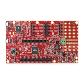
CURIOSITY DEVELOPMENT BOARD USER’S GUIDE Chapter 1. Introduction The dsPIC33CH Curiosity Development Board (DM330028) is intended as a cost-effective development and demonstration platform for the dsPIC33CH128MP508 family of dual core, high-performance Digital Signal Controllers. Some of the board hardware features are highlighted in Figure 1-1. -
Page 12: Schematics And Bill Of Materials (Bom)
Curiosity Development Board User’s Guide SCHEMATICS AND BILL OF MATERIALS (BOM) Schematics and the BOM for the dsPIC33CH Curiosity Development Board are located in (BOM)”, respectively. Appendix A. “Schematics” Appendix B. “Bill of Materials Advance Information 2018 Microchip Technology Inc. -
Page 13: Chapter 2. Hardware
(when limited in current level), but are a USB compliance violation. They can interfere with the host operation, especially when the host is unpowered. This scenario can be avoided, however, via D1. Advance Information 2018 Microchip Technology Inc. DS50002762A-page 13... -
Page 14: Using The Programmed Demo Firmware
PKOB circuit relies on standard OS provided HID drivers, and therefore, driver instal- lation should be fully automatic. When plugged in, the PKOB programmer/debugger tool can be selected from the MPLAB X project properties page by selecting the device under: Hardware Tools>Microchip Starter Kits>Starter Kits (PKOB)>dsPIC33CH Curio…, as shown in Figure 2-1. -
Page 15: Using The Isolated Usb-Uart Interface
J11 – This is a female I/O pin access header used for accessing the U1 microcontroller I/O pins. J12 – This is a female I/O pin access header used for accessing the U1 microcontroller I/O pins. Advance Information 2018 Microchip Technology Inc. DS50002762A-page 15... -
Page 16: Smps Hardware Overcurrent Protection
Curiosity Development Board User’s Guide J13 – This jumper sets the effective resistor divider feedback ratio for the SMPS output voltage when it is measured by the U1 ADC. When the SMPS is used to generate rel- atively low voltages (ex: 0V-6.5V), it is suggested to keep J13 capped to maximize feedback circuit sensitivity. -
Page 17: Smps Hardware Overvoltage Protection
DC voltage. Op amp U8 buffers the DC voltage, providing a low-impedance firmware adjustable DAC, where the output voltage is based on the PWM duty cycle provided to the circuit. Advance Information 2018 Microchip Technology Inc. DS50002762A-page 17... -
Page 18: Transient Load Tester Circuit
Curiosity Development Board User’s Guide 2.5.5 Transient Load Tester Circuit The MOSFET Q8 and surrounding components implement an adjustable constant-current sink that can be periodically pulsed on for a few milliseconds at a time to generate momentary SMPS output load transient pulses. During control loop firm- ware development, it is often desirable to study the control system behavior in response to large signal step changes. -
Page 19: Low-Side Current Sensing
PGA to reflect the true current through the sense resistors, unless the overall gain of the complete circuit is directly measured and factored into the computations in the firmware. Advance Information 2018 Microchip Technology Inc. DS50002762A-page 19... -
Page 20: High-Side Current Sensing
Curiosity Development Board User’s Guide HIGH-SIDE CURRENT SENSING The SMPS on-time current can be measured by the voltage developed across the high-side current sense resistors, R59 and R74. However, the ISENSEH signal is referenced to the +5V input rail of the SMPS circuit (not to ground), which prevents it from being measured directly by the ADC or comparators in the microcontroller U1. -
Page 21: Appendix A. Schematics
CURIOSITY DEVELOPMENT BOARD USER’S GUIDE Appendix A. Schematics The schematics for the dsPIC33CH Curiosity Development Board (DM330028) are shown in Figure 1 through Figure Advance Information 2018 Microchip Technology Inc. DS50002762A-page 21... - Page 22 FIGURE A-1: dsPIC33CH CURIOSITY BOARD SCHEMATIC REV. 1.0 (SHEET ONE OF FOUR) MCLR MCLR U1VDD AN0/CMP1A/RA0 RA0_POT AN1/S1AN15/RA1 RA1_VINSENSE Net Tie AN2/S1AN16/RA2 RA2_TRANSIENTFB RE7_S1 AN3/IBIAS0/S1AN0/S1CMP1A/S1PGA1P1/RA3 RA3_ISENSEH AN4/IBIAS1/S1MCLR3/S1AN1/S1CMP2A/S1PGA2P1/S1PGA3P2/RA4 RA4_S1MCLR3 0603 RB0_OSCI Current measurement point Buttons DS C 6011J I1A-008.0000 0.1 μF...
- Page 23 FIGURE A-2: dsPIC33CH CURIOSITY BOARD LAYOUT SCHEMATIC REV. 1.0 (SHEET TWO OF FOUR) Isolated USB-UART Interface USB micro-B TH/SMT I/O Pin Access Headers J 16 U9_V DD U9_V DD U9D_N RD12_S1PGA2P2 RC1_VOUTFB RA1_VINSENSE U9D_P RC6_RSTB RA0_POT RC3_MOSIA RB0_OSCI RD13 RC0_PWMDACFB...
- Page 24 FIGURE A-3: dsPIC33CH CURIOSITY BOARD LAYOUT SCHEMATIC REV. 1.0 (SHEET THREE OF FOUR) Input voltage mo nitoring High-side current sense level shifter Configurable Buck, Boost or Buck/Boost Test Circuit For Buck Mode: PWM Q6, Drive Q2 DC OFF For Boost Mode: Drive Q6 DC OFF (logic high or tri-state) , PW M Q2...
- Page 25 FIGURE A-4: dsPIC33CH CURIOSITY BOARD LAYOUT SCHEMATIC REV. 1.0 (SHEET FOUR OF FOUR) 4.7k /MCLR PICkit™ On-Board ICSPDAT PK_PGD ICSPCLK PK_PGC 10 μF 3.57k 0.1 μF 0603 Target ICSP™ Signals 0805 MCLR PGED1/AN0/V +/RP0/PMA6/CN2/RB0 ENVREG PGEC1/AN1/V -/RP1/CN3/RB1 VDD_SENSE 0603 AN2/C2INB/VMIO/RP13/CN4/RB2...
- Page 26 Curiosity Development Board User’s Guide NOTES: Advance Information 2018 Microchip Technology Inc. DS50002762A-page 26...
-
Page 27: Appendix B. Bill Of Materials
CURIOSITY DEVELOPMENT BOARD USER’S GUIDE Appendix B. Bill of Materials (BOM) TABLE B-1: dsPIC33CH CURIOSITY DEVELOPMENT BOARD BILL OF MATERIALS Qty. Designator Description Mfg. 1 Mfg. 1 Part # Mfg. 2 Mfg. 2 Part # C1, C2, C3, C4, C6, Capacitor Ceramic, 0.1 µF, 25V,... - Page 28 Curiosity Development Board User’s Guide TABLE B-1: dsPIC33CH CURIOSITY DEVELOPMENT BOARD BILL OF MATERIALS (CONTINUED) Qty. Designator Description Mfg. 1 Mfg. 1 Part # Mfg. 2 Mfg. 2 Part # Resistor TKF, 2.2k, 1%, 1/10W, Panasonic - ERJ-3EKF2201V SMD, 0603...
- Page 29 Bill of Materials (BOM) TABLE B-1: dsPIC33CH CURIOSITY DEVELOPMENT BOARD BILL OF MATERIALS (CONTINUED) Qty. Designator Description Mfg. 1 Mfg. 1 Part # Mfg. 2 Mfg. 2 Part # IC Logic Gate, UHS, 2-INP, Fairchild NC7SZ57P6X ® SC70-6 Semiconductor Semiconductor...
-
Page 30: Worldwide Sales And Service
Tel: 46-31-704-60-40 Tel: 631-435-6000 Sweden - Stockholm San Jose, CA Tel: 46-8-5090-4654 Tel: 408-735-9110 UK - Wokingham Tel: 408-436-4270 Tel: 44-118-921-5800 Canada - Toronto Fax: 44-118-921-5820 Tel: 905-695-1980 Fax: 905-695-2078 Advance Information 2018 Microchip Technology Inc. DS50002762A-page 30 10/25/17...
Need help?
Do you have a question about the dsPIC33CH and is the answer not in the manual?
Questions and answers