
Related Manuals for Microchip Technology DT100108


Summary of Contents for Microchip Technology DT100108
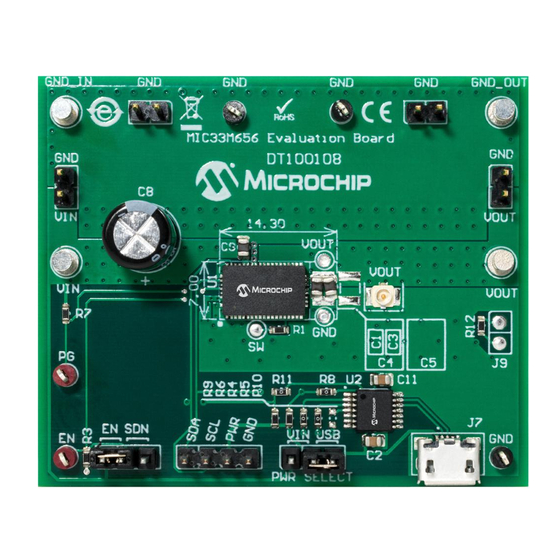
- Page 1 MIC33M656 Evaluation Board User’s Guide 2019 Microchip Technology Inc. DS50002914A...
- Page 2 Technology, and Symmcom are registered trademarks of Microchip Technology Inc. in other countries. GestIC is a registered trademark of Microchip Technology Germany II GmbH & Co. KG, a subsidiary of Microchip Technology Inc., in other countries. All other trademarks mentioned herein are property of their respective companies.
-
Page 3: Table Of Contents
A.6 Board – Signal Layer 1 ................32 A.7 Board – Signal Layer 2 ................33 A.8 Board – Bottom Copper ................33 A.9 Board – Bottom Copper and Silk ..............34 A.10 Board – Bottom Silk ................... 34 2019 Microchip Technology Inc. DS50002914A-page 3... - Page 4 MIC33M656 Evaluation Board User’s Guide Appendix B. Bill of Materials (BOM) ................35 Appendix C. MIC33M656 Internal Registers...............37 C.1 Register Map and I C Programmability ............37 Worldwide Sales and Service ..................42 2019 Microchip Technology Inc. DS50002914A-page 4...
-
Page 5: Preface
MIC33M656 Evaluation Board. • Appendix B. “Bill of Materials (BOM)” – Lists the parts used to build the MIC33M656 Evaluation Board. • Appendix C. “MIC33M656 Internal Registers” – Describes the MIC33M656 device’s internal registers. 2019 Microchip Technology Inc. DS50002914A-page 5... -
Page 6: Conventions Used In This Guide
Curly brackets and pipe Choice of mutually exclusive errorlevel {0|1} character: { | } arguments; an OR selection Ellipses... Replaces repeated text var_name [, var_name...] Represents code supplied by void main (void) user { ... 2019 Microchip Technology Inc. DS50002914A-page 6... -
Page 7: Recommended Reading
Technical support is available through the website at: http://www.microchip.com/support. DOCUMENT REVISION HISTORY Revision A (September 2019) • Initial Release of this Document. 2019 Microchip Technology Inc. DS50002914A-page 7... - Page 8 MIC33M656 Evaluation Board User’s Guide NOTES: 2019 Microchip Technology Inc. DS50002914A-page 8...
-
Page 9: Chapter 1. Product Overview
More detailed information regarding the capabilities of the MIC33M656 are available in the “MIC33M656 Data Sheet”. 1.0V/6A 2.4V to 5.5V AUX_PV 10 µF 47 µF 47 µF MIC33M656 PGND Enable AGND AUX_GND FIGURE 1-1: Typical MIC33M656 Step-Down Application. 2019 Microchip Technology Inc. DS50002914A-page 9... -
Page 10: What Is The Mic33M656 Evaluation Board
C monitor GUI allows comprehensive control and status reporting with the MIC33M656. CONTENTS OF THE MIC33M656 EVALUATION BOARD KIT The MIC33M656 Evaluation Board kit includes: • MIC33M656 Evaluation Board (DT100108) • Important Information Sheet 2019 Microchip Technology Inc. DS50002914A-page 10... -
Page 11: Chapter 2. Installation And Operation
Note 1: Three-way jumper fitted for selection of I C pull-up voltage. 2: I C bus (SDA, SCL), EN control and PG status via MCP2221 USB bridge. FIGURE 2-1: MIC33M656 Step-Down Regulator with MCP2221 I C Bridge. 2019 Microchip Technology Inc. DS50002914A-page 11... -
Page 12: Features
“MIC33M656 Data Sheet”. The Evaluation Board carries the HAYMP option, whose default output voltage is 1.0V. All of the device options may be fitted on the board, as is. 2019 Microchip Technology Inc. DS50002914A-page 12... - Page 13 A U.FL connector is also available for the same purpose. 2019 Microchip Technology Inc. DS50002914A-page 13...
- Page 14 (i.e., across resistor R12) and connect the A (CH1) and B (CH2) channels to J9 Pin 1 and J9 Pin 2, respectively, or as indicated by the operating instructions of the particular loop gain analyzer in use. 2019 Microchip Technology Inc. DS50002914A-page 14...
- Page 15 GP0 active button, the MIC33M656 is enabled or disabled. Note: When using MCP2221 GPIO control, remove any low-impedance connec- tion between the EN pin and V or GND (e.g., a jumper on the J6 header) as this may cause undefined behavior. 2019 Microchip Technology Inc. DS50002914A-page 15...
- Page 16 +125°C due to internal power dissipation. Continuous operation above the maximum operating limits stated in the data sheet should be avoided. 2019 Microchip Technology Inc. DS50002914A-page 16...
-
Page 17: Chapter 3. Gui Installation And Operation
5. Double click the setup.exe file to open the InstallShield Wizard window and wait for the extraction to complete. If required, the installation can be stopped by pressing the Cancel button. 2019 Microchip Technology Inc. DS50002914A-page 17... - Page 18 Starting the I C Monitor Graphical User Interface Installation. 7. The installation path can be changed, although it is recommended to keep the default path. Click Next to continue. FIGURE 3-2: Selecting the Destination Folder. 2019 Microchip Technology Inc. DS50002914A-page 18...
- Page 19 8. In the Ready to Install the Program window, click the Install button and wait for the application to proceed with the installation. The progress can be observed in the “Status” bar. FIGURE 3-3: Installing the I C Monitor Graphical User Interface. 2019 Microchip Technology Inc. DS50002914A-page 19...
-
Page 20: I 2 C Monitor Graphical User Interface Uninstall
To uninstall, go to Windows Start>Control Panel>Uninstall a program>I2CMonitor. The C Monitor GUI will automatically close once the uninstallation process is complete. FIGURE 3-5: Uninstalling the I C Monitor Graphical User Interface. 2019 Microchip Technology Inc. DS50002914A-page 20... -
Page 21: Chapter 4. Gui Description
C Generic Register View MIC33M656 I Programmable Features MIC33M656 I MIC33M656 Status Bar Control by MCP2221 GP0 Output Progress Bar Diagnostic FIGURE 4-1: C Monitor Graphical User Interface Main Window – MIC33M656 View. 2019 Microchip Technology Inc. DS50002914A-page 21... -
Page 22: The Graphical User Interface
From the Settings menu, add a new custom board to be automatically detected and switch to its profile. To do this, go to Settings>Device descriptors, and in the Descriptors window, add the desired “Board” descriptor and select the desired “Device” profile. FIGURE 4-3: Custom Board Menu. 2019 Microchip Technology Inc. DS50002914A-page 22... - Page 23 Once a valid address is detected, clicking the Connect button will initialize the connection with the device, and the registers will be available for read and write operations. 2019 Microchip Technology Inc. DS50002914A-page 23...
- Page 24 Register area This section shows the current status of the registers’ address and their content. The specific registers for MIC33M656 are described in Appendix C. “MIC33M656 Internal Registers”. 2019 Microchip Technology Inc. DS50002914A-page 24...
- Page 25 MIC33M656 through Enable pin or check the box to enable the MIC33M656 regulator. This area of the GUI allows the user to modify the device features. For additional information on the part, refer to the data sheet. 2019 Microchip Technology Inc. DS50002914A-page 25...
- Page 26 In order to simplify this, an auxiliary trigger signal is provided on pin GP2 of the MCP2221. This signal is triggered for each user Read/Write command. 2019 Microchip Technology Inc. DS50002914A-page 26...
- Page 27 STATUS LABELS Status Label Description STATUS: Connected! This message is shown when the GUI connects to a device. STATUS: Disconnected! This message is shown when the GUI does not detect a connected device. 2019 Microchip Technology Inc. DS50002914A-page 27...
- Page 28 MIC33M656 Evaluation Board User’s Guide NOTES: 2019 Microchip Technology Inc. DS50002914A-page 28...
-
Page 29: Appendix A. Schematic And Layouts
Board – Top Copper • Board – Signal Layer 1 • Board – Signal Layer 2 • Board – Bottom Copper • Board – Bottom Copper and Silk • Board – Bottom Silk 2019 Microchip Technology Inc. DS50002914A-page 29... -
Page 30: Board - Schematic
BOARD – SCHEMATIC USB 2.0 Micro-B Female HDR-2.54 Male 1x3 4.7 μF 4.7 μF UART RX UART TX 0805 0805 0603 0603 JP2 should be mounted on 1-2 pins J8 MCP2221A 49.9R 0603 EP (PV 22 μF 470 μF AUX_PV 0805 AUX_PV Net Tie... -
Page 31: Board - Top Silk
Schematic and Layouts BOARD – TOP SILK BOARD – TOP COPPER AND SILK 2019 Microchip Technology Inc. DS50002914A-page 31... -
Page 32: Board - Top Copper
MIC33M656 Evaluation Board User’s Guide BOARD – TOP COPPER BOARD – SIGNAL LAYER 1 2019 Microchip Technology Inc. DS50002914A-page 32... -
Page 33: Board - Signal Layer 2
Schematic and Layouts BOARD – SIGNAL LAYER 2 BOARD – BOTTOM COPPER 2019 Microchip Technology Inc. DS50002914A-page 33... -
Page 34: Board - Bottom Copper And Silk
MIC33M656 Evaluation Board User’s Guide BOARD – BOTTOM COPPER AND SILK A.10 BOARD – BOTTOM SILK 2019 Microchip Technology Inc. DS50002914A-page 34... -
Page 35: Mic33M656 Evaluation Board User's Guide
Resistor, TKF, 10R, 1%, 1/10W, Panasonic ERJ3EKF10R0V SMD, 0603 Microchip Analog Switcher Buck, Microchip Technology Inc. MIC33M656-HAYMP 0.6V to 3.3V, 6A, MIC33M656-HAYMP-TR, QFN-53 Microchip Interface, USB, I Microchip Technology Inc. MCP2221A-I/ST UART, MCP2221A-I/ST, TSSOP-14 2019 Microchip Technology Inc. DS50002914A-page 35... - Page 36 77311-118-02LF ® DO NOT POPULATE Panasonic ERJ-3GSY0R00V Note 1: The components listed in this Bill of Materials are representative of the PCB assembly. The released BOM used in manufacturing uses all RoHS-compliant components. 2019 Microchip Technology Inc. DS50002914A-page 36...
-
Page 37: Appendix C. Mic33M656 Internal Registers
10 = 2 ms 11 = 3 ms bit 1 EN_INT: Enable Bit Register Control 0 = Register controlled 1 = Enable pin controlled bit 0 EN_CON: Enable Control 0 = Off 1 = On 2019 Microchip Technology Inc. DS50002914A-page 37... - Page 38 0101 = 1200 0110 = 1400 0111 = 1600 1000 = 1800 1001 = 2000 1010 = 2200 1011 = 2400 1100 = 2600 1101 = 2800 1110 = 3000 1111 = 3200 2019 Microchip Technology Inc. DS50002914A-page 38...
- Page 39 0xFD = 1.27V 0x7E = 0.635V 0x9E = 0.795V 0xBE = 0.955V 0xDE = 1.115V 0xFE = 1.275V 0x7F = 0.64V 0x9F = 0.8V 0xBF = 0.96V 0xDF = 1.12V 0xFF = 1.28V 2019 Microchip Technology Inc. DS50002914A-page 39...
- Page 40 0x9E = 1.9V 0xBE = 2.54V 0xDE = 3.18V 0xFE = 3.82V 0x3F = 0.64V 0x5F = 0.96V 0x7F = 1.28V 0x9F = 1.92V 0xBF = 2.56V 0xDF = 3.2V 0xFF = 3.84V 2019 Microchip Technology Inc. DS50002914A-page 40...
- Page 41 1 = Fault bit 1 LATCH_OFF: Overcurrent or Overtemperature Output Latch Off 0 = No Fault 1 = Fault bit 0 PG: Power Good 0 = Power not good 1 = Power good 2019 Microchip Technology Inc. DS50002914A-page 41...
-
Page 42: Worldwide Sales And Service
New York, NY Tel: 46-31-704-60-40 Tel: 631-435-6000 Sweden - Stockholm San Jose, CA Tel: 46-8-5090-4654 Tel: 408-735-9110 UK - Wokingham Tel: 408-436-4270 Tel: 44-118-921-5800 Canada - Toronto Fax: 44-118-921-5820 Tel: 905-695-1980 Fax: 905-695-2078 2019 Microchip Technology Inc. DS50002914A-page 42 05/14/19...
Need help?
Do you have a question about the DT100108 and is the answer not in the manual?
Questions and answers