
Related Manuals for Microchip Technology dsPICDEM MCSM


Summary of Contents for Microchip Technology dsPICDEM MCSM
- Page 1 MCSM Development Board User’s Guide © 2009 Microchip Technology Inc. DS70610A Arrow.com. Downloaded from...
- Page 2 Endurance, TSHARC, UniWinDriver, WiperLock and ZENA are trademarks of Microchip Technology Incorporated in the U.S.A. and other countries. SQTP is a service mark of Microchip Technology Incorporated in the U.S.A. All other trademarks mentioned herein are property of their respective companies.
-
Page 3: Table Of Contents
3.3 Board Connectors ..................24 3.4 User Interface Hardware ................27 Chapter 4. Troubleshooting 4.1 Common Problems ..................29 Appendix A. Board Layout and Schematics Appendix B. Electrical Specifications © 2009 Microchip Technology Inc. DS70610A-page 3 Arrow.com. Arrow.com. Arrow.com. Downloaded from... - Page 4 MCSM Development Board User’s Guide NOTES: © 2009 Microchip Technology Inc. DS70610A-page 4 Arrow.com. Arrow.com. Arrow.com. Arrow.com. Downloaded from Downloaded from Downloaded from Downloaded from...
-
Page 5: Customer Support
• Customer Support • Document Revision History DOCUMENT LAYOUT This user’s guide describes how to use the dsPICDEM MCSM Development Board. The document is organized as follows: • Chapter 1. “Introduction” – This chapter introduces the dsPICDEM MCSM Development Board and provides a brief overview of its features. -
Page 6: Board Layout
MCSM Development Board. • Appendix B. “Electrical Specifications” – This appendix provides pertinent electrical specifications for the dsPICDEM MCSM Development Board. © 2009 Microchip Technology Inc. DS70610A-page 6 Arrow.com. -
Page 7: Documentation Conventions
{ | } arguments; an OR selection Ellipses... Replaces repeated text var_name [, var_name...] Represents code supplied by void main (void) user { ... © 2009 Microchip Technology Inc. DS70610A-page 7 Arrow.com. Arrow.com. Arrow.com. Arrow.com. Arrow.com. Arrow.com. Arrow.com. Downloaded from... - Page 8 Interim software releases are available at the Microchip web site. RECOMMENDED READING This user’s guide describes how to use the dsPICDEM MCSM Development Board. The device-specific data sheets contain current information on programming the specific microcontroller or digital signal controller devices. Other useful documents are listed below.
- Page 9 • Programmers – The latest information on Microchip programmers. These include ® ® the MPLAB PM3 and PRO MATE II device programmers and the PICSTART Plus and PICkit™ 1development programmers. © 2009 Microchip Technology Inc. DS70610A-page 9 Arrow.com. Arrow.com. Arrow.com. Arrow.com.
- Page 10 Technical support is available through the web site at: http://support.microchip.com DOCUMENT REVISION HISTORY Revision A (September 2009) This is the initial released revision of this document. © 2009 Microchip Technology Inc. DS70610A-page 10 Arrow.com. Arrow.com. Arrow.com.
-
Page 11: Chapter 1. Introduction
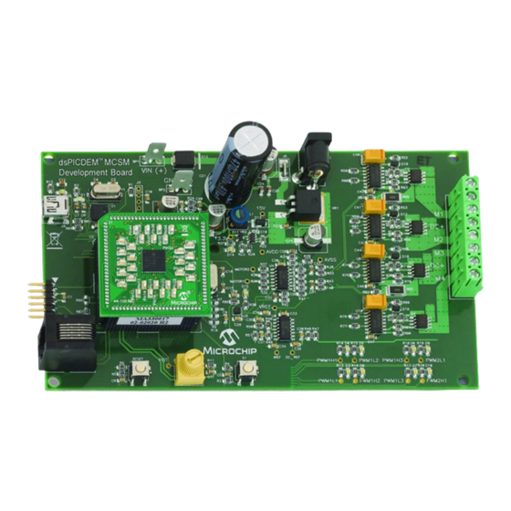
USER’S GUIDE Chapter 1. Introduction The dsPICDEM MCSM Development Board is targeted to control both unipolar and bipolar stepper motors with no hardware configuration changes. This flexible and cost-effective board can be configured in different ways for use with Microchip’s specialized dsPIC33F Motor Control Digital Signal Controllers (DSCs). - Page 12 MCSM Development Board User’s Guide FIGURE 1-1: dsPICDEM MCSM DEVELOPMENT BOARD © 2009 Microchip Technology Inc. DS70610A-page 12 Arrow.com. Arrow.com. Arrow.com. Arrow.com. Arrow.com. Arrow.com. Arrow.com. Arrow.com. Arrow.com. Arrow.com. Arrow.com. Arrow.com. Downloaded from Downloaded from Downloaded from Downloaded from Downloaded from...
-
Page 13: Features
- ICSP connector for programming the PIC18LF2450 USB-to-UART Bridge (J3) WHAT’S INCLUDED Note: The MCSM Development Board is available in two configurations: • dsPICDEM MCSM Development Board • dsPICDEM MCSM Development Board Kit © 2009 Microchip Technology Inc. DS70610A-page 13 Arrow.com. Arrow.com. -
Page 14: Reference Documents And Webinars
REFERENCE DOCUMENTS AND WEBINARS In addition to the documents listed in the “Recommended Reading” section, the following are also available from Microchip to support the use of the dsPICDEM MCSM Development Board. • AN907 “Stepping Motors Fundamentals”... -
Page 15: Chapter 2. Getting Started
USER’S GUIDE Chapter 2. Getting Started This chapter describes how to set up the dsPICDEM MCSM Development Board hardware and software; and how to run the included demonstration software. Refer to Chapter 3. “Hardware” for detailed information on the board and its components. -
Page 16: Programming And Debugging Application Code
The following procedure describes how to program the dsPICDEM MCSM Development Board in Debug mode: 1. Place the dsPICDEM MCSM Development Board on a sturdy insulated platform. 2. Make sure that the dsPIC33FJ32MC204 device or an appropriate PIM is mounted in the respective socket. -
Page 17: Chapter 3. Hardware
MCSM DEVELOPMENT BOARD USER’S GUIDE Chapter 3. Hardware This chapter describes the hardware used in the dsPICDEM MCSM Development Board. Topics covered include: • Hardware Architecture • PIM Configuration • Board Connectors • User Interface Hardware HARDWARE ARCHITECTURE The dsPIC DSC devices feature an 8-channel, high-speed PWM with Complementary mode output, a programmable ADC trigger on the PWM reload cycle, digital dead time control, internal shoot-through protection and hardware fault shutdown. -
Page 18: Mosfet Pwm Assignment
3.1.1 Power Stage The dsPICDEM MCSM Development Board features two full-bridge inverters to accom- modate a bipolar stepper motor. MOSFET gate signals are powered from a 15V per- manent supply while the full-bridge inverters can be powered from a supply up to 80V. -
Page 19: Amplifier Gain Calculation Formula
PWM shutdown. Each phase current is amplified and then compared with a fixed “safe” current value. A value of 1.7A is set for the dsPICDEM MCSM Development Board; however, the user can change this limit by changing the resistor divider made by R48 and R51. -
Page 20: Pim Configuration
• dsPIC33FJ32MC204 PIM (MA330017) • dsPIC33FJ128MC804 PIM (MA330018) Table 3-1, Table 3-2 and Table 3-3 describe the PIM configuration details. The dsPIC33FJ32MC204 and dsPIC33FJ128MC804 PIMs are pin-compatible and share the same table. © 2009 Microchip Technology Inc. DS70610A-page 20 Arrow.com. Arrow.com. Arrow.com. -
Page 21: Dspic33Fj256Mc710
FAULT_1 or PWM2L1 signals by soldering the appropriate resistor as follows: • For FAULT_1 : Remove R87 and Solder R86 • For PWM2L1 : Remove R86 and Solder R87 (Default) © 2009 Microchip Technology Inc. DS70610A-page 21 Arrow.com. -
Page 22: Dspic33Fj12Mc202
Solder R15 Note 1: No hardware changes are needed if the standard dsPICDEM MCSM Development Board is used with a standard dsPIC33FJ12MC202 PIM. PIM Pin 19 can be configured for FAULT_1 or PWM2L1 signals by soldering the appropriate resistor as follows: •... -
Page 23: Dspic33Fj128Mc804
Solder R8 Note 1: No hardware changes are needed if the standard dsPICDEM MCSM Development Board is used with a standard dsPIC33FJ12MC204 or dsPIC33FJ128MC804 PIM. PIM Pin 19 can be configured for FAULT_1 or PWM2L1 signals by soldering the appropriate resistor as follows: •... -
Page 24: Board Connectors
MCSM Development Board. Table 3-4 describes the hardware connection between the ® PICkit™ 3, MPLAB ICD 3 or MPLAB REAL ICE™ In-Circuit Emulator, the power supply, and the dsPICDEM MCSM Development Board connectors. FIGURE 3-3: dsPICDEM MCSM DEVELOPMENT BOARD USER INTERFACE COMPONENTS D3-D10... -
Page 25: Dc Bus Power Supply Connector (J5 And J7)
3.3.1 Input Power Connector (J6, BP1-BP2) The dsPICDEM MCSM Development Board receives the power for control circuits from a +24V power supply. The 24V supply is always needed as it supplies 15V and 3.3V necessary for the dsPIC DSC and for the interface between the dsPIC DSC and the power stage. -
Page 26: Mosfet Driver
PWM output for wire 3 top switch PWM1L3 PWM output for wire 3 bottom switch PWM2H1 PWM output for wire 4 bottom switch PWM2L1 PWM output for wire 4 top switch © 2009 Microchip Technology Inc. DS70610A-page 26 Arrow.com. Arrow.com. Arrow.com. Arrow.com. Arrow.com. -
Page 27: User Interface Hardware
Hardware USER INTERFACE HARDWARE The dsPICDEM MCSM Development Board consists of the following push buttons, LEDs and potentiometers: • One push button • One potentiometer • Eight PWM LEDs • One power-on status LED • Two USB LEDs • One Fault LED •... - Page 28 MCSM Development Board User’s Guide NOTES: © 2009 Microchip Technology Inc. DS70610A-page 28 Arrow.com. Arrow.com. Arrow.com. Arrow.com. Arrow.com. Arrow.com. Arrow.com. Arrow.com. Arrow.com. Arrow.com. Arrow.com. Arrow.com. Arrow.com. Arrow.com. Arrow.com. Arrow.com. Arrow.com. Arrow.com. Arrow.com. Arrow.com. Arrow.com. Arrow.com. Arrow.com. Arrow.com. Arrow.com. Arrow.com.
-
Page 29: Chapter 4. Troubleshooting
USER’S GUIDE Chapter 4. Troubleshooting This chapter provides information for troubleshooting problems encountered while using the dsPICDEM MCSM Development Board. COMMON PROBLEMS 1. Problem: USB connection in DMCI fail (amber and green LEDs are ON) This condition is accompanied by the following error message:... - Page 30 MCSM Development Board User’s Guide NOTES: © 2009 Microchip Technology Inc. DS70610A-page 30 Arrow.com. Arrow.com. Arrow.com. Arrow.com. Arrow.com. Arrow.com. Arrow.com. Arrow.com. Arrow.com. Arrow.com. Arrow.com. Arrow.com. Arrow.com. Arrow.com. Arrow.com. Arrow.com. Arrow.com. Arrow.com. Arrow.com. Arrow.com. Arrow.com. Arrow.com. Arrow.com. Arrow.com. Arrow.com. Arrow.com.
-
Page 31: Appendix A. Board Layout And Schematics
MCSM DEVELOPMENT BOARD USER’S GUIDE Appendix A. Board Layout and Schematics FIGURE A-1: dsPICDEM™ MCSM DEVELOPMENT BOARD LAYOUT (TOP) © 2009 Microchip Technology Inc. DS70610A-page 31 Arrow.com. Arrow.com. Arrow.com. Arrow.com. Arrow.com. Arrow.com. Arrow.com. Arrow.com. Arrow.com. Arrow.com. Arrow.com. Arrow.com. Arrow.com. - Page 32 MCSM Development Board User’s Guide FIGURE A-2: dsPICDEM™ MCSM DEVELOPMENT BOARD SCHEMATIC (SHEET 1 OF 3) © 2009 Microchip Technology Inc. DS70610A-page 32 Arrow.com. Arrow.com. Arrow.com. Arrow.com. Arrow.com. Arrow.com. Arrow.com. Arrow.com. Arrow.com. Arrow.com. Arrow.com. Arrow.com. Arrow.com. Arrow.com. Arrow.com. Arrow.com.
- Page 33 Board Layout and Schematics FIGURE A-3: dsPICDEM™ MCSM DEVELOPMENT BOARD SCHEMATIC (SHEET 2 OF 3) © 2009 Microchip Technology Inc. DS70610A-page 33 Arrow.com. Arrow.com. Arrow.com. Arrow.com. Arrow.com. Arrow.com. Arrow.com. Arrow.com. Arrow.com. Arrow.com. Arrow.com. Arrow.com. Arrow.com. Arrow.com. Arrow.com. Arrow.com. Arrow.com. Arrow.com.
- Page 34 MCSM Development Board User’s Guide FIGURE A-4: dsPICDEM™ MCSM DEVELOPMENT BOARD SCHEMATIC (SHEET 3 OF 3) © 2009 Microchip Technology Inc. DS70610A-page 34 Arrow.com. Arrow.com. Arrow.com. Arrow.com. Arrow.com. Arrow.com. Arrow.com. Arrow.com. Arrow.com. Arrow.com. Arrow.com. Arrow.com. Arrow.com. Arrow.com. Arrow.com. Arrow.com.
-
Page 35: Appendix B. Electrical Specifications
MCSM DEVELOPMENT BOARD USER’S GUIDE Appendix B. Electrical Specifications This appendix provides important electrical specifications for the dsPICDEM MCSM Development Board. TABLE B-1: DC INPUT RATING Parameter Condition Unit Power supply connected to J6 — Power supply connected to BP1-BP2... - Page 36 MCSM Development Board User’s Guide NOTES: © 2009 Microchip Technology Inc. DS70610A-page 36 Arrow.com. Arrow.com. Arrow.com. Arrow.com. Arrow.com. Arrow.com. Arrow.com. Arrow.com. Arrow.com. Arrow.com. Arrow.com. Arrow.com. Arrow.com. Arrow.com. Arrow.com. Arrow.com. Arrow.com. Arrow.com. Arrow.com. Arrow.com. Arrow.com. Arrow.com. Arrow.com. Arrow.com. Arrow.com. Arrow.com.
- Page 37 ........23 dsPIC33FJ12MC202 ........22 dsPIC33FJ256MC710 ........21 dsPIC33FJ32MC204 ........23 Plug-In Module (PIM) ..........11 Power Stage ............18 MOSFET Driver ..........18 Switching Topology........... 18 © 2009 Microchip Technology Inc. DS70610A-page 37 Arrow.com. Arrow.com. Arrow.com. Arrow.com. Arrow.com. Arrow.com.
- Page 38 Fax: 86-29-8833-7256 Fax: 66-2-694-1350 Fax: 408-961-6445 China - Zhuhai Toronto Tel: 86-756-3210040 Mississauga, Ontario, Fax: 86-756-3210049 Canada Tel: 905-673-0699 Fax: 905-673-6509 03/26/09 © 2009 Microchip Technology Inc. DS70610A-page 38 Arrow.com. Arrow.com. Arrow.com. Arrow.com. Arrow.com. Arrow.com. Arrow.com. Arrow.com. Arrow.com. Arrow.com. Arrow.com.
Need help?
Do you have a question about the dsPICDEM MCSM and is the answer not in the manual?
Questions and answers