Table of Contents
Advertisement
Quick Links
Advertisement
Table of Contents

Related Manuals for Aaeon EMB-H81A


Summary of Contents for Aaeon EMB-H81A
- Page 1 EMB-H81A...
- Page 2 E9305 Revised Edition v2 April 2014 Copyright Notice This document is copyrighted, 2014. All rights are reserved. The original manufacturer reserves the right to make improvements to the products described in this manual at any time without notice. No part of this manual may be reproduced, copied, translated, or transmitted in any form or by any means without the prior written permission of the original manufacturer.
-
Page 3: Table Of Contents
Contents Chapter 1 Product overview Package contents................. 1-1 Features ..................1-1 Specifications ................1-2 Chapter 2 Motherboard information Before you proceed ..............2-1 Motherboard layout ..............2-2 Screw size ..................2-4 2.3.1 Component side .............. 2-4 2.3.2 Solder side ..............2-5 Central Processing Unit (CPU) ........... - Page 4 3.3.6 NCT6791D Super IO Configuration ........ 3-6 3.3.7 NCT5104D Second Super IO Configuration ....3-7 3.3.8 NCT6791D HW Monitor ..........3-7 3.3.9 Dynamic Digital IO ............3-8 3.3.10 Power Management ............3-8 Chipset menu ................3-9 3.4.1 System Agent (SA) Configuration ........3-9 3.4.2 PCH-IO Configuration ........... 3-10 Boot menu .................. 3-11 3.5.1 Boot Configuration ............
-
Page 5: Chapter 1 Product Overview
Chapter 1 Product overview Package contents Check your industrial motherboard package for the following items. 1 x Industrial Motherboard 1 x SATA Cable 1 x I/O Shield 1 x Support CD If any of the above items is damaged or missing, contact your distributor or sales representative immediately. -
Page 6: Specifications
6.7 in. x 6.7 in. (17.0 cm x 17.0 cm) Gross weight 1.1 lb (0.5 Kg) Operating F~140 F (0 C~60 temperature Storage temperature F~185 F (-40 C~85 Operating humidity 0%~90% relative humidity, non-condensing Power compliance Compliant with Eup/ErP Certificate CE/FCC (continued on the next page) EMB-H81A... - Page 7 DISPLAY Chipset Intel Graphics Media Accelerator ® Resolution Up to 1920x1200@60Hz for VGA Up to 1920x1200@60Hz for DVI Up to 1920x 1200@60Hz, Dual Channel 18/24 bit Support LVDS Output interface 1 x DVI 1 x VGA 1 x LVDS Storage 2 x SATA 6.0Gb/s ports 2 x SATA 3.0Gb/s ports Serial port...
- Page 8 EMB-H81A...
-
Page 9: Chapter 2 Motherboard Information
Chapter 2 Motherboard information Before you proceed Take note of the following precautions before you install motherboard components or change any motherboard settings. CAUTION! • Unplug the power cord from the wall socket before touching any component. • Before handling components, use a grounded wrist strap or touch a safely grounded object or a metal object, such as the power supply case, to avoid damaging them due to static electricity. -
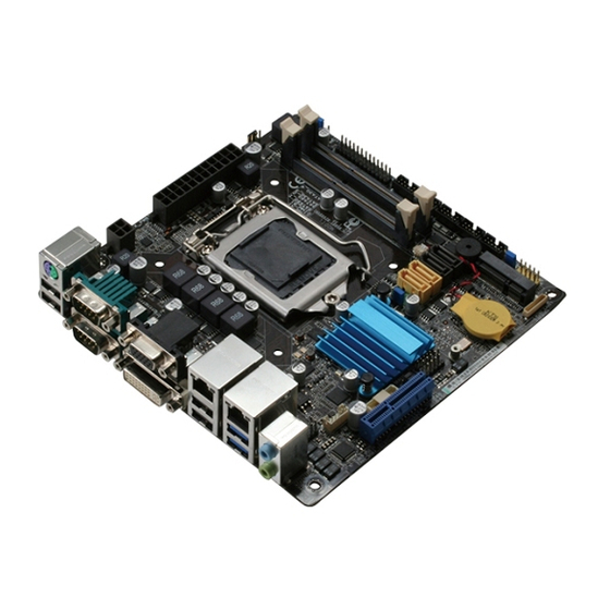
Page 10: Motherboard Layout
17.0cm(6.7in) CPU_FAN1 KBMS_USB89 EATX_PWR2 EATX_PWR1 LPT1 COM1_V1 Place this side towards the rear of the chassis 1442 BATTERY LAN2_USB34 8111F Nuvoton NCT5104D 8111F Intel ® LED1 LED2 LAN1_USB3_1 CHRONTEL CH7511B INV1 AUDIO1 LVDS1 USB10 AAFP1 Super USB45 PCIEX4_1 EMB-H81A... - Page 11 Connectors/Jumpers/Slots Page COM1 Ring/+5V/+12V selection (COM1_V1) 2-14 ATX power connectors (24-pin EATXPWR, 4-pin EATX12V) 2-19 CPU and system fan connectors (4-pin CPU_FAN1, 4-pin CHA_FAN1) 2-20 Intel LGA1150 CPU socket ® DDR3 SODIMM slots 2-11 Inverter Back Light Control mode selection (3-pin J3) 2-15 LPT connector (26-1 pin LPT1) 2-25...
-
Page 12: Screw Size
Component side 166.86 170.18 166.75 165.35 166.75 164.21 161.42 157.77 154.43 154.56 144.76 142.49 137.52 132.59 130.28 123.04 119.75 88.33 90.36 88.27 75.22 69.74 48.84 45.45 38.74 22.26 37.02 18.83 16.77 20.53 15.28 14.41 9.63 14.65 8.59 0.00 31.57 EMB-H81A... -
Page 13: Solder Side
2.3.2 Solder side 170.18 165.10 165.10 127.86 127.86 108.36 105.69 90.36 72.36 62.45 52.86 52.86 33.02 10.16 0.00 Chapter 2: Motherboard information... -
Page 14: Central Processing Unit (Cpu)
Intel® 4th Generation Core™ i7 / Core™ i5 / Core™ i3, Pentium / Celeron ® ® processors. EMB-H81A CPU socket LGA1150 IMPORTANT: Unplug all power cables before installing the CPU. CAUTION! • Upon purchase of the motherboard, ensure that the PnP cap is on the socket and the socket contacts are not bent. Contact your retailer immediately if the PnP cap is missing, or if you see any damage to the PnP cap/socket contacts/motherboard components. -
Page 15: Installing The Cpu
2.4.1 Installing the CPU Chapter 2: Motherboard information... - Page 16 EMB-H81A...
-
Page 17: Cpu Heatsink And Fan Assembly Installation
2.4.2 CPU heatsink and fan assembly installation CAUTION! Apply the Thermal Interface Material to the CPU heatsink and CPU before you install the heatsink and fan if necessary. To install the CPU heatsink and fan assembly Chapter 2: Motherboard information... - Page 18 To uninstall the CPU heatsink and fan assembly EMB-H81A 2-10...
-
Page 19: System Memory
DDR2 DIMM but is notched differently to prevent installation on a DDR2 DIMM socket. DDR3 modules are developed for better performance with less power consumption. The figure below illustrates the location of the DDR3 SO-DIMM sockets: Channel Sockets Channel A SO-DIMM_A1 Channel B SO-DIMM_B1 EMB-H81A 204-pin DDR3 SO-DIMM sockets Chapter 2: Motherboard information 2-11... -
Page 20: Installing A Dimm
2.5.1 Installing a DIMM To remove a DIMM EMB-H81A 2-12... -
Page 21: Jumpers
CLRTC Normal Clear RTC1 (Default) EMB-H81A Clear RTC RAM To erase the RTC RAM: Turn OFF the computer and unplug the power cord. Move the jumper cap from pins 1-2 (default) to pins 2-3. Keep the cap on pins 2-3 for about 5~10 seconds, then move the cap back to pins 1-2. - Page 22 COM1 Ring/+5V/+12V selection (COM1_V1) Com1_V1 +12V Ring (Default) EMB-H81A COM VSET connector Setting Pins +12V Ring (Default) LVDS panel voltage selection (3-pin J1) (Default) EMB-H81A LVDS Panel Voltage Selection Pins +3.3V (Default) EMB-H81A 2-14...
- Page 23 EMB-H81A Inverter Voltage Selection Pins +12V +5V (Default) Inverter Backlight Control mode selection (3-pin J3) DC CTL PWM CTL (Default) EMB-H81A Mode Selection for Back Light Control of Inverter Pins DC Voltage Control (Default) PWM Control Chapter 2: Motherboard information 2-15...
-
Page 24: Onboard Leds
The illustration below shows the location of the onboard LED. SB_PWR1 Standby Power Powered Off SB_PWR2 Main Power Main Power Off EMB-H81A Onboard LEDs EMB-H81A 2-16... -
Page 25: Connectors
Connectors 2.9.1 Rear panel connectors PS/2 keyboard/mouse port (purple/green). This port is for a PS/2 keyboard or mouse. Serial ports (COM1 / COM2). These ports connect a modem, or other devices that conform with serial specification. Signal Signal DCD (422TXD-/485DATA-) RXD (422RXD+) TXD (422TXD+/485DATA+) DTR (422RXD-) RI/+12V/+5V N.C. - Page 26 DVI-D port. This port is for any DVI-D compatible device. DVI-D can’t be converted to output RGB signal to CRT and isn’t compatible with DVI-I. 10. USB 2.0 ports. These two 4-pin Universal Serial Bus (USB) ports are available for connecting USB 2.0/1.1 devices. EMB-H81A 2-18...
-
Page 27: Internal Connectors
ATX power connectors (24-pin EATXPWR, 4-pin EATX12V) These connectors are for ATX power supply plugs. The power supply plugs are designed to fit these connectors in only one orientation. Find the proper orientation and push down firmly until the connectors completely fit. EATX_PWR2 EATX_PWR1 PIN 1 PIN 1 EMB-H81A ATX power connectors IMPORTANT: • For a fully configured system, we recommend that you use a power supply unit (PSU) that complies with ATX 12 V Specification 2.0 (or later version) and provides a minimum power of 230W. • DO NOT forget to connect the 4-pin ATX +12V power plug. Otherwise, the system will not have enough power. - Page 28 CPU_FAN1 CHA_FAN1 SENSE EMB-H81A Fan connectors CAUTION: Do not forget to connect the fan cables to the fan connectors. Insufficient air flow inside the system may damage the motherboard components. These are not jumpers! Do not place jumper caps on the fan...
- Page 29 HD Audio or legacy AC`97 audio standard. Connect one end of the front panel audio I/O module cable to this connector. AAFP PIN 1 HD-audio-compliant Legacy AC’97 pin definition compliant definition EMB-H81A Front panel audio connector IMPORTANT: • We recommend that you connect a high-definition front panel audio module to this connector to avail of the motherboard’s high-definition audio capability. • If you want to connect a high-definition front panel audio module to this connector, set the Front Panel Type item in the BIOS setup to [HD];...
- Page 30 HDD_LED- PWR_LED- PWR_LED+ HDD_LED+ PIN 1 EMB-H81A System panel connector • System power LED (2-pin PWR_LED) This 2-pin connector is for the system power LED. Connect the chassis power LED cable to this connector. The system power LED lights up when you turn on the system power, and blinks when the system is in sleep mode.
- Page 31 Serial ATA 3.0 Gb/s signal cables. RSATA_TXP3 RSATA_TXP4 RSATA_TXN3 RSATA_TXN4 RSATA_RXN3 RSATA_RXN4 RSATA_RXP3 RSATA_RXP4 EMB-H81A SATA 3.0Gb/s connectors NOTES: • You must install Windows XP Service Pack 3 or later version before using ® Serial ATA hard disk drives. • When using hot-plug and NCQ, set the SATA Mode Selection item in the BIOS to [AHCI].
- Page 32 480 Mbps connection speed. USB10 PIN 1 USB45 PIN 1 EMB-H81A USB2.0 connectors Never connect a 1394 cable to the USB connector. Doing so will damage the motherboard. The USB module cable is purchased separately. IMBM-H61A Front USB 2.0 Header connectors 11.
- Page 33 COM3 PIN 1 COM4 PIN 1 EMB-H81A Serial port connectors 13. LPT connector (26-1 pin LPT) The LPT (Line Printing Terminal) connector supports devices such as a printer. LPT is standardized as IEEE 1284, which is the parallel port interface on IBM PC-compatible computers.
-
Page 34: Chapter 3 Bios Setup
Chapter 3 BIOS setup BIOS setup program Use the BIOS Setup program to update the BIOS or configure its parameters. The BIOS screens include navigation keys and brief online help to guide you in using the BIOS Setup program. Entering BIOS Setup at startup To enter BIOS Setup at startup: Press <Delete> during the Power-On Self Test (POST). If you do not press <Delete>, POST continues with its routine. -
Page 35: Bios Menu Screen
Aptio Setup Utility - Copyright (C)2013 American Megatrends, Inc. Main Advanced Chipset Boot Security Save & Exit BIOS Information Set the Date. Use Tab EMB-H81A R0.C(EH81AM0C)(09/04/2013) to switch between Date elements. BIOS Vendor American Megatrends Core Version 4.6.5.4; X64 Compliancy UEFI 2.3.1; PI 1.2... -
Page 36: Main Menu
Aptio Setup Utility - Copyright (C)2013 American Megatrends, Inc. Main Advanced Chipset Boot Security Save & Exit BIOS Information Set the Date. Use Tab EMB-H81A R0.C(EH81AM0C)(09/04/2013) to switch between Date elements. BIOS Vendor American Megatrends Core Version 4.6.5.4; X64 Compliancy UEFI 2.3.1; PI 1.2... -
Page 37: Advanced Menu
Security Device Support [Disable] Allows you to enable or disable the BIOS support for security device. Configuration options: [Disable] [Enable] 3.3.3 CPU Configuration The items in this menu show the CPU-related information that the BIOS automatically detects. The items shown in the submenu may be different due to the CPU installed. EMB-H81A... -
Page 38: Sata Configuration
Hyper-threading [Enabled] The Intel Hyper-Threading Technology allows a hyper-threading processor to appear as two logical processors to the operating system, allowing the operating system to schedule two threads or processes simultaneously. [Enabled] Two threads per activated core are enabled. [Disabled] Only one thread per activated core is enabled. -
Page 39: Usb Configuration
The followins two items appear only when you set the Serial Port to [Enabled]. Change Settings [Auto] Allows you to select the Serial Port base address. Configuration options: [Auto] [IO=3F8h; IRQ=4] [IO=2F8h; IRQ=3] RS 232/422/485 [RS232] This item is only supported by Serial Port 1 and allows you to select COM RS Mode. Configuration options: [RS232] [RS422] [RS485] EMB-H81A... -
Page 40: Nct5104D Second Super Io Configuration
Parallel Port [Enabled] Allows you to enable or disable the parallel port (LPT/LPTE). Configuration options: [Enabled] [Disabled] The followins two items appear only when you set the Parallel Port to [Enabled]. Change Settings [Auto] Allows you to select the Parallel Port base address. Configuration options: [Auto] [IO=378h; IRQ=7] [IO=378h; IRQ=5,7] [IO=278h; IRQ=5,7] [IO=3BCh; IRQ=5,7] Device Mode [STD Printer Mode] Allows you to select the Printer Port mode. Configuration options: [STD Printer Mode] [SPP Mode] [EPP-1.9 and SPP Mode] [EPP-1.7 and SPP Mode] [ECP Mode] [ECP and EPP 1.9 Mode] [ECP and EPP 1.7 Mode]... -
Page 41: Dynamic Digital Io
[Always Off] [Always On] [Last State] Resume from RI [Enabled] Allows you to enable or disable resume from RI. Configuration options: [Disabled] [Enabled] S5 RTC ake Settings [Enabled] Wake system with Fixed Time [Disabled] Allows you to enable or disable system wake up on alarm event When enabled, the system will wake up on hr::min::sec specified . Configuration options: [Disabled] [Enabled] EMB-H81A... -
Page 42: Chipset Menu
Wake system with Dynamic Time [Disabled] Allows you to enable or disable system wake up on alarm event When enabled, the system will wake up xx minutes after current time.Configuration options: [Enabled] [Disabled] Chipset menu The Chipset menu items allow you to change the settings for the chipset. Be cautious when changing the settings of the Advanced menu items. Incorrect field values can cause the system to malfunction. -
Page 43: Pch-Io Configuration
Allows you to change the PCH parameters. PCIe Mini Card [Enabled] Allows you to enable or disable the PCIe Mini Card function. Configuration options: [Enabled] [Disabled] PCIe Mini Card Speed [Auto] Allows you to select the PCIe Mini Card speed. Configuration options: [Auto] [Gen1] [Gen2] Azalia [Enabled] Allows you to enable or disable the control detection of the Azalia device. Configuration options: [Enabled] [Disabled] EMB-H81A 3-10... -
Page 44: Boot Menu
Boot menu The Boot menu items allow you to change the system boot options. Aptio Setup Utility - Copyright (C)2013 American Megatrends, Inc. Main Advanced Chipset Boot Security Save & Exit Boot Configuration Enables or disables Quiet Boot [Enabled] Quiet Boot option Boot Option Priorities Boot Option #1 [SATA PM:ST380817A..]... -
Page 45: Security Menu
To change an administrator password: Select the Administrator Password item and press <Enter>. From the Enter Current Password box, key in the current password, then press <Enter>. From the Create New Password box, key in a new password, then press <Enter>. EMB-H81A 3-12... - Page 46 Confirm the password when prompted. To clear the administrator password, follow the same steps as in changing an administrator password, but press <Enter> when prompted to create/confirm the password. After you clear the password, the Administrator Password item on top of the screen shows Not Installed. User Password If you have set a user password, you must enter the user password for accessing the system.
-
Page 47: Save & Exit Menu
Save as User Defaults This option allows you to sve the changes made so far as User Defaults. When you select this option, a confirmation window appears. Select Yes to save as user defaults. Restore User Defaults This option allows you to restore the User Defaults to all the setup options. When you select this option, a confirmation window appears. Select Yes to resotre user defaults. EMB-H81A 3-14... - Page 48 Boot Override These items displays the available devices. The number of device items that appears on the screen depends on the number of devices installed in the system. Click an item to start booting from the selected device. Chapter 3: BIOS setup 3-15...
- Page 49 EMB-H81A 3-16...
-
Page 50: Appendix
Check local regulations for disposal of electronic products. DO NOT throw the mercury-containing button cell battery in municipal waste. This symbol of the crossed out wheeled bin indicates that the battery should not be placed in municipal waste. EMB-H81A... - Page 51 印 刷 電 路 板 及 其 × ○ ○ ○ ○ ○ 電子組件 外 部 信 號 連 接 頭 × ○ ○ ○ ○ ○ 及線材 ○: 表示該有毒有害物質在該部件所有均質材料中的含量均在 SJ/T 11363- 2006 標准規定的限量要求以下。 ×: 表示該有毒有害物質至少在該部件的某一均質材料中的含量超出 SJ/T 11363-2006 標准規定的限量要求,然該部件仍符合歐盟指令 2002/95/ EC 的規范。 備註:此產品所標示之環保使用期限,係指在一般正常使用狀況下。 EMB-H81A...
Need help?
Do you have a question about the EMB-H81A and is the answer not in the manual?
Questions and answers