Table of Contents
Advertisement
Quick Links
Advertisement
Table of Contents

Subscribe to Our Youtube Channel
Related Manuals for Equinox Systems Avalanche EQLED358


Summary of Contents for Equinox Systems Avalanche EQLED358
- Page 1 Avalanche Snow Machine User Manual Order code: EQLED358...
-
Page 2: Safety Advice
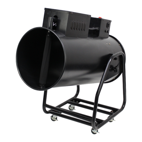
Safety advice WARNING: CAUTION! FOR YOUR OWN SAFETY, PLEASE READ THIS USER TAKE CARE USING MANUAL CAREFULLY BEFORE YOUR INITIAL START-UP! THIS EQUIPMENT! • Before your initial start-up, please make sure that HIGH VOLTAGE-RISK there is no damage caused during transportation. OF ELECTRIC SHOCK!! • Should there be any damage, consult your dealer and do not use the equipment. • Please note that damages caused by user modifications • To maintain the equipment in good working condition to this equipment are not subject to warranty. and to ensure safe operation, it is necessary for the user to follow the safety instructions and warning notes written in this manual. - Page 3 Product overview & technical specifications Avalanche Snow Machine Designed for large events, the Avalanche from Equinox utilises a large, high output fan to project the snow flakes up to 10 metres into the air. Adjustable output, controllable from either the supplied wired remote control or on board DMX. Supplied complete with custom designed flight case for protection during transportation. The robust steel chassis with built in tilt mechanism allows the user to direct the output as required. • Output volume: 150m per minute (full on) • Fluid consumption: 540ml/min at 100% (approx.) • Control: Wired remote control and DMX Specifications Power consumption 1500W (max.) Power supply 240V, 50Hz Unit dimensions 830 x 470 x 820mm Unit weight 28.8kg Flight case dimensions 1010 x 880 x 520mm with wheels Flight case dimensions 890 x 880 x 520mm without wheels Flight case weight 30kg Handheld Total weight 58.8kg Remote Control Flightcase included included Order code...
-
Page 4: Technical Specifications
Technical specifications POWER INPUT: 240V~50Hz RESETTABLE FUSE DMX OUTPUT DMX INPUT REMOTE CONTROL DIPSWITCHES POWER INPUT: 240V~50Hz DMX OUTPUT DMX INPUT RESETTABLE REMOTE CONTROL FUSE DIPSWITCHES In the box: 1 x fixture, 1 x remote 01 - Fluid pipe and 03 - Bracket 07 - Remote control 09 - Resettable fuse control, 1 x flightcase intake unit socket 15A 250V... -
Page 5: Danger Of Fire
Operating instructions Operation: Place the unit on a level surface. Always disconnect it from the mains supply before filling as fluid could be spilled. Always fill the tank away from the unit to prevent fluid getting inside the main housing. If fluid should get inside the main housing, disconnect the unit from the mains immediately and consult a technician. Installation: Install the unit in a well-ventilated area. Use in an insufficiently ventilated room can lead to the condensation of the snow fluid. The resulting slippery surface can cause accidents. Keep a minimum distance of 1m around the unit. Furthermore do not orientate the output aperture directly in the direction of the audience’s eyes. In order to create the best effect, there should be a distance between the unit and the audience of at least 5m. Only install the snow machine on fire resistant, scratch resistant and water resistant surfaces. This unit is constructed for a free standing installation only. The unit can be used whilst in the base of the flightcase with the lid removed. Make sure all brakes are applied to the flightcase and the unit. The operator must always make sure that the safety-relating and machine-technical installations are approved by an expert before operation for the first time and after any further changes are made. The operator has to make sure that the safety-relating and machine-technical installations are approved by a qualified person once a year. Important: Please make sure you connect a substantial fluid source as 5 litres of fluid will only produce a maximum of 10 minutes full on snow output. Do not allow the fluid source to run dry. To prevent the unit from overheating it is advised after 20 minutes on continuous operation you stop the unit outputting snow for approx. 10 minutes so the unit can cool down. At the end of each operation water must be run through the pump to prevent seizure. DANGER OF FIRE! When installing the unit, make sure there is no highly flammable material (decoration articles etc) within a minimum distance of 1m... - Page 6 Operating instructions Cleaning and maintenance: We recommend a frequent cleaning of the unit. Please use a soft lint-free and moistened cloth. Never use alcohol or solvents! The fluids we recommend are non-hazardous to the environment and can be disposed of via the sewage system. There are no serviceable parts inside this unit. Maintenance and service operations are only to be carried out by authorised dealers. Breaker reset: In the event of a power failure, please reset the 15A breaker located below the PowerCON input. If the breaker trips after it has been reset, this usually indicates a component fault. Disconnect the unit from the mains power supply and contact your local dealer for more information. Should you need any spare parts, only use genuine parts. If defective, please dispose of the unusable unit in accordance with the current legal regulations. Should you have any further questions, please contact your dealer. www.prolight.co.uk Avalanche Snow Machine User Manual...
-
Page 7: Operation
Operating instructions Operation: Connect the unit to a mains power supply via a powerCON cable. Then turn the power switch to ON, the red indication light on the power switch will illuminate. For manual control simply connect the remote control provided and follow the remote control operation instructions below. Remote control operation: 01 - Output volume Ensure the remote control switch is off and the output 02 - In use indicator volume rotary knob is turned counter-clockwise until it 03 - Power indicator stops. 04 - ON/OFF switch Connect the handheld remote control to the main unit via the remote control socket. Once the remote is connected the red power indicator will illuminate. Press the switch on the handheld remote control to ON, the green in use indicator will illuminate. When you are ready to disperse snow, turn the output volume rotary knob clockwise to the desired output. To stop the dispersion of snow turn the output volume rotary knob counter-clockwise until it stops. Care should be taken to ensure the fluid level is maintained and the unit is not allowed to run dry of fluid. Isolate from the mains supply before disconnecting or reconnecting the fluid source. www.prolight.co.uk Avalanche Snow Machine User Manual... - Page 8 Operating instructions DMX mode: Operating in a DMX control mode environment gives the user the greatest flexibility when it comes to customising, controlling or creating a show. DMX addressing is facilitated via the dipswitches on the top of the unit. Addressing Each device occupies 1 channel. To ensure that the control signals are properly directed to each device the fixture requires addressing. This needs to be changed for every fixture by changing the dipswitches as set out in the table below. The starting address is defined as the first channel from which the device will respond to the controller. Please make sure that you do not have any overlapping channels in order to control each fixture correctly and independently from any other fixture on the DMX data link. If two, three, or more devices are addressed similarly, they will work similarly. Occupation of the dipswitches: Controlling After having addressed all Dipswitch number devices, you may now start DMX starting address 128 256 operating these via your controller. Fixture 1 - Channel 1 1 channel mode Fixture 2 - Channel 2 Channel Value Function 000-255 Snow output Fixture 3 - Channel 3 (0-100%) Fixture 4 - Channel 4 Fixture 5 - Channel 5 www.prolight.co.uk Avalanche Snow Machine User Manual...
- Page 9 Operating instructions DMX dipswitch quick reference chart DMX DIPSWITCH SET 0 = OFF 1 = ON 128 160 192 224 256 288 320 352 384 416 448 480 129 161 193 225 257 289 321 353 385 417 449 481 130 162 194 226 258 290 322 354 386 418 450 482 131 163 195 227 259 291 323 355 387 419 451 483 100 132 164 196 228 260 292 324 356 388 420 452 484...
-
Page 10: Dmx Setup
DMX setup Setting the DMX address: The DMX mode enables the use of a universal DMX controller. Each fixture requires a “start address” from 1- 511. A fixture requiring one or more channels for control begins to read the data on the channel indicated by the start address. For example, a fixture that occupies or uses 7 channels of DMX and was addressed to start on DMX channel 100, would read data from channels: 100,101,102,103,104,105 and 106. Choose a start address so that the channels used do not overlap. E.g. the next unit in the chain starts at 107. DMX 512: DMX (Digital Multiplex) is a universal protocol used as a form of communication between intelligent fixtures and controllers. A DMX controller sends DMX data instructions form the controller to the fixture. DMX data is sent as serial data that travels from fixture to fixture via the DATA “IN” and DATA “OUT” XLR terminals located on all DMX fixtures (most controllers only have a data “out” terminal). DMX linking: DMX is a language allowing all makes and models of different manufactures to be linked together and operate from a single controller, as long as all fixtures and the controller are DMX compliant. To ensure proper DMX data transmission, when using several DMX fixtures try to use the shortest cable path possible. The order in which fixtures are connected in a DMX line does not influence the DMX addressing. For example; a fixture assigned to a DMX address of 1 may be placed anywhere in a DMX line, at the beginning, at the end, or anywhere in the middle. When a fixture is assigned a DMX address of 1, the DMX controller knows to send DATA assigned to address 1 to that unit, no matter where it is located in the DMX chain. DATA cable (DMX cable) requirements (for DMX operation): This fixture can be controlled via DMX-512 protocol. The DMX address is set on the back of the unit. Your unit and your DMX controller require a standard 3-pin XLR connector for data input/output, see image below. Further DMX cables can be purchased from all good sound and lighting suppliers or Pro Light Concepts dealers. -
Page 11: Line Termination
DMX setup Notice: Be sure to follow the diagrams below when making your own cables. Do not connect the cables shield conductor to the ground lug or allow the shield conductor to come in contact with the XLRs outer casing. Grounding the shield could cause a short circuit and erratic behaviour. Special note: Line termination: When longer runs of cable are used, Termination reduces signal transmission you may need to use a terminator on problems and interference. It is always advisable to connect a DMX terminal, the last unit to avoid erratic behaviour. (resistance 120 Ohm 1/4 W) between pin 2 Using a cable terminator will decrease (DMX-) and pin 3 (DMX+) of the last fixture. the possibilities of erratic behaviour. (3-pin - Order ref: CABL90, 5-pin - Order ref: CABL89) 5-pin XLR DMX connectors: Some manufactures use 5-pin XLR connectors for data transmission in place of 3-pin. 5-pin XLR fixtures may be implemented in a 3-pin XLR DMX line. When inserting standard 5-pin XLR connectors in to a 3-pin line a cable adaptor must be used. The diagram below details the correct cable conversion. -
Page 12: Weee Notice
WEEE notice Correct Disposal of this Product (Waste Electrical & Electronic Equipment) (Applicable in the European Union and other European countries with separate collection systems) This marking shown on the product or its literature, indicates that it should not be disposed of with other household wastes at the end of its working life. To prevent possible harm to the environment or human health from uncontrolled waste disposal, please separate this from other types of wastes and recycle it responsibly to promote the sustainable reuse of material resources. Household users should contact either the retailer where they purchased this product, or their local government office, for details of where and how they can take this item for environmentally safe recycling. Business users should contact their supplier and check the terms and conditions of the purchase contract. This product should not be mixed with other commercial wastes for disposal. www.prolight.co.uk Avalanche Snow Machine User Manual...
Need help?
Do you have a question about the Avalanche EQLED358 and is the answer not in the manual?
Questions and answers