Panduit Smartzone G5 User Manual
Intelligent network controller, pdu
Hide thumbs
Also See for Smartzone G5:
- User manual (152 pages) ,
- Installation manual (20 pages) ,
- Manual (2 pages)
Table of Contents
Advertisement
Advertisement
Table of Contents

Related Manuals for Panduit Smartzone G5


Summary of Contents for Panduit Smartzone G5
- Page 1 G5 PDU User Manual...
-
Page 2: Table Of Contents
Supported Commands ................... 25 Connecting to the CLI through the serial interface ............. 26 Section 5 – Local Display ....................28 OLED Display ......................28 Menu Mode ......................29 OLED Menu Structure ....................30 Main Menu Selections .................... 31 SMARTZONE G5 USER MANUAL... - Page 3 Configuring User for Local Rack Access..............81 Warranty and Regulatory Information................83 Warranty Information ....................83 Regulatory Information ....................83 Support and Other Resources ..................84 Accessing Panduit Support ..................84 Acronyms and Abbreviations ..................85 Documentation Feedback ..................... 88 SMARTZONE G5 USER MANUAL...
- Page 4 Upgrade Configuration with Bootloader Mode ............105 Appendix E: PDU Alarms .................... 106 Trap Codes assigned to Alarms List ................ 108 Appendix F: Horizontal Intelligent Network Controller Replacement ......113 Appendix GF: Vertical Intelligent Network Controller Replace or Rotate 180° .... 116 SMARTZONE G5 USER MANUAL...
-
Page 5: Figures
Figure 32: Device Submenu ..................33 Figure 33: Screen Submenu ..................34 Figure 34: Language Submenu ..................35 Figure 35: USB Submenu ..................... 36 Figure 36: Units Submenu ..................... 37 Figure 37: Alarms Menu ....................38 SMARTZONE G5 USER MANUAL... - Page 6 Figure 69: Remove Intelligent Network Controller from PDU ........114 Figure 70: Inserting New Intelligent Network Controller ..........115 Figure 71: Removing Top and Bottom Screw from Intelligent Network Controller ..116 Figure 72: Disconnecting and Reconnecting the Intelligent Network Controller ..117 SMARTZONE G5 USER MANUAL...
-
Page 7: Section 1 - System Overview
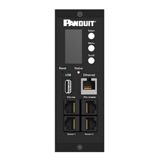
Section 1 – System Overview Intelligent Network Controller The Panduit G5 Intelligent PDUs have an integral, hot swappable Intelligent Network Controller. The Intelligent Network Controller contains an OLED display, control buttons, USB Interface, Serial and Sensor ports, and a recessed Reset Button. -
Page 8: Connecting The Pdu To A Computer Serial Port
2. Using a CLI command to enable DHCP or set a static IP. 3. Verify access to the Web interface. The Ethernet LED on the PDU front panel provides communication status by color and display activity. The recessed Reset button restarts the PDU (see Figure 2 below). SMARTZONE G5 USER MANUAL... -
Page 9: Setup Serial Communication
Users can connect serially using the optional RJ45-DB9 cable Panduit p/n: MA001 (or make your own cable by creating a unique pinout as described below in the “Serial Cable Pinout to Create Your Own Cable” in Section 4). -
Page 10: Figure 3: Port Setup Settings
• Username: admin • Password: 12345678 (or your new password) 6. The “Panduit>” prompt appears after you have logged in, ready to enter the CLI command. 7. To configure network settings, enter the appropriate “net” command and press Enter. - Page 11 9. To set a static IPv4 configuration, run: • net tcpip static x.x.x.x (ipaddress) x.x.x.x (netmask) x.x.x.x (gateway) • Example: net tcpip static 192.168.1.100 255.255.255.0 192.168.1.1 • Enter Y to confirm and the PDU’s Intelligent Network Controller will reboot. SMARTZONE G5 USER MANUAL...
-
Page 12: Section 2 - Web Graphical User Interface (Gui) Configuration
Open a supported web browser and enter the IP address of the PDU. If username and password were configured during the Network Configuration Setup: enter the username and password in the appropriate fields. Press Login or Enter. SMARTZONE G5 USER MANUAL... -
Page 13: Introduction To The Web Gui
If username and password were NOT configured during the Network Configuration Setup, use the default username: admin and password: 12345678. For security purposes, change the password upon login. Introduction to the Web GUI Login Page Figure 4: Login Page SMARTZONE G5 USER MANUAL... -
Page 14: Figure 5: Landing Page/Dashboard
This icon lets you select a Language. There are seven languages available to choose from: English, Chinese, French, Italian, German, Spanish, Korean and Japanese. This icon provides the logs of the PDU which can be viewed and downloaded. SMARTZONE G5 USER MANUAL... - Page 15 You also can also click user guide and license to ask for help. This icon shows who is logged in (user or admin). Account passwords can be changed, and user accounts managed through this page. SMARTZONE G5 USER MANUAL...
-
Page 16: Menu Dropdowns
Menu Dropdowns Overview Alarms Help Language Logs Settings Admin SMARTZONE G5 USER MANUAL... -
Page 17: Introduction To The Dashboard
Introduction to the Dashboard Power Summary Page Figure 6: Power Summary Page Outlet Monitoring Page Figure 7: Outlet Monitoring Page SMARTZONE G5 USER MANUAL... -
Page 18: Figure 8: Environmental Page
Environmental Page Figure 8: Environmental Page Security Page Figure 9: Security Page SMARTZONE G5 USER MANUAL... -
Page 19: Section 3 - Simple Network Management Protocol (Snmp)
1. Access the Web interface and login. 2. Under SNMP Managers, select SNMP General (or type SNMP in the search). The SNMP General page displays. Figure 10: SNMP Management 3. The SNMP General includes SNMP Access and Version. SMARTZONE G5 USER MANUAL... -
Page 20: Figure 15: Snmp General
Figure 11: SNMP General Setup SNMP Port 1. Access the Web interface and login. 2. Under SNMP Managers, select SNMP Port. The SNMP Port page displays. SMARTZONE G5 USER MANUAL... -
Page 21: Figure 16: Snmp Port
Figure 12: SNMP Port 3. Setup SNMP Port and SNMP Trap Port Figure 13: Setup SNMP Port and Trap Port SMARTZONE G5 USER MANUAL... -
Page 22: Figure 18: Define Snmp V1/V2C User
3. In the SNMP V1/V2c panel, select the SNMP V1/V2c manager to configure. Select the pencil icon in the last column. Figure 14: Define SNMP V1/V2c User 4. The Edit panel pop up displaying the configurable options. Figure 15: Edit V1/2c Manager SMARTZONE G5 USER MANUAL... -
Page 23: Configuring Users For Snmp V3 Communications
3. In the SNMP V3 panel, select the SNMP V3 manager to configure. Select the pencil icon in the last column. Figure 16: SNMP V3 Manager 4. The Edit panel pop up displaying the configurable options. SMARTZONE G5 USER MANUAL... -
Page 24: Figure 21: Snmp V3 Edit
• NoAuthNoPriv: No authentication and no privacy. This is the default. • AuthNoPriv: Authentication and no privacy. • AuthPriv: Authentication and privacy. 7. Enter a new unique password to be used for authentication 8. Select the desired authentication algorithm. • MD5 • SHA SMARTZONE G5 USER MANUAL... -
Page 25: Configuring Snmp Traps
IP Address is the address to which traps are sent by the SNMP system agent. b. Port is the communication port number. c. Community is the group representing the PDU and SNMP management stations. 5. Select OK to save and exit. SMARTZONE G5 USER MANUAL... -
Page 26: Section 4 - Connecting To Cli Connection
([ ]). For data of type array, the 'x' character as index of array in command input syntax means all indexes. You must be logged into the PDU before commands can be sent. See Appendix A for a list of all CLI commands. SMARTZONE G5 USER MANUAL... -
Page 27: Connecting To The Cli Through The Serial Interface
“Serial+RS485-1” on the front panel of your PDU model. Connect the DB9 end of the cable to the serial connector on the computer. Logging in with HyperTerminal To login through HyperTerminal, set the COM settings to the following parameters: • Bits per second: 115200 SMARTZONE G5 USER MANUAL... -
Page 28: Figure 25: Serial Cable Pinout
5. Enter your Username. Press Enter. 6. Enter your password. Press Enter. 7. You are now logged into the SSH. Refer to the CLI Commands table below for available commands. NOTE: SSH connection is not available when serial connection is enabled. SMARTZONE G5 USER MANUAL... -
Page 29: Section 5 - Local Display
OLED setting. The display can be rotated 180°. The PDU has a three-button, graphical OLED panel (see Figure 4). Use the buttons to change the screen display and retrieve specific data. Figure 20: the OLED Display Orientation SMARTZONE G5 USER MANUAL... -
Page 30: Menu Mode
Opens the selected menu. display screen before entering the screensaver mode. LED Unit Status The LED will change colors depending on the state of the PDU. LED State Description Solid Green Normal Operation Solid Red Critical or Warning Alarm SMARTZONE G5 USER MANUAL... -
Page 31: Oled Menu Structure
LED State Description Flashing Orange No network connection OLED Menu Structure Figure 21: OLED Menu Structure SMARTZONE G5 USER MANUAL... -
Page 32: Main Menu Selections
Network. Press Select to enter the Network Submenu. Scroll down to highlight the selected option from the menu. Press Select to display the screens that display the IP address. Press Menu to return to the previous menu. SMARTZONE G5 USER MANUAL... -
Page 33: Figure 31: Network Submenu
Firmware version. On the Setup menu, scroll down to highlight Device submenu. Press Select to enter the Device Submenu. Scroll down to the item you wish to display and press Select. Press Menu to return to the previous menu. SMARTZONE G5 USER MANUAL... -
Page 34: Figure 32: Device Submenu
The Screen submenu allows you to customize settings for Contrast, Rotate, and Always on. On the Setup menu, scroll down to highlight Screen. Press Select to select the submenu. Press Menu to return to the previous menu. SMARTZONE G5 USER MANUAL... -
Page 35: Figure 33: Screen Submenu
Setup menu, scroll down to highlight Lang. Press Select to display the screens to select the submenu. After you select the values, press Select to set the values as displayed on the screen. Press Menu to return to the previous menu. SMARTZONE G5 USER MANUAL... -
Page 36: Figure 34: Language Submenu
Note 2: If you are in USB mode and you want to exit USB mode, you must remove the USB drive before existing USB mode. Otherwise, the PDU will reset and re-enter USB mode. SMARTZONE G5 USER MANUAL... -
Page 37: Figure 35: Usb Submenu
Figure 28: USB Submenu SMARTZONE G5 USER MANUAL... -
Page 38: Figure 36: Units Submenu
The Alarms menu displays active alarms for the PDU. On the Main Menu, scroll down to highlight Alarms. Press Select to display the Alarm Screen. When you finish your review, press Menu to return to the main menu. SMARTZONE G5 USER MANUAL... -
Page 39: Figure 37: Alarms Menu
The Power menu manages device, phase, breaker and outlet. On the Main Menu, scroll down to highlight Power. Press Select. Scroll down to select a submenu and press Select to display the submenu options. Press Menu to return to the previous menu. Figure 31: Power Menu SMARTZONE G5 USER MANUAL... - Page 40 Phase. Press Select to display the screens to set the values for the submenu. After you select the phase, press Select to display the values for that phase on the screen. Press Menu to return to the previous menu. SMARTZONE G5 USER MANUAL...
- Page 41 The Breaker submenu is to display power values for the breakers. Press Select to display the values of the first breaker. To go to the next breaker, Select next. Press Menu to return to the previous menu. SMARTZONE G5 USER MANUAL...
- Page 42 On the Power menu, scroll down to highlight Outlet. Press Select to display values for the first outlet. To go to the next outlet, Select next. Press Menu to return to the previous menu. SMARTZONE G5 USER MANUAL...
-
Page 43: Sensors Menu
The Sensor menu is to display temperature, humidity, door switch, fluid leak etc. On the Main Menu, scroll down to highlight Sensor. Press Select. This will display the sensor data for the first sensor. To go to the next sensor, Select next. Press Menu to return to the previous menu. SMARTZONE G5 USER MANUAL... - Page 44 Figure 36: Sensors NOTE: Maximum of 8 sensors are configured per PDU. SMARTZONE G5 USER MANUAL...
-
Page 45: Section 6 - User Access
At initial login, you are required to change the default password: 1. Enter the current password and new password twice to confirm. By default, passwords must be between 8 and 32 characters. Figure 37: Changing Your Password 2. Click Change Password to complete the password change. SMARTZONE G5 USER MANUAL... - Page 46 Figure 38: After Login 2. The Change User Password window opens. Figure 39: Change User Password 3. Enter the old password and then new password twice to confirm. By default, passwords must be between 8 and 32 characters. SMARTZONE G5 USER MANUAL...
-
Page 47: Access Types
• Administrator Privileges • Read Only The Panduit PDU comes with a standard Administrator Privileges profile and a standard Read Only profile. The “Admin Role” is typically the system administrator and has the Administrator Privileges with full operating permissions. By default, the User Role is a Read Only profile. - Page 48 8-32 characters in length, and have at least one numeric character, and at least one special character. 4. Use the Roles tab to set full or read only privileges. 5. Select “Add User” to save the new user profile. Modify user profile: 1. Go to User Administration>Users. SMARTZONE G5 USER MANUAL...
-
Page 49: Setting Up The System For Radius Authentication
2. Select the red X next to user name. Setting up the system for Radius Authentication 1. Go to User Settings > in the admin menu. Figure 41: User Settings 2. Go to Radius Configuration and click the edit pencil. SMARTZONE G5 USER MANUAL... -
Page 50: Configuring The System With Ldap Server Settings
2. Select the LDAP Enable checkbox. 3. Use the drop-down menu to choose the Type of LDAP Server. Choose Microsoft Active Directory. 4. Enter an IP Address of the domain controller/Active Directory (AD) Server. i.e.: 192.168.1.101 (example) SMARTZONE G5 USER MANUAL... - Page 51 9. In the Login Name Attribute field, enter sAMAccountName (typically). 10. In the User Entry Object Class field, enter person. With these LDAP settings configured, the Bind is complete (see screen shot). Figure 43: LDAP Configuration SMARTZONE G5 USER MANUAL...
- Page 52 LDAP authentication is ready to use. To test this, just click save, then click on “LDAP Configuration” again and type an Active Directory user name/password into the test box. Click Test LDAP Configuration. If a box pops up with all green “SUCCEEDED” (no X’s), the LDAP is successfully configured. SMARTZONE G5 USER MANUAL...
- Page 53 Figure 45: Test LDAP Configuration Note: Be sure to login without a domain name. SMARTZONE G5 USER MANUAL...
-
Page 54: Section 7 - Daisy Chain Configuration
RNA allows for secure access of PDU data and statistics on 2 separate, private networks. RNA must be used with a redundant power delivery design including 2 rack PDUs for each IT rack. PDUs used in RNA applications must be the same SKU/Part Number. SMARTZONE G5 USER MANUAL... -
Page 55: Rna Setup
3. Enter Y to confirm reboot. 4. After reboot, the PDU will be setup to RNA Mode. 5. Repeat this process for the second PDU. To Connect the PDUs for RNA Setup After the PDUs are configured for RNA: SMARTZONE G5 USER MANUAL... - Page 56 6. To enable this account, login to the CLI with admin credentials. 7. Enter the command ‘dev daisy rna init’. 8. The following message will appear to confirm the landlord account is enabled: SUCCESS. 9. RNA is now configured and enabled. SMARTZONE G5 USER MANUAL...
-
Page 57: Section 8- Web Gui Configuration
• Enter the IP address of the primary NTP server in the First Time Server field. • Enter the IP address of a secondary NTP server. Optional. 5. Select OK to save the changes. G5 iPDU Outlet Power Sequence Setup 1. From the PDU GUI Home menu select Control & Manage. SMARTZONE G5 USER MANUAL... - Page 58 Figure 46: Control & Manage PDU 1. Select Outlet Control Enabled Figure 47: Outlet Control Enabled SMARTZONE G5 USER MANUAL...
- Page 59 2. For each Outlet select the Edit pencil. Figure 48: Edit Outlets 3. In the Edit Outlet window enter the On-Delay time (0-7200 seconds) then select Save. SMARTZONE G5 USER MANUAL...
- Page 60 Figure 49: One-Delay Time 4. Your Outlet Power Sequence has been set. Figure 50: Saved Sequence SMARTZONE G5 USER MANUAL...
-
Page 61: Outlet Power Management
4. Press Enter. Setting the Outlet Default State Setting the Outlet Default State on Panduit G5 iPDUs with outlet level control allows the user to determine the initial power status of an individual outlet upon PDU power up. 1. Expand the Outlet Information folder from the Control & Manage tab. -
Page 62: Setting Metering Thresholds
The G5 iPDU will send alert notifications when a power threshold wattage crosses above or below the settings you specify in the Power Threshold configuration: 1. Go to the Thresholds > Input Page. 2. Click the Pencil for the Power Threshold to update. SMARTZONE G5 USER MANUAL... - Page 63 The Reset threshold is the number of watts the reading needs to fall below the threshold setting for the condition to be cleared. For example, the current critical threshold for the input phase is set to 19 SMARTZONE G5 USER MANUAL...
- Page 64 The G5 iPDU will send alert notifications when an energy threshold kilowattage crosses above or below the settings you specify in the Energy Threshold configuration: 1. Go to the Thresholds > Energy Page. 2. Click the Pencil for the Energy Threshold to update. SMARTZONE G5 USER MANUAL...
- Page 65 4. Repeat steps 1 - 3 for all PDUs. Phase Current Alarm Threshold The G5 iPDU will send alert notifications when a phase current alarm amp crosses SMARTZONE G5 USER MANUAL...
- Page 66 2. Click the Pencil for the Phase Current Alarm to update. Figure 53 - Phase Current Alarm 3. Select and enter the appropriate thresholds in amps and then click Save. • Lower Critical (A) • Lower Warning (A) • Upper Warning (A) SMARTZONE G5 USER MANUAL...
- Page 67 The G5 iPDU will send alert notifications when a phase voltage crosses above or below the settings you specify in the Phase Voltage Alarm configuration: 1. Go to the Thresholds > Phase Page. 2. Click the Pencil for the Phase Voltage to update. SMARTZONE G5 USER MANUAL...
- Page 68 • Lower Warning (V) • Upper Warning (V) • Upper Critical (V) • Reset Threshold (V) The Reset threshold is the number of amps the reading needs to fall below the threshold setting for the condition to be cleared. SMARTZONE G5 USER MANUAL...
- Page 69 The G5 iPDU will send alert notifications when a circuit breaker amperage crosses above or below the settings you specify in the Circuit Breaker Alarms configuration: 1. Go to the Thresholds > Circuit Breaker Page. 2. Click the Pencil for the Circuit Break to update. SMARTZONE G5 USER MANUAL...
- Page 70 The Reset threshold is the number of amps the reading needs to fall below the threshold setting for the condition to be cleared. For example, the current critical threshold for the input phase is set to 19 SMARTZONE G5 USER MANUAL...
- Page 71 The G5 iPDU will send alert notifications when a outlet amperage crosses above or below the settings you specify in the Outlet Alarms configuration: 1. Go to the Thresholds > Outlet Page. 2. Click the Pencil for the Outlet to update. SMARTZONE G5 USER MANUAL...
- Page 72 For example, the current critical threshold for the input phase is set to 19 watts (W). The current draw rises to 20W, triggering a Current Critical SMARTZONE G5 USER MANUAL...
- Page 73 This prevents several threshold alerts from being generated if the measurements return to normal immediately after rising above an upper threshold or dropping below a lower threshold. Repeat steps 1 - 3 for all outlets. SMARTZONE G5 USER MANUAL...
-
Page 74: Section 9 - Connecting And Configuring Optional Hardware
Hardware Accessory Hardware Overview All Panduit SmartZone G5 Intelligent PDUs can monitor environmental conditions of a rack with the addition of optional SmartZone G5 environmental sensors. Conditions such as temperature, humidity, leak detection, and intrusion can be monitored with the sensors. - Page 75 The optional environmental sensors can be installed before or after completing the PDU installation, startup, and can be installed without turning off power to the PDU or the devices connected. Panduit G5 Monitored Input, Monitored Switched, Monitored per Outlet, and Monitored & Switched per Outlet PDUs are designed to collect a maximum of eight environmental sensor measurements per PDU.
- Page 76 All Panduit G5 PDUs have two physical sensor ports, and each PDU can collect a total of eight sensor measurements (or readings). For example, if a PDU has a Door Sensor and an Environmental Three Temperature + Humidity Sensor connected, both physical sensor ports are used with a total of five sensor measurements recorded.
-
Page 77: Configuring Environmental Sensors
4. Select Edit button to configure the desired sensors. 5. In the Edit dialog box, type value of up critical, up warning, low warning, and low critical. 6. Select Save to exit the sensor setup. Repeat this process for additional sensors. SMARTZONE G5 USER MANUAL... -
Page 78: Section 10 - Rack Access Control
Figure below for a diagram of a typical Rack Access Control setup. Figure 57 - Rack Access Control Note: For details on the RFID cards supported, please see the Specification Sheets for the respective Panduit G5 Electronic Swinghandles. SMARTZONE G5 USER MANUAL... -
Page 79: Configuring Rack Access Control
2. Go to the Gear icon > Rack Access Control 3. The Actions Menu on the right side of the page will allow the user to add a new Electronic handle, Remote Control the handle, or Configure the AutoLock setting of the handle. SMARTZONE G5 USER MANUAL... - Page 80 (top portion of the Swinghandle) and select the Event Log option within the G5 iPDU. Note: In the above example, the card ID is 289537. 5. Using the above card ID, you can add an authorized user to the iPDU. SMARTZONE G5 USER MANUAL...
- Page 81 Note: The Hot Aisle or Cold Aisle is selected at the Access Hub (ACB01) through a DIP Switch. Not as a pull-down in the Web Interface. 6. The remote control allows you to lock or unlock the Electronic Handle. Figure 60 - Remote Control SMARTZONE G5 USER MANUAL...
-
Page 82: Configuring User For Local Rack Access
(cold aisle) and one for the back (hot aisle). • If a user requires access to both the hot and cold aisles, you will need to add two entries in the table. One for the front door and one for the back door. SMARTZONE G5 USER MANUAL... - Page 83 Figure 22 - Rack Access Setting 3. Select Create. SMARTZONE G5 USER MANUAL...
-
Page 84: Warranty And Regulatory Information
Warranty and Regulatory Information Warranty Information (http://www.Panduit.com) Regulatory Information Safety and regulatory compliance For important safety, environmental, and regulatory information, see Safety and Compliance Information at the Panduit website (http://www.Panduit.com) SMARTZONE G5 USER MANUAL... -
Page 85: Support And Other Resources
Support and Other Resources Accessing Panduit Support • For live assistance, go to the Panduit.com website • To access documentation and support services, go to the Panduit website. SMARTZONE G5 USER MANUAL... -
Page 86: Acronyms And Abbreviations
Acronyms and Abbreviations Amps/Amperes Alternating Current Advanced Encryption Standard Command Line Interface Data Encryption Standard DHCP Dynamic Host Configuration Protocol Gigabyte Graphical User Interface Intelligent Network Controller Internet Protocol iPDU Intelligent Power Distribution Unit SMARTZONE G5 USER MANUAL... - Page 87 Kilo-Volt-Ampere Kilowatts Kilowatt Hour Local Area Network Liquid-Crystal Display LDAP Lightweight Directory Access Protocol OLED Organic Light-Emitting Diode Power Distribution Unit Quad-Network Interface Redundant Network Interface Secure Hash Algorithms SNMP Simple Network Management Protocol SMARTZONE G5 USER MANUAL...
- Page 88 TCP/IP Transmission Control Protocol/Internet Protocol Universal Serial Bus Volts Watts SMARTZONE G5 USER MANUAL...
-
Page 89: Documentation Feedback
Documentation Feedback Panduit is committed to providing documentation that meets your needs. To help us improve the documentation, send any errors, suggestions, or comments to Documentation Feedback (CS@Panduit.com). When submitting your feedback, include the document title, part number, edition, and publication date located on the front cover of the document. -
Page 90: Appendix A: Cli Commands
Panduit>sys time time. Panduit>sys time 14:35:34 sys ntp <IP Address> Synchronize system date >sys ntp 69.25.96.13 and time, with ntp server NOTE: IP Address must be a you set. valid ntp, server address otherwise, executes, failed SMARTZONE G5 USER MANUAL... - Page 91 NOTE 2: If in daisy chain configuration, master will also upgrade its all slave’s firmware. sys upd boot Update system’s Panduit>sys upd boot bootloader. SUCCESS system will enter upgrade mode after reboot System Reboot now, Are you sure? (Y/N):Y SMARTZONE G5 USER MANUAL...
- Page 92 Delete data log file. Panduit>sys log del data, SUCCESS Panduit> Network Commands Command Description Example net ssh [on/off] Query or on/off SSH. Panduit>net ssh SUCCESS, SSH Port: 22 SSH Server is running SMARTZONE G5 USER MANUAL...
- Page 93 Panduit>net tcpip dhcp SUCCESS Network is reconfigured, Please reboot to validate System Reboot now, Are you sure? (Y/N): Y net tcpip <static ip, mask, Set static IP, mask and Panduit>net tcpip static gateway> gateway. 192.168.30.39 255.255.255.0 SMARTZONE G5 USER MANUAL...
- Page 94 “Maximum number of failed logins”. Use this command to unlock it. Device Commands Command Description Example dev usb [on|off] Query or on/off USB. Panduit>dev usb Panduit>dev usb off Panduit>dev usb on SMARTZONE G5 USER MANUAL...
- Page 95 1; if in daisy chain, the master's PDUID is 1, others is ,2,3, dev outlet <PDUID> Query or set specified Panduit> dev outlet 1 1 off <outlet index> [on|off] PDUID and outlet-index's SUCCESS outlet status. SMARTZONE G5 USER MANUAL...
- Page 96 SKU: P9S20A , , , , unit’s electric information. Serial: , , , , , FuncType: PDU Monitored Rating :220-240V, 16A, 3.5-3.8kVA, 50/60Hz Mac :C8:45:44:66:2B:26 Tcpip :192:168:30:38 Panduit>pwr unit 1 SUCCESS PDU UNIT 1 power Feature SMARTZONE G5 USER MANUAL...
- Page 97 <idx> Query specified outlet’s Panduit> pwr outlet 1 electric information. SUCCESS PDU OUTLET 1 power Feature voltage: 0V current : 0.0A active power: 0W apparent power: 0W NOTE: For Monitored PDUs, this command is invalid. SMARTZONE G5 USER MANUAL...
-
Page 98: Appendix B: Sensor Configuration
The door switch can be configured to alert when the door is opened, alert when the door is closed, or the alerts can be disabled. Note: The Door Switch Sensor is only designed to connect to a Panduit G5 iPDU. Connecting it to another device may result in damage. - Page 99 The Water - Rope Sensor is designed to provide early detection of fluid along the entire length of the sensor cable. The rope sensor’s alarm can be enabled or disabled. Note: The Water - Rope Sensor is designed to connect only to a Panduit G5 iPDU. Connecting it to another device may result in damage.
- Page 100 The spot sensor’s alarm can be enabled or disabled. Note: The Water - Spot Sensor is designed to connect only to a Panduit G5 iPDU. Connecting it to another device may result in damage. Temperature & Humidity Sensors Temperature and humidity sensors are designed to add comprehensive environmental monitoring to any Panduit G5 iPDU.
- Page 101 Note: It is recommended that the EC001, SmartZone G5 Three Temperature + Humidity Sensor, be plugged directly into the Panduit G5 iPDU. Note: The Temperature and Humidity sensors are only designed to connect to a Panduit G5 iPDU. Connecting it to another device may result in damage. SMARTZONE G5 USER MANUAL...
-
Page 102: Appendix C: Firmware Update Procedure
1. Open the User interface in a web browser by entering the PDU IP address. 2. Login to with Administration credentials. 3. Go to System Management >Update Firmware. 4. In the Firmware Update dialog box, browse to Panduit.FW firmware file. SMARTZONE G5 USER MANUAL... - Page 103 Figure 62: Upload Firmware NOTE: the firmware file must be named Panduit.FW. 5. Select Upload. The system will update the newest firmware to the Intelligent Network Controller. SMARTZONE G5 USER MANUAL...
-
Page 104: Ftps Method
1. Login to a FTPs program with a role with administration privileges. 2. Transfer the updated Panduit.fw file to the folder labeled fw. Close the FTPs. 3. Connect to the PDU via SSH using a program such as HyperTerm or PuTTY. -
Page 105: Bootloader Mode
Bootloader Mode 1. Go to www.Panduit.com and download the most recent Firmware version, ‘Panduit.bin’. Save this file to a USB drive. 2. Insert the USB drive into the USB port of the Intelligent Network Controller. -
Page 106: Appendix D: System Recovery
2. Select the Enable USB Access Checkbox. To upload configuration, you must: Copy conf.ini to USB. Insert USB to PDU. Enter USB mode in OLED device. Select Conf up. After the operation is completed, remove USB, and quit USB mode. SMARTZONE G5 USER MANUAL... -
Page 107: Appendix E: Pdu Alarms
Circuit Breaker Status ON Circuit Breaker Status OFF Outlet X Active Power Above upper critical Outlet X Active Power Above upper warning Outlet Outlet X Active Power Below lower warning Outlet X Active Power Below lower critical SMARTZONE G5 USER MANUAL... - Page 108 System Communication Lost Daisy Chain state changed USB Port User Activity User X Authentication failure User Activity User X User logged in User Activity User Activity User X Session timeout User Activity User X User blocked SMARTZONE G5 USER MANUAL...
-
Page 109: Trap Codes Assigned To Alarms List
The circuit breaker (1-12) current is ABOVE critical threshold value 27-38 The circuit breaker (1-12) current is BELOW critical threshold value 39-50 The circuit breaker (1-12) is in OFF state 51-98 The outlet (1-48) active power is ABOVE critical threshold value SMARTZONE G5 USER MANUAL... - Page 110 The phase (1-3) voltage is BELOW warning threshold value. 208-210 The phase (1-3) current is ABOVE warning threshold value. 211-213 The phase 1 current is BELOW warning threshold value. 214-225 The circuit breaker (1-12) current is ABOVE warning threshold value. SMARTZONE G5 USER MANUAL...
- Page 111 The outlet (1-48) DELAYED OFF occurred. 584-631 The outlet (1-48) IMMEDIATE REBOOT occurred. 632-679 The outlet (1-48) DELAYED REBOOT occurred. 680-727 The outlet (1-48) Cancel Pending Commands occurred. 728-735 The sensor (1-8) contact state is in cleared. Event log Cleared. SMARTZONE G5 USER MANUAL...
- Page 112 User xxx password changed. User password settings changed. User xxx added. User xxx deleted. User xxx modified. Smart Rack Access Door Opened Smart Rack Access Door Closed Smart Rack Access User Card Swiped Smart Rack Access Door Autolocked SMARTZONE G5 USER MANUAL...
- Page 113 The phase (1-3) voltage alarm cleared 774-776 The phase (1-3) current alarm cleared 777-788 The circuit breaker (1-12) current alarm cleared 789-836 The outlet (1-48) active power current alarm cleared. 837-844 The sensor (1-8) temperature/humidity alarm cleared. SMARTZONE G5 USER MANUAL...
-
Page 114: Appendix F: Horizontal Intelligent Network Controller Replacement
Appendix F: Horizontal Intelligent Network Controller Replacement 1. Unscrew the left and right captive nuts on the Intelligent Network Controller by turning them counter clockwise. Figure 64: Unscrew Intelligent Network Controller SMARTZONE G5 USER MANUAL... - Page 115 2. Pull out the Intelligent Network Controller from the PDU. Figure 65: Remove Intelligent Network Controller from PDU 3. Insert the new Intelligent Network Controller. SMARTZONE G5 USER MANUAL...
- Page 116 Figure 66: Inserting New Intelligent Network Controller 4. Align the Intelligent Network Controller and tighten the captive nuts by turning them clockwise. SMARTZONE G5 USER MANUAL...
-
Page 117: Appendix Gf: Vertical Intelligent Network Controller Replace Or Rotate 180
Figure 67: Removing Top and Bottom Screw from Intelligent Network Controller a. Controller may be rotated to accommodate overhead or underfloor power. If rotating controller; you do not need to disconnect the ribbon cable. Simply rotate and reinstall. SMARTZONE G5 USER MANUAL... - Page 118 Network Controller. Connect the ribbon cable to the new Intelligent Network Controller. Ribbon Cable Figure 68: Disconnecting and Reconnecting the Intelligent Network Controller 3. Replace and tighten the two (T10) screws on the Intelligent Network Controller. SMARTZONE G5 USER MANUAL...
Need help?
Do you have a question about the Smartzone G5 and is the answer not in the manual?
Questions and answers