Panduit Smartzone G5 User Manual
Intelligent pdu
Hide thumbs
Also See for Smartzone G5:
- User manual (118 pages) ,
- Installation manual (20 pages) ,
- Manual (2 pages)
Table of Contents
Advertisement
Quick Links
Advertisement
Table of Contents

Related Manuals for Panduit Smartzone G5


Summary of Contents for Panduit Smartzone G5
- Page 1 Intelligent PDU User Manual v4.2...
-
Page 2: Table Of Contents
Table of Contents Section 1 – System Overview ..................9 PDU Controller ......................9 Connecting the PDU via Ethernet Port ............... 9 Connecting the PDU to a Computer Serial Port ............10 Section 2 – Web Graphical User Interface (GUI) Configuration ........11 Internet Protocol (IP) Addressing ................ - Page 3 The Status LED ......................99 Setting Status LED State ..................100 Handle and Compatible Card Types ............... 100 Section 7 – SmartZone G5 Accessories ..............101 Hardware Overview ....................101 Configuring Temperature Scale ................103 Configuring Environmental Sensors ............... 103...
- Page 4 Appendix E: PDU Alarms ................... 120 Trap Codes assigned to Alarms List ............... 122 Appendix F: Panduit Network Controller Replace or Rotate 180° ....... 128 Appendix G: Direct connect to the PDU by Changing Your PC’s IP Address ..... 130 Appendix H: Command Line Interface (CLI) ...............
- Page 5 Appendix I: RADIUS Server Configuration ..............148 Appendix J: Panduit G5 Accessories ................. 150 Appendix K: Compliance Model Number Details ............151 Appendix L: JSON API Web Service ................152 INTELLIGENT PDU USER MANUAL...
- Page 6 Table of Figures Figure 1: Ethernet Port for Network Connection ............. 9 Figure 2: Status LED & Serial In Port Identified ............10 Figure 3: Changing Your Password ................12 Figure 4: After Login ....................12 Figure 5: Change User Password ................13 Figure 6: Change Password ..................
- Page 7 Figure 38: RADIUS Configuration ................50 Figure 39: LDAP Configuration ..................52 Figure 40: Enable Role Privileges ................53 Figure 41: Test LDAP Configuration ................54 Figure 42: SNMP Management ..................55 Figure 43: SNMP General .................... 56 Figure 44: SNMP Port ....................57 Figure 45: Setup SNMP Port and Trap Port ..............
- Page 8 Figure 76: Rack Access Settings Web GUI ..............93 Figure 77: Handle Settings Web GUI ................94 Figure 78: Remote Control ................... 96 Figure 79: Beacon......................97 Figure 80: Beacon Settings Web GUI ................98 Figure 81: Status LED Settings Web GUI ..............100 Figure 82: Sensor Ports for Vertical PDU ..............
-
Page 9: Section 1 - System Overview
Section 1 – System Overview PDU Controller All Panduit G5 Intelligent PDUs feature a Rotatable or Hot Swappable PDU Controller. This centralized piece of intelligent hardware receives an IP address, contains a Graphical Web Interface and is addressable over the network. -
Page 10: Connecting The Pdu To A Computer Serial Port
Connecting the PDU to a Computer Serial Port If unable to connect to network, you can change the network setting using the serial interface. To configure the network setting, perform the following steps: 1. Serial connect the PDU to a computer’s serial port. Set baud rate for a terminal emulation program. -
Page 11: Section 2 - Web Graphical User Interface (Gui) Configuration
Section 2 – Web Graphical User Interface (GUI) Configuration Internet Protocol (IP) Addressing After the PDU receives an IP address, login to the Web interface to configure the PDU and assign a static IP address (if desired). Connecting to the PDU 1. -
Page 12: Figure 3: Changing Your Password
Figure 3: Changing Your Password 2. Click Change Password to complete the password change. After the initial login, change the password by the following steps: Figure 4: After Login 2. The Change User Password window opens. INTELLIGENT PDU USER MANUAL... -
Page 13: Figure 5: Change User Password
Figure 5: Change User Password Figure 6: Change Password 4. Click Change Password to complete the password change. Logging in to the Web Interface • Open a supported web browser and enter the IP address of the PDU (HTTPS) • If browser displays “refused to connect” please double check that you are using the “https://”... - Page 14 o If username and password have NOT been configured, use the default username: admin and password: 12345678. For security purposes, a change of password is required upon initial login. o If admin credentials are lost use Appendix D to factory reset the PDU. INTELLIGENT PDU USER MANUAL...
-
Page 15: Introduction To The Web Gui
Introduction to the Web GUI Login Page Note: https:// must be used (for initial login) Figure 7: Login Page Figure 8: Landing Page/Dashboard INTELLIGENT PDU USER MANUAL... - Page 16 Number Icon Description The home icon provides an overview of the PDU with access to the Dashboard, Identification, and Control & Manage. The Alarm icon provides details of the active critical alarms and active warning alarms. This icon lets you select a Language.
-
Page 17: Screen Resize Due To Multiple Pdu Configuration
Number Icon Description click user guide and license to ask for help. This icon shows who is logged in (user or admin). Account passwords can be changed, and user accounts managed through this page. Screen Resize Due to Multiple PDU Configuration Resizing a Screen Multiple PDUs can now cause the user to resize the screen to fit the information on the dashboard due to the update. -
Page 18: Menu Dropdowns
Menu Dropdowns Overview Alarms Help Language Logs Settings Admin Introduction to the Dashboard Power Summary Page Figure 10: Power Summary Page INTELLIGENT PDU USER MANUAL... -
Page 19: Network Settings
Outlet Monitoring Page Figure 11: Outlet Monitoring Page Environmental Monitoring Page Figure 12: Environmental Monitoring Page Security Monitoring Page Figure 13: Security Monitoring Page Network Settings The Network Settings allow management of IP Configuration, Web RESTapi Access Configuration, SSH/FTPs Configuration, Network Time Protocol (NTP), Date/Time Settings and Daylight-Savings Time. - Page 20 IP Configuration: Web RESTapi Access Configuration can be used to set HTTP, HTTPS or Disable the onboard Web GUI. INTELLIGENT PDU USER MANUAL...
-
Page 21: System Management Information
SSH/FTP Configuration: System Management Information The system management information is a way to distinguish the PDU system’s name and location inside the data center. To configure the system management information, select System Management under the gear icon. Figure 14: System Management INTELLIGENT PDU USER MANUAL... -
Page 22: Figure 15: System Management Configuration
System Info The system information includes the name of the PDU system and information of the person to contact in case an issue arises. Follow the steps below to set up the system information: 1. Select the pencil icon next to System Management. Figure 15: System Management Configuration 2. -
Page 23: Figure 16: Rack Location Configuration
system resides. To setup the system information, follow these steps. Figure 16: Rack Location Configuration 2. Enter the room location of the rack or cabinet that contains the PDU system into Room Name. 3. Enter the name of row where the PDU is located in Row Name. 4. -
Page 24: Setting Time And Date On The Pdu
Figure 17: Power Panel & Core Location 2. Enter the name of the PDU in the Power Panel Name. 3. Select Front or Back for the Core Location. The Core Location is the side of the rack/cabinet where the PDUs are installed. For vertical PDUs, they are typically installed in the back. -
Page 25: Figure 18: Ntp Configuration
2. Enter the date using the YYYY-MM-DD format or use the calendar icon to select a date. 3. Enter the time in the three fields provided: the hour in the first field, minutes in the next field, and seconds in the third field. Time is measured in 24-hour format. Enter 13 for 1:00pm, 14 for 2:00pm, etc. -
Page 26: Figure 19: Daylight Saving Time Configuration
2. Click Enable to enable NTP. 3. Enter the IP address of the primary NTP server in the Primary NTP Server field. 4. Enter the IP address of the primary NTP server in the Secondary NTP Server field. 5. Select the appropriate time zone from the Time Zone drop-down list. 6. -
Page 27: Outlet Power Management
Outlet Power Management Naming an Outlet For Panduit PDUs with outlet level control or monitoring, you can customize each outlet and view all circuit breaker to outlet associations through the Web GUI. 1. In the Control & Manage tab, expand the Outlet Information folder by clicking the pencil icon. -
Page 28: Outlet Power Sequence Setup
3. Select the desired Power Control from the dropdown menu. 4. Select Apply. Setting the Outlet Power On/Off Delay for Panduit PDUs This is only applicable to outlet-switched PDUs. When the PDU is turned ON, outlets will consecutively power on from Outlet 1 to the highest available outlet number. -
Page 29: Figure 21: Outlet Control Enabled
Figure 21: Outlet Control Enabled Figure 22: Edit Outlets 4. In the Edit Outlet window enter the On-Delay time (0-7200 seconds) then select Save. INTELLIGENT PDU USER MANUAL... -
Page 30: Setting Metering Thresholds
5. Your Outlet Power Sequence has been set. Figure 24: Saved Sequence Setting Metering Thresholds Power Threshold The PANDUIT PDU will send alert notifications when a power threshold wattage crosses above or below the settings you specify in the Power Threshold configuration: INTELLIGENT PDU USER MANUAL... -
Page 31: Figure 25: Power Threshold
2. Click the pencil for the Power Threshold to update. Figure 25: Power Threshold 3. Select and enter the appropriate thresholds in amps and click Save. • Lower Critical (W) • Lower Warning (W) • Upper Warning (W) • Upper Critical (W) •... - Page 32 4. Repeat steps 1 - 3 for all PDUs. Energy Threshold The PANDUIT PDU will send alert notifications when an energy threshold kilowattage crosses above or below the settings you specify in the Energy Threshold configuration: 1. Go to the Thresholds > Energy Page.
-
Page 33: Figure 26: Energy Threshold
Figure 26: Energy Threshold 3. Select and enter the appropriate thresholds in kilowatts and click Save. • Upper Critical (kWh) • Upper Warning (kWh) • Reset Threshold (kWh) • Alarm State Change Delay (samples) If enabled, the PDU asserts any warning or critical condition only after a specified number of consecutive samples that cross a threshold are generated. -
Page 34: Figure 27: Phase Current Alarm
Phase Current Alarm Threshold The PANDUIT PDU will send alert notifications when a phase current alarm amp crosses above or below the settings you specify in the Phase Current Alarm configuration: 2. Click the Pencil for the Phase Current Alarm to update. - Page 35 4. Repeat steps 1 - 3 for all phases. Phase Voltage Alarm Threshold The PANDUIT PDU will send alert notifications when a phase voltage crosses above or below the settings you specify in the Phase Voltage Alarm configuration: 1. Go to the Thresholds > Phase Page.
-
Page 36: Figure 28: Phase Voltage Alarm
Figure 28: Phase Voltage Alarm 3. Select and enter the appropriate thresholds in voltage and click Save. • Lower Critical (V) • Lower Warning (V) • Upper Warning (V) • Upper Critical (V) • Reset Threshold (V) The Reset threshold is the number of amps the reading needs to fall below the threshold setting for the condition to be cleared. - Page 37 4. Repeat steps 1 - 3 for all phases. Circuit Breaker Alarm Threshold The PANDUIT PDU will send alert notifications when a circuit breaker amperage crosses above or below the settings you specify in the Circuit Breaker Alarms configuration: 1.
-
Page 38: Figure 29: Load Segment Breaker
Figure 29: Load Segment Breaker 3. Select and enter the appropriate thresholds in amps and click Save. • Lower Critical (A) • Lower Warning (A) • Upper Warning (A) • Upper Critical (A) • Reset Threshold (A) INTELLIGENT PDU USER MANUAL... - Page 39 The Reset threshold is the number of amps the reading needs to fall below the threshold setting for the condition to be cleared. For example, the current critical threshold for the input phase is set to 19 amps (A). The current draw rises to 20A, triggering a Current Critical alert. The current then continues to fluctuate between 18.1A and 20A.
-
Page 40: Figure 30: Device Detection Threshold Information
3. Change the value for the number of milli-amps to set the threshold. Outlet Alarm Threshold The PANDUIT PDU will send alert notifications when an outlet amperage crosses above or below the settings you specify in the Outlet Alarms configuration: 1. -
Page 41: Figure 31: Outlet Information
Figure 31: Outlet Information 3. Select and enter the appropriate thresholds in amps and then click Save. • Lower Critical (W) • Lower Warning (W) • Upper Warning (W) • Upper Critical (W) • Reset Threshold (W) INTELLIGENT PDU USER MANUAL... -
Page 42: Email Setup
Repeat steps 1 - 3 for all outlets. Email Setup The Panduit PDU can be configured to send Emails to specific users when an event occurs. To do this, the information about the SMTP (Simple Mail Transfer Protocol) server needs to be configured. -
Page 43: Figure 32: Email Setup
Figure 32: Email Setup 2. Select the pencil icon next to SMTP Account Settings and begin filling out the Edit screen. INTELLIGENT PDU USER MANUAL... -
Page 44: Figure 33: Smtp Account Settings
Figure 33: SMTP Account Settings • Set the Email Server Address. This is the IP address of the SMTP that is going to accept the messages. • Set the Sender Address. This is the email address that the email is sent from. -
Page 45: Figure 34: Email Recipients
PDU will attempt to resend a message if the message fails. The default setting is 3. • Set Time Interval Between Sending Retires (In Minutes). This is the time, in minutes, the PDU will wait before retrying to send a failed message. -
Page 46: Data Log
Data Log The period visible in the data log at any one time depends on the time between data log entries. The time range of each record can be configured from 1 to 1440 minutes. (As an example, if a data log is in an interval of 10 minutes, the entire data log contains 2000 records with up to 13.89 days of data.) Once the data log reaches the maximum of 2000 records, the oldest entries ae overwritten by the newer entries. -
Page 47: Web Interface Access
Figure 36: Data Log Configuration 3. Enable must be selected and enter an interval number in the Log Interval field. (Valid range is from 1 to 1440 minutes. The default time is 10 minutes.) 4. Select Save. Web Interface Access Logging Out Users should logout after each session to prevent unauthorized changes to the system. - Page 48 privileges. Users are defined by their unique login credentials and by their user role. The level of access privilege determines what the user will see and what actions the user can perform. The level of access privilege determines which menu items the user can access, or which fields display on individual setting and configuration dialogs.
-
Page 49: Setting Up The System For Radius Authentication
Modify user profile: 1. Go to User Administration and select Users. 2. Select the User Name. 3. Select Edit. Make changes to the user profile. 4. Select Update. Delete user profile with the following steps: 1. Go to User Administration and select Users. 2. -
Page 50: Configuring The System With Ldap Server Settings
Note: By default, a RADIUS user will have the “user” Role if one is not specified. The administrator of the RADIUS server may configure a Panduit vendor (19536) dictionary, with a “User-Role” integer attribute set to User (1) or Admin (2). When this User-Role attribute is the first attribute for the user, that user will have the admin Role after logging in. - Page 51 4. Enter an IP Address of the domain controller/Active Directory (AD) Server. i.e.: 192.168.1.101 (example) 5. Enter a Port. Note: For Microsoft, this is typically 389. 6. In the Base DN field, enter in the account to be used to access AD. i.e.
-
Page 52: Figure 39: Ldap Configuration
With these LDAP settings configured, the Bind is complete. Figure 39: LDAP Configuration Once LDAP is configured, the PDU must understand for which group authentication occurs. A role must be created on the PDU to reference a group within the Active Directory (AD). -
Page 53: Figure 40: Enable Role Privileges
Within the PANDUIT PDU Web Interface, go to User Settings (under admin menu) > Roles. Enter the Role Name that was created in AD. i.e. admins Enable role privileges as needed (pictured below). Figure 40: Enable Role Privileges LDAP authentication is ready to use. -
Page 54: Figure 41: Test Ldap Configuration
Figure 41: Test LDAP Configuration Note: Be sure to log in without a domain name. INTELLIGENT PDU USER MANUAL... -
Page 55: Section 3 - Simple Network Management Protocol (Snmp)
Section 3 – Simple Network Management Protocol (SNMP) SNMP Management Configuration Setup SNMP 1. Access the Web interface and login. 2. Under SNMP Managers, select SNMP General (or type SNMP in the search). The SNMP General page displays. Figure 42: SNMP Management INTELLIGENT PDU USER MANUAL... -
Page 56: Figure 43: Snmp General
3. The SNMP General includes SNMP Access and Version. Figure 43: SNMP General Setup SNMP Port 1. Access the Web interface and log in. 2. Under SNMP Managers, select SNMP Port. The SNMP Port page displays. INTELLIGENT PDU USER MANUAL... -
Page 57: Configuring Users For Snmp V1/V2C
Figure 44: SNMP Port 3. Set up SNMP Port and SNMP Trap Port. Figure 45: Setup SNMP Port and Trap Port Configuring Users for SNMP V1/V2c 1. Access the Web interface and log in. 2. Under SNMP Manager, select SNMP V1/V2c. 3. -
Page 58: Figure 46: Define Snmp V1/V2C User
Figure 46: Define SNMP V1/V2c User 4. The Edit panel pop up displays. Figure 47: Edit V1/2c Manager 5. Set the following options: • IP Address: the IP address of the host for this SNMP V1/V2 manager. Only requests from this address will be acted upon. INTELLIGENT PDU USER MANUAL... -
Page 59: Configuring Users For Snmp V3
Note: An IP address configured to 0.0.0.0 will act as a wildcard and all requests will be acted upon. • Read Community: the read-only community string to allow an SNMP V1/V2c manager to read a SNMMP object. • Write Community: the write-only community string to allow an SNMP V1/V2c manager to write an SNMMP object. -
Page 60: Figure 49: Snmp V3 Edit
Figure 49: SNMP V3 Edit 5. Configure the SNMP username 6. Choose a Security Level from the dropdown menu • NoAuthNoPriv: No authentication and no privacy. This is the default. • AuthNoPriv: Authentication and no privacy. 7. Enter a new unique password to be used for authentication 8. -
Page 61: Configuring Snmp Traps
9. Enter a new unique key for privacy algorithm 10. Select the desired privacy algorithm • AES-128 • AES-192 • AES-256 11. Click Enable and Save. Configuring SNMP Traps The PDU keeps an internal log of all events. These events can be used to send SNMP traps to a third-party manager. -
Page 62: Figure 51: Snmpv3 Trap Server Information
system agent. c. Community is the password on the SNMP management stations. 4. Select Enable to enable the receiver. 5. Select Save to save and exit. Configuring SNMP v3 Trap Settings 1. Go to Device Configuration > Network Services > SNMP 2. - Page 63 • AuthNoPriv: Authentication and no privacy. • AuthPriv: Authentication and privacy. 5. Enter the password from the SNMP Server to be used for authentication. 6. Select the desired authentication algorithm. • MD5 • SHA 7. Enter the key from the SNMP Server for privacy algorithm 8.
-
Page 64: Section 4 - Local Display
Section 4 – Local Display Onboard Display and Network Controller The Onboard Display provides information about the PDU and connected devices. The PDU has a three-button, graphical Network Controller panel (see Figure 22). Use the buttons to change the screen display and retrieve specific data. Display Figure 52: Network Controller The Network Controller Display has three modes:... -
Page 65: Control Buttons
Power Save mode: The PDU enters Power Save mode when it has been in Standby mode for an hour. To exit Power Save mode, press any button on the display. Control Buttons The table below summarizes how to use the control buttons on the Network Controller display. -
Page 66: Network Controller Menu Structure
Network Controller Menu Structure Figure 53: Network Controller Menu Structure Main Menu Selections The PDU menu selection hierarchy consists of Setup, Alarms, Power, and Sensors. On the main menu, scroll down to highlight Setup. Press Select. Scroll down to select a submenu and press Select to display the submenu options. -
Page 67: Setup Menu
Figure 54: Main Menu Selections Setup Menu The Setup menu provides user configuration options including Network, Device, Screen, Language, USB, and Units. Figure 55: Setup Menu Network Submenu The Network submenu allows you to view IP address IPv4 or IPv6. On the Setup menu, scroll down to Network. -
Page 68: Figure 56: Network Submenu
Figure 56: Network Submenu Device Submenu The Device submenu provides the SKU number, Serial number, MAC address and Firmware version. On the Setup menu, scroll down to highlight Device submenu. Press Select to enter the Device Submenu. Scroll down to the item you wish to display, and press Select. -
Page 69: Figure 57: Device Submenu
Figure 57: Device Submenu Screen Submenu The Screen submenu allows you to customize settings for Contrast, Rotate, and Always on. In the Setup menu, scroll down to highlight Screen. Press Select to select the submenu. Press Menu to return to the previous menu. INTELLIGENT PDU USER MANUAL... -
Page 70: Figure 58: Screen Submenu
Figure 58: Screen Submenu Language Submenu The Language submenu allows you to select the language you need to use. On the Setup menu, scroll down to highlight Lang. Press Select to display the screens to select the submenu. After you select the values, press Select to set the values as displayed on the screen. -
Page 71: Figure 59: Language Submenu
Figure 59: Language Submenu USB Submenu The USB submenu allows you to upload firmware file and download event log or data log. On the Setup menu, scroll down to highlight USB. Press Select to enter the USB Submenu. The user will be asked to verify the want to the enter the USB operation and Configuration Mode. -
Page 72: Figure 60: Usb Submenu
Figure 60: USB Submenu INTELLIGENT PDU USER MANUAL... -
Page 73: Figure 61: Units Submenu
Units Submenu The Units submenu displays the temperature units. On the Setup menu, scroll down to highlight Units. Press Select to enter the Units Submenu. After you select the values, press Select to set the values as displayed on the screen. Press Menu to return to the previous menu. -
Page 74: Figure 62: Alarms Menu
Alarms Menu The Alarms menu displays active alarms for the PDU. On the Main Menu, scroll down to highlight Alarms. Press Select to display the Alarm Screen. When you finish your review, press Menu to return to the main menu. Figure 62: Alarms Menu INTELLIGENT PDU USER MANUAL... -
Page 75: Figure 63: Power Menu
Power Menu The Power menu manages device, phase, breaker and outlet. On the Main Menu, scroll down to highlight Power. Press Select. Scroll down to select a submenu and press Select to display the submenu options. Press Menu to return to the previous menu. Figure 63: Power Menu INTELLIGENT PDU USER MANUAL... -
Page 76: Figure 64: Device Submenu
Device Submenu The Device submenu is to display current, voltage and power. On the Power menu, scroll down to highlight Device. Press Select to display the power values for the entire PDU. Press Menu to return to the previous menu. Figure 64: Device Submenu INTELLIGENT PDU USER MANUAL... -
Page 77: Figure 65: Phase Submenu
Phase Submenu The Phase submenu is to display the status of 3-Phase. On the Power menu, scroll down to highlight Phase. Press Select to display the screens to set the values for the submenu. After you select the phase, press Select to display the values for that phase on the screen. -
Page 78: Figure 66: Breaker Submenu
Breaker Submenu The Breaker submenu is to display power values for the breakers. Press Select to display the values of the first breaker. To go to the next breaker, Select next. Press Menu to return to the previous menu. Figure 66: Breaker Submenu INTELLIGENT PDU USER MANUAL... -
Page 79: Figure 67: Outlet Submenu
Outlet Submenu The Outlet submenu is to display voltage, current and power from outlet number 1 to number n. On the Power menu, scroll down to highlight Outlet. Press Select to display values for the first outlet. To go to the next outlet, Select next. Press Menu to return to the previous menu. -
Page 80: Sensors Menu
Sensors Menu The Sensor menu is to display temperature, humidity, door switch, fluid leak etc. On the Main Menu, scroll down to highlight Sensor. Press Select. This will display the sensor data for the first sensor. To go to the next sensor, Select next. Press Menu to return to the previous menu. -
Page 81: Section 5 - Daisy Chain Configuration
Section 5 – Daisy Chain Configuration Daisy-Chain Overview In daisy chain mode, up to (4) PDUs of the same SKU number, and on the same Firmware version, can be connected via one IP address. This allows users to gather information and data on all daisy-chained PDUs from the main PDU. The daisy chain functionality reduces network cost for PDUs. -
Page 82: Rna Setup
Figure 69: Connection Diagram RNA Daisy Chain How it works: • Using RNA, the main and expansion unit maintain two separate private networks that do not overlap. • RNA works using a redundant power delivery design (two rack PDUs for each IT rack). - Page 83 1. Log in to the CLI and enter the command ‘dev daisy rna.’ 2. The following message will appear: • Reboot Required for change to take effort. • System Reboot now, Are you sure? (Y/N). 3. Enter Y to confirm reboot. 4.
-
Page 84: Power Share
2 power feeds is lost. This feature is available for vertical (0U) PDUs only. However, due to limited available power from the Panduit iPDU Controller, power share was designed and tested under the following conditions: ACF05 or AC06 SmartZone Security Handle, ACF10 (T+D), ACF11 (3T+D). -
Page 85: Figure 70: Connection Diagram Power Share & Daisy Chain
The iPDU controller has a maximum output power capacity of 800mA @ 5V = 4 watts. Based on this, DO NOT deploy the Automatic Light Bar (PN: ACD01) when deploying solutions leveraging Power Share. Figure 70: Connection Diagram Power Share & Daisy Chain To confirm that your controller has Power Share from the WebGUI Home →... - Page 86 Enable power share under the edit menu. INTELLIGENT PDU USER MANUAL...
-
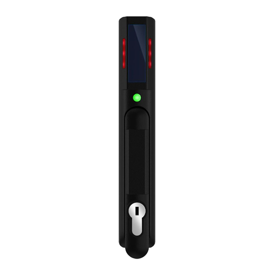
Page 87: Section 6 - Smartzone Security Handle
Section 6 – SmartZone Security Handle The Panduit Intelligent PDUs allow users to electronically secure and control access to cabinets. G5 PDU Firmware v3.1.19 (or higher is required). For the latest firmware please visit: panduit.com → Support → Download Center → PDUs Note: For security, verify that the handle is seated prior to engaging locking mechanism. -
Page 88: Figure 72: Connection Diagram For Smartzone Security Handle
Security Handle optimizing cable routing. Use the below table to help count total sensors being deployed. Part Number Number onboard Device connects to Sensors ACF05 Panduit G5 PDU ACF06 Panduit G5 PDU ACF11 Panduit G5 Handle ACF10 Panduit G5 Handle... -
Page 89: Configuring Cabinet Access Control
Panduit G5 PDU EC001 Panduit G5 PDU Note: A maximum of 8 sensors can be managed by the Panduit SmartZone G5 PDU controller. Configuring Cabinet Access Control All Rack Access Control configuration can be done under the Rack Access Control Page from the Web GUI. -
Page 90: Figure 73: Rack Access Control Web Gui
Figure 73: Rack Access Control Web GUI 3. The Actions Menu on the right side of the page will allow the user to Add Card, Rack Access Settings, Handle Settings, Keypad Settings, Remote Control, Beacon Settings, and Status LED Settings. Figure 74: Rack Access Control Actions Web GUI INTELLIGENT PDU USER MANUAL... -
Page 91: Adding A User For Local Rack Access
Adding a User for Local Rack Access Every user that needs access to the cabinet needs to have their access card added into the PDU. Each card (or user) must have a username and either a card ID or keypad PIN code. -
Page 92: Configuring Rack Access Settings
Figure 75: Local Rack Access Web GUI 2. Enter a username to identify the user. 3. If the system is configured for RFID Only or Dual Auth, enter the determined card Note: In the above example, the card ID is 258563 4. -
Page 93: Configuring Handle Settings
1. To update the rack access settings, select Rack Access Settings from the Actions menu. Figure 76: Rack Access Settings Web GUI 2. Select from two options in the Aisle Control. a. Hot/Cold Combined – Operating hot or cold causes both handles to open. -
Page 94: Configuring Keypad Settings
Figure 77: Handle Settings Web GUI 2. Select the handle to edit or get information about. a. Select the handle you are interested in, Under the PDU section. 3. Enter in the ACU Name. The ACU name is a name to help distinguish the different handles. -
Page 95: Remote Controlling The Handle
1. Card Only: Gain access to cabinet through swiping an authorized card 2. Keypad Only: Gain access to the cabinet through depressing an authorized secret pin into the keypad: a. PIN Mode turned on hides the user PIN in the web gui b. -
Page 96: Figure 78: Remote Control
Figure 78: Remote Control 2. Select the handle to control: a. Under the PDU section, Select the handle 3. Select the action you wish to perform. a. Lock remotely locks the handle b. Unlock remotely unlocks the handle. 4. When finished, click Close. INTELLIGENT PDU USER MANUAL... -
Page 97: Controlling The Beacon
Controlling the Beacon. The beacon is a visual indicator to give you status of the cabinet at a glance. The beacon will flash yellow when the cabinet is in a minor alarm or flash red when the cabinet has a critical alarm. You can also use the beacon’s locate function to flash the beacon a certain color to easily locate the cabinet. -
Page 98: Figure 80: Beacon Settings Web Gui
1. To control a handle beacon, select Beacon Settings Control from the Actions menu. Figure 80: Beacon Settings Web GUI 2. Select the function of the beacon: a. Standby –beacon color no alarms b. Locate –flash beacon 3. Select color for Standby or Locate. 4. -
Page 99: The Status Led
The Status LED The SmartZone Security Handle is equipped with a status LED to give a visual indication of the handle and security status. A summary of all the status LED states can be seen in the follow table. The default state of the status LED is on solid green. Status Status LED Table in Order of Priority: Status LED Color... -
Page 100: Setting Status Led State
Setting Status LED State 1. To set the standby state of the status LED state, select Status LED Settings from the Actions menu. Figure 81: Status LED Settings Web GUI 2. Select the color of Status LED when the handle is in standby state. 3. -
Page 101: Section 7 - Smartzone G5 Accessories
IT room atmosphere. Note: A maximum of 8 sensors can be managed by the Panduit SmartZone G5 PDU controller. Sensors may be installed with PDUs powered on. The following table lists available sensors as well as sensor count:... -
Page 102: Figure 82: Sensor Ports For Vertical Pdu
6m. A total of four extensions can be added to the leak detection sensor for a total length of 30m. SmartZone G5 Dry Input to the G5 iPDU and Contact Sensor (ACC01) designed to monitor a change in contact state. -
Page 103: Configuring Temperature Scale
Figure 83: Sensor Ports for Horizontal PDU Configuring Temperature Scale To configure the temperature scale (Celsius or Fahrenheit) of the temperature sensors: 1. Go to User Accounts. Figure 84: User Settings 2. The button at the top of the screen can be used to select Celsius or Fahrenheit. Figure 85:Celcius Setting Figure 86: Fahrenheit Setting Configuring Environmental Sensors... - Page 104 3. Open the Settings. 4. View the Threshold section on the Settings page. Select Threshold to configure sensors. 5. Go to External Sensors. 6. Select Edit button to configure the desired sensors. 7. In the Edit dialog box, type value of up critical, up warning, low warning, and low critical.
-
Page 105: Warranty And Regulatory Information
Warranty and Regulatory Information Warranty Information (http://www.Panduit.com) Regulatory Information Safety and regulatory compliance For important safety, environmental, and regulatory information, see Safety and Compliance Information at the Panduit website (http://www.Panduit.com) INTELLIGENT PDU USER MANUAL... -
Page 106: Panduit Support And Other Resources
Panduit Support and Other Resources Majority of your support needs can be met by visiting Panduit.com and navigating to the respective product page. If you require additional assistance; we are here to help. Accessing Panduit Support North America Europe / Middle East... -
Page 107: Acronyms And Abbreviations
Acronyms and Abbreviations LCD Liquid-Crystal Display LDAP Amps/Amperes Lightweight Directory Access Protocol Alternating Current OLED Organic Light-Emitting Diode Advanced Encryption Standard Power Distribution Unit Command Line Interface DHCP Quad-Network Interface Dynamic Host Configuration Protocol Redundant Network Interface Gigabyte Secure Hash Algorithms Graphical User Interface SNMP Simple Network Management Protocol... -
Page 108: Appendix A: Sensor Configuration
Figure 87: Door Switch Sensor Configuration Note: The Door Switch Sensor is only designed to connect to a Panduit PDU. Connecting it to another device may result in damage. -
Page 109: Temperature & Humidity Sensors
Figure 88: Dry Contact Cable Note: The dry contact cable is only designed to connect to a Panduit PDU. Connecting it to another device may result in damage. Temperature & Humidity Sensors Temperature and humidity sensors are designed to add comprehensive environmental monitoring to any Panduit PDU. -
Page 110: Configuring Environmental Sensors
Figure 89: Temperature and Humidity Sensors Configuring Environmental Sensors Each SmartZone G5 Intelligent PDU features an onboard controller capable of managing a maximum of 8 sensors. To configure the sensor location, alarms, notifications, and details, open the WEB Interface: 8. Open the Settings. -
Page 111: Figure 90: Temperature And Humidity Sensors
11. Select Edit button to configure the desired sensors. 12. In the Edit dialog box, type value of up critical, up warning, low warning, and low critical. 13. Select Save to exit the sensor setup. Repeat this process for additional sensors. Sensor Port Sensor Port Figure 90: Sensor Ports on controller... -
Page 112: Appendix B: Firmware Upgrade Options
Appendix B: Firmware Upgrade Options The firmware upgrade procedure verifies the image by validating the signature of the images. If the signature does not match, the firmware upgrade procedure will ignore the image and remain on the current version. Updating the firmware does not affect the configuration or outlet state of the intelligent PDU. -
Page 113: Usb Method
NOTE: the firmware file name must be retained AS IS. 1. Select Upload. The system will update the newest firmware to the Intelligent Network Controller. 2. When the upload is finished, the system will reboot automatically. USB Method Note: Verified to work with Toshiba or Sandisk up to 16GB USB Drives. - Page 114 3. Connect to the PDU via SSH using a program such as HyperTerm or PuTTY. 4. Login using a role with administration privileges. 5. Enter the command sys upd all. 6. It will show the message: System will enter upgrade mode after reboot, System Reboot now, Are you sure? (Y/N).
-
Page 115: Appendix C: Bulk Management Of Pdus
Appendix C: Bulk Management of PDUs A dedicated G5 Upgrade Tool (GUT) is included with every firmware release. This utility enables a user to bulk manage PDUs. This utility features Firmware Upgrading, Configuration Replication (common parameters) and management of uncommon parameters (.csv) file. -
Page 116: Figure 93: G5 Upgrade Tool Interface
Figure 93: System Management Screen WebGUI b. Insert IP Address or Range of the target PDU(s) c. Insert admin credentials d. Load the confi.ini file to the G5 Upgrade Utility and click Start Conf.ini Figure 94: G5 Upgrade Tool Interface 3. -
Page 117: Figure 94: System Management Screen Webgui
Figure 95: Example CSV File d. Load the Config.csv file to the G5 Upgrade Utility and click Start Config.csv Figure 96: G5 Upgrade Tool Interface SMARTZONE UPS USER MANUAL... -
Page 118: Appendix D: System Reset Or Password Recovery
Appendix D: System Reset or Password Recovery Use Reset Button on Controller Press and hold the Reset Button for 8 seconds to recover from an Intelligent Network Controller communication failure. This will cause a reset of the iNC controller, all configuration(s) will be retained. -
Page 119: Appendix E: Pdu Alarms
Appendix E: PDU Alarms PDU Unit Active Power Above upper critical PDU Unit Active Power Above upper warning PDU Unit PDU Unit Active Power Below lower warning PDU Unit Active Power Below Lower critical Input Phase X Voltage Above upper critical Input Phase X Voltage Above upper warning... - Page 120 Outlet X Immediate ON Outlet X Delayed ON Outlet X Immediate OFF Outlet X Delayed OFF Outlet X Immediate REBOOT Outlet X Delayed REBOOT Outlet X Cancel Pending Command External Sensor X (numerical) Above upper critical External Sensor X (numerical) Above upper warning External Sensor X (numerical) Below lower warning...
-
Page 121: Trap Codes Assigned To Alarms List
User Administration Password changed User Administration Password settings changed User Administration User Administration User added User Administration User deleted User Administration User modified Smart Rack Access Door Open Smart Rack Access Door Closed Smart Rack Access Smart Rack Access User Card Swiped Smart Rack Access Door Autolocked Trap Codes assigned to Alarms List Trap codes assigned for critical alarms:... - Page 122 value 100-147 The outlet (1-48) active power is BELOW critical threshold value 148-155 The sensor (1-8) temperature/humidity is ABOVE critical threshold value 156-163 The sensor (1-8) temperature/humidity is BELOW critical threshold value 164-171 The sensor (1-8) contact state is in alarm. 172-179 The sensor (1-8) lost communications.
- Page 123 203-205 The phase (1-3) voltage is ABOVE warning threshold value. 206-208 The phase (1-3) voltage is BELOW warning threshold value. 209-211 The phase (1-3) current is ABOVE warning threshold value. 212-214 The phase 1 current is BELOW warning threshold value. 215-226 The circuit breaker (1-12) current is ABOVE warning threshold value.
- Page 124 536-583 The outlet (1-48) DELAYED OFF occurred. 584-631 The outlet (1-48) IMMEDIATE REBOOT occurred. 632-679 The outlet (1-48) DELAYED REBOOT occurred. 680-727 The outlet (1-48) Cancel Pending Commands occurred. 728-735 The sensor (1-8) contact state is in cleared. Event log Cleared. Data log Cleared.
- Page 125 User xxx modified. Smart Rack Access Door Opened Smart Rack Access Door Closed Smart Rack Access User Card Swiped Smart Rack Access Door Autolocked Smart Rack Mechanical Lock Smart Rack Mechanical Unlock Trap codes assigned for information alarms: Trap Class Trap Trap Description Code Clear...
- Page 126 Trap codes assigned enhanced security alarms: Trap Class Trap Code Trap Description Warning 1100 Door Open for longer than configured door time out Critical 1101 Door Open for longer than configured max door open time Informational 1102 Door unlocked with authorized pin code 1103 Door accessed with unauthorized pin code.
-
Page 127: Appendix F: Panduit Network Controller Replace Or Rotate 180
Appendix F: Panduit Network Controller Replace or Rotate 180° 1. Use a T10 Torx screwdriver on the screws as shown in Figure 88. The screws are held in with retaining washers. Figure 97: Screws on Network Controller a. Controller may be rotated to accommodate overhead or underfloor power. If rotating controller, YOU MUST DISCONNECT the ribbon cable to prevent damage to the ribbon cable. -
Page 128: Figure 98: Screws On Network Controller
Ribbon Cable Figure 98: Ribbon Cable for the Network Controller 3. Replace and tighten the two (T10) screws on the Intelligent Network Controller to 2.2 – 3.1 lbf-in (0.25 – 0.35 N-M). Overtightening the screws may result in metal deformation. SMARTZONE UPS USER MANUAL... -
Page 129: Appendix G: Direct Connect To The Pdu By Changing Your Pc's Ip Address
Appendix G: Direct connect to the PDU by Changing Your PC’s IP Address Note: Instructions refer specifically to Windows 10. Please refer to your operating system documentation if you are not using Windows 10. 1. Type control into Windows Search and select Control Panel. Figure 99: Control Panel SMARTZONE UPS USER MANUAL... -
Page 130: Figure 100: Control Panel
2. In the Control Panel window, select View network status and tasks under the Network and Internet heading. Figure 100: Network Status and Tasks 3. Select Change adapter settings from the menu on the left. SMARTZONE UPS USER MANUAL... -
Page 131: Figure 101: Network Status And Tasks
Figure 101: Change Adapter Settings 4. Right-click Ethernet and select Properties. Figure 102: Properties SMARTZONE UPS USER MANUAL... -
Page 132: Figure 102: Change Adapter Settings
Figure 103: Ethernet Properties 5. Select Internet Protocol (TCP/IP) Version 4 (you may need to scroll down). Then click the Properties button. SMARTZONE UPS USER MANUAL... -
Page 133: Figure 104: Ethernet Properties
Figure 104: Internet Protocol Version 4 6. Select the Use the following IP address radio button. The Use the following DNS server addresses radio button then selects automatically. SMARTZONE UPS USER MANUAL... -
Page 134: Figure 105: Internet Protocol Version 4
Figure 105: IP Settings for Direct Connection Enter the following details into the appropriate boxes: • IP address: 192.168.0.10 • Subnet mask: 255.255.255.0 • Default gateway: 192.168.01 • Preferred SNS server: 192.168.0.1 7. Click OK to accept the entries. 8. Connect the PDU network connection directly to the PC’s Ethernet card using a patch cable. -
Page 135: Appendix H: Command Line Interface (Cli)
Appendix H: Command Line Interface (CLI) The Command Line Interface (CLI) is an alternate method used to manage and control the PDU status and parameters, as well as basic admin functions. Through the CLI a user can: • Reset the PDU •... - Page 136 Connecting to the CLI through the serial interface An option to communicating through the serial interface is to use the specialized YOST Serial Data Cable Panduit Part Number: MA017. This cable Remaps Panduit G5 Serial Interface to a YOST interface.
-
Page 137: Figure 107: Connect Ma017 To The Pdu In/Serial Port
• Data bits: 8 • Parity: None • Stop bits: 1 • Flow control: None Serial Cable Pinout to Create Your Own Cable Optionally if you prefer to make your own RJ45-to-DB9 Serial cable, the connections are wired as shown: Figure 107: Serial Cable Pinout Logging in with SSH via PuTTY 1. -
Page 138: Cli Commands
PDU user operation. PDU device setting. PDU power setting. System Commands Command Description Example sys date [year-month-day] Query or set system’s Panduit>sys date 2013-09- date. SUCCESS Panduit>sys date SUCCESS Date: 2013-09-19 Time: 03:49:46 sys time [hour:min:sec] Query or set system’s Panduit>sys time... - Page 139 System Reboot now, Are you sure? (Y/N):Y NOTE 1: There must be a valid file named Panduit.bin existing under directory/fw. NOTE 2: If in daisy chain configuration, master will also upgrade its all slave’s firmware.
-
Page 140: Network Commands
NOTE: There must be a valid file named conf.ini existing under directory/fw. sys log del event Delete event log file. Panduit>sys log del event, SUCCESS sys log edit data [on Configure data log PANDUIT>sys log edit data <interval> | off]... - Page 141 Command Description Example Panduit>net ssh on SUCCESS Panduit>net ssh off SUCCESS net ftps [on/off] Query or on/off FTPs. Net ftps SUCCESS FTPS Port: 21 Service is running Is Ftps net http [on/off] Query or on/off net http. Panduit>net http SUCCESS,...
-
Page 142: User Commands
SUCCESS Role ------------------------- admin admin user user User unlock<username> Unlock specified user. Panduit>usr unlock user SUCCESS Panduit>usr unlock admin SUCCESS NOTE: 1. Account would be locked temporarily if login failure excess “Maximum number of failed logins”. Use this command to unlock it. - Page 143 1; if in daisy chain, the master's PDUID is 1, others is ,2,3, dev outlet <PDUID> Query or set specified Panduit> dev outlet 1 1 off <outlet index> [on|off] PDUID and outlet-index's SUCCESS outlet status. SMARTZONE UPS USER MANUAL...
- Page 144 T1,TEMP 012345678 27.5 T3,TEMP 012345678 27.2 T2,TEMP 012345678 27.3 RH HUMI 012345678 44 dev ver <slipaddr> Query Panduit> dev ver 1 sensor/power/delay's Panduit> dev ver 15 firmware version. Panduit> dev ver 35 NOTE: relay: start from 1 power: start from 15...
- Page 145 : 0.0A active power: 0W apparent power: 0W power factor: 0.00 energy: 0.000kWh pwr phase <idx> Query specified phase’s Panduit> pwr phase 1 electric information. SUCCESS PDU PHASE 1 power Feature voltage: 0V current : 0.0A active power: 0W apparent power: 0W power factor: 0.00...
- Page 146 Command Description Example PDUs, this command is invalid. SMARTZONE UPS USER MANUAL...
-
Page 147: Appendix I: Radius Server Configuration
User-Role User VALUE User-Role Admin END-VENDOR Panduit 4. Load dictionary.Panduit by appending the following line to /etc/freeradius/3.0/dictionary $INCLUDE /usr/share/freeradius/dictionary.Panduit 5. Add authorized users to with the /etc/freeradius/3.0/mods-config/files/authorize desired role. (Note: the ‘users’ file location may vary based on unique customizations or different package managers.) When specified, the User-Role MUST be the first attribute of the user. - Page 148 User-Role. Note: You may need to change this example based on any client restrictions that are enforced. Usage: radtest [OPTS] user passwd radius-server[:port] nas-port-number secret # radtest 'radroleadmin' '34567890’ 192.0.2.1 0 'panduit#1' '' Sending Access-Request of id 212 to 192.0.2.1 port 1812 User-Name = "radroleadmin"...
-
Page 149: Appendix J: Panduit G5 Accessories
KE025X Option 5 Key for Tumbler TU025X Note: Panduit SmartZone G5 PDU Controller can handle a maximum of 8 sensors. Some part numbers have multiple sensors built in (e.g. EC001 has 4 sensors, ACF05 or ACF06 has 2 sensors). SMARTZONE UPS USER MANUAL... -
Page 150: Appendix K: Compliance Model Number Details
Appendix K: Compliance Model Number Details PP#&*%%-XXXX, where: XXXX: Series number. Shown different outlet combination %%: Input Current. 16 means 16A *: Form 0:0U 1:1U 2:2U &: Power Input: 1: 200-240Vac, 1 phase 2: 200-240/346-415 Vac (Wye), 3 phase 3: 100-120Vac, 1 phase 4: 200-240Vac (Delta), 3 phase 5: 100-240Vac, 1 phase 6: 120-208Vac (Wye), 3 phase... -
Page 151: Appendix L: Json Api Web Service
Appendix L: JSON API Web Service This API enforces constraints on certain JSON types: • Objects: may only be nested one level in a resource or 2 levels in a resource collection. • Numbers: must be within the range and precision defined by the property. •... - Page 152 POST Response /redfish/v1/AccountService/Accounts /redfish/v1/SessionService/Sessions DELETE /redfish/v1/AccountService/Accounts/{username} Response /redfish/v1/SessionService/Sessions/{session_id} For the code on any of the above listed interfaces – please refer to Panduit TR128-SZ G5 RestfulAPI.pdf For a copy of this document send a request to systemsupport@panduit.com SMARTZONE UPS USER MANUAL...
Need help?
Do you have a question about the Smartzone G5 and is the answer not in the manual?
Questions and answers