Advertisement
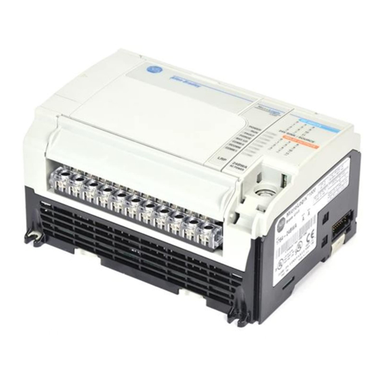
MicroLogix™ 1500 Programmable
Controller Base Units
(Catalog Numbers 1764-24AWA, 1764-24BWA, and
1764-28BXB)
http://literature.rockwellautomation.com/idc/groups/literature/documents/in/1
764-in001_-mu-p.pdf
Cette publication est disponible en français sous forme électronique (fichier PDF). Pour la
FR
télécharger, rendez-vous sur la page Internet indiquée ci-dessus.
Questa pubblicazione è disponibile in Italiano in formato PDF. Per scaricarla collegarsi al sito
IT
Web indicato sopra.
Diese Publikation ist als PDF auf Deutsch verfügbar. Gehen Sie auf die oben genannte
DE
Web-Adresse, um nach der Publikation zu suchen und sie herunterzuladen.
Esta publicación está disponible en español como PDF. Diríjase a la dirección web indicada
ES
arriba para buscar y descarga esta publicación.
Esta publicação está disponível em portugués como PDF. Vá ao endereço web que aparece
PT
acima para encontrar e fazer download da publicação.
Installation Instructions
Advertisement

Related Manuals for Rockwell Automation MicroLogix 1500


Summary of Contents for Rockwell Automation MicroLogix 1500
- Page 1 Installation Instructions MicroLogix™ 1500 Programmable Controller Base Units (Catalog Numbers 1764-24AWA, 1764-24BWA, and 1764-28BXB) http://literature.rockwellautomation.com/idc/groups/literature/documents/in/1 764-in001_-mu-p.pdf Cette publication est disponible en français sous forme électronique (fichier PDF). Pour la télécharger, rendez-vous sur la page Internet indiquée ci-dessus. Questa pubblicazione è disponibile in Italiano in formato PDF. Per scaricarla collegarsi al sito Web indicato sopra.
- Page 2 MicroLogix™ 1500 Programmable Controller Base Units Publication 1764-IN001B-EN-P - March 2008...
-
Page 3: Table Of Contents
Installation Instructions MicroLogix™ 1500 Programmable Controller Base Units (Catalog Numbers 1764-24AWA, 1764-24BWA, and 1764-28BXB) Inside... For More Information................4 Overview ....................5 Base Unit Description ................6 Hazardous Location Considerations ............7 Mounting the Controller ................. 9 Wiring the Controller ................13 Specifications .................. -
Page 4: For More Information
Table 1 Related Publications Refer to this Document Pub. No. A more detailed description of how to MicroLogix 1500 1764-UM001A-US-P install and use your MicroLogix 1500 Programmable Controllers User programmable controller. Manual A reference manual that contains data and MicroLogix 1200 and... -
Page 5: Overview
MicroLogix™ 1500 Programmable Controller Base Units Overview Install your controller using these installation instructions. Do not remove protective debris strips until after the base and ATTENTION all other equipment in the panel near the base is mounted and wiring is complete. Once wiring is complete, remove protective debris strips and install processor unit. -
Page 6: Base Unit Description
MicroLogix™ 1500 Programmable Controller Base Units Base Unit Description Table 2 Standard Base Units Catalog Number Base Unit I/O and Power Supply 1764-24AWA 120V ac inputs/ relay outputs/ 120/240V ac power supply 1764-24BWA 24V dc inputs/ relay outputs/ 120/240V ac power supply 1764-28BXB 24V dc inputs/ FET and relay outputs/ 24V dc power supply Table 3 Base Unit Description... -
Page 7: Hazardous Location Considerations
MicroLogix™ 1500 Programmable Controller Base Units Hazardous Location Considerations This equipment is suitable for use in Class I, Division 2, Groups A, B, C, D or non-hazardous locations only. The following WARNING statement applies to use in hazardous locations. EXPLOSION HAZARD WARNING •... - Page 8 MicroLogix™ 1500 Programmable Controller Base Units Environnements dangereux Cet équipement est conçu pour être utilisé dans des environnements de Classe 1, Division 2, Groupes A, B, C, D ou non dangereux. La mise en garde suivante s’applique à une utilisation dans des environnements dangereux. DANGER D’EXPLOSION MISE EN GARDE •...
-
Page 9: Mounting The Controller
(catalog numbers 1769-CRR1, -CRR3, -CLL1, -CLL3, -CRL1, -CRL3) must be used at the end of the group of I/O modules attached to the MicroLogix 1500 Controller. The end cap terminator is not provided with the base unit. A maximum of eight I/O modules may be connected to the base. - Page 10 MicroLogix™ 1500 Programmable Controller Base Units Mounting Dimensions Table 6 Dimensions Dimension 1764-24AWA 1764-24BWA 1764-28BXB Height (A) 138 mm (5.43 in.) Width (B) 168 mm (6.62 in.) Depth (C) 87 mm (3.43 in.) Controller Spacing The base unit is designed to be mounted horizontally, with the Compact™ expansion I/O extending to the right of the base unit.
- Page 11 MicroLogix™ 1500 Programmable Controller Base Units Using a DIN Rail The base unit and expansion I/O DIN rail latches lock in the open position so that an entire system can be easily attached to or removed from the DIN rail. The maximum extension of the latch is 15 mm (0.67 in.) in the open position.
- Page 12 MicroLogix™ 1500 Programmable Controller Base Units To remove your base unit from the DIN rail: 1. Place a flat-blade screwdriver in the DIN rail latch at the bottom of the base unit. 2. Holding the base unit, pry downward on the latch until the latch locks in the open position.
-
Page 13: Wiring The Controller
MicroLogix™ 1500 Programmable Controller Base Units To install your base unit using mounting screws: 1. Remove the mounting template from the inside back cover of this document. 2. Secure the template to the mounting surface. (Make sure your base unit is spaced properly, see “Controller Spacing”... - Page 14 MicroLogix™ 1500 Programmable Controller Base Units Wire Requirements Table 8 Wire Type Recommendation Wire Type Wire Size (2 wire maximum per terminal screw) Solid Cu-90°C (194°F) #14 to #22 AWG Stranded Cu-90°C (194°F) #14 to #22 AWG Wiring torque = 1.13 Nm (10 in-lb) rated; 1.3 Nm (12 in-lb) maximum Be careful when stripping wires.
- Page 15 The diameter of the terminal screw head is 5.5 mm (0.220 in.). The input and output terminals of the MicroLogix 1500 base unit are designed for the following spade lugs. The terminals will accept a 6.35mm (0.25 in.) wide spade (standard for #6 screw for up to 14 AWG) or a 4 mm (metric #4) fork terminal.
- Page 16 MicroLogix™ 1500 Programmable Controller Base Units Grounding the Controller ATTENTION All devices connected to the RS-232 channel must be referenced to base unit ground or floating. Failure to follow this procedure may result in property damage or personal injury. In solid-state control systems, grounding and wire routing helps limit the effects of noise due to electromagnetic interference (EMI).
-
Page 17: Specifications
MicroLogix™ 1500 Programmable Controller Base Units Specifications Table 9 General Specifications Description 1764-24BWA 1764-24AWA 1764-28BXB Number of I/O 12 inputs 12 inputs 16 inputs 12 outputs 12 outputs 12 outputs Line Power 85/265V ac 85/265V ac 20.4 to 30V dc Power Supply Inrush 120V ac = 25A 120V ac = 25A... - Page 18 MicroLogix™ 1500 Programmable Controller Base Units Table 10 Input Specifications Description 1764-24AWA 1764-24BWA and 1764-28BXB Inputs 0 thru 7 Inputs 8 and Higher On State Voltage 79 to 132V ac 14 to 30.0 V dc at 30°C 10 to 30.0 V dc at 30°C Range (86°F) (86°F)
- Page 19 MicroLogix™ 1500 Programmable Controller Base Units Table 13 1764-28BXB FET Output Specifications Specification General Operation High Speed Operation (Outputs 2 thru 7) (Outputs 2 and 3 Only) User Supply Voltage minimum 20.4V dc 20.4V dc maximum 26.4V dc 26.4V dc On-State Voltage at maximum load 1V dc...
- Page 20 MicroLogix™ 1500 Programmable Controller Base Units Table 14 Working Voltage Specification 1764-L24AWA Power Supply Input to Backplane Verified by one of the following dielectric tests: 1836V Isolation ac for 1 second or 2596V dc for 1 second 265V Working Voltage (IEC Class 2 reinforced insulation) Input Group to Backplane Isolation and Verified by one of the following dielectric tests: 151V...
- Page 21 MicroLogix™ 1500 Programmable Controller Base Units Table 14 Working Voltage Specification 1764-28BXB Input Group to Backplane Isolation and Verified by one of the following dielectric tests: 1200V Input Group to Input Group Isolation ac for 1 second or 1697V dc for 1 second 75V dc Working Voltage (IEC Class 2 reinforced insulation) FET Output Group to Backplane Isolation...
- Page 22 MicroLogix™ 1500 Programmable Controller Base Units Notes: Publication 1764-IN001B-EN-P...
- Page 23 MicroLogix™ 1500 Programmable Controller Base Units Notes: Publication 1764-IN001B-EN-P...
- Page 24 MicroLogix™ 1500 Programmable Controller Base Units Notes: Publication 1764-IN001B-EN-P...
- Page 25 MicroLogix™ 1500 Programmable Controller Base Units Notes: Publication 1764-IN001B-EN-P...
- Page 26 Mounting Template 168 mm 35 mm (6.62 in.) (1.37 in.) Expansion I/O Base Unit DIN rail center line. d'extension d'E/S Unité de base Ligne médiane du rail DIN. E/A- Grundeinheiten Mittellinie der DIN-Schiene. Erweiterungsmodule Unità di base Línea central del riel DIN. l’espansione dei Unidad Base moduli I/O...
- Page 27 New Product Satisfaction Return Rockwell Automation tests all of its products to ensure that they are fully operational when shipped from the manufacturing facility. However, if your product is not functioning and needs to be returned, follow these procedures.
Need help?
Do you have a question about the MicroLogix 1500 and is the answer not in the manual?
Questions and answers