Table of Contents
Advertisement
Quick Links
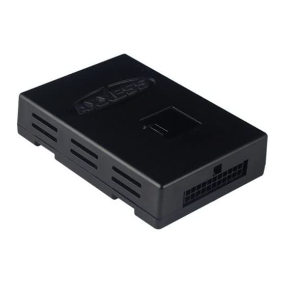
GM ONSTAR CLASS II DATA BUS INTERFACE
GMOS-05
Installation Instructions
The GMOS-05 is designed to be used in vehicles listed below to retain
Onstar and the warning chimes that are lost when the OEM radio is
removed, and also provide a 12 volt accessory output for proper after-
market radio operation. THE GMOS-05 NOW PROVIDES MUTE, PARK-
ING BRAKE, VSS OR SPEED SENSE, AND A REVERSE OUTPUT TO MAKE
INSTALLING AN AFTERMARKET NAVIGATIONAL RADIO SIMPLER AND
LESS TIME CONSUMING.
* READ IMPORTANT WARNING ON PAGE 1
BEFORE ATTEMPTING ANY INSTALLATION
*NOTE: This inteface will also work in vehicles listed
below that are NOT equipped with Onstar.
*NOTE: This inteface will NOT work to retain factory amplifiers.
INTERFACE COMPONENTS
• GMOS-05 Data Interface
• 14 pin harness with stripped leads
• 12 pin harness to 32 pin GM
1-800-221-0932
© COPYRIGHT 2004-2008 METRA ELECTRONICS CORPORATION
APPLICATIONS
BUICK
LeSabre 2000-05
OLDSMOBILE
Aurora 2001-03
PONTIAC
Bonneville 2000-05
harness with stripped leads
www.axxessinterface.com
Rev. 08-19-08
Advertisement
Table of Contents

Summary of Contents for Axxess GMOS-05
- Page 1 GMOS-05 Installation Instructions The GMOS-05 is designed to be used in vehicles listed below to retain Onstar and the warning chimes that are lost when the OEM radio is removed, and also provide a 12 volt accessory output for proper after- market radio operation.
- Page 2 GMOS-05 * READ IMPORTANT WARNING BEFORE ATTEMPTING ANY INSTALLATION * IMPORTANT WARNING THIS PRODUCT INCLUDES INSTRUCTIONS FOR INSTALLATION WHICH MUST BE CAREFULLY FOLLOWED. THE INSTRUCTIONS ARE WORDED IN SUCH A MANNER TO ASSUME THAT THE INSTALLER IS CAPABLE OF COMPLETING THESE TYPE OF ELECTRONIC INSTALLATIONS.
- Page 3 **Note: The ignition power source of most factory GM radios keep the radio on until one of the doors is opened. This is called the R.A.P. (retained accessory power). The GMOS-05 is designed to retain this feature.
- Page 4 2. Connect the Blue/Pink wire to the VSS or speed sense wire of the aftermarket navigation radio. 3. Connect the Green/Purple wire to the reverse wire of the aftermarket navigation radio. When completed, plug the 14 pin harness into the GMOS-05. CONNECTIONS TO BE MADE ON THE 32 PIN GM HARNESS: 1.
- Page 5 GMOS-05 5. Connect the the green/black wire to the amplifier’s left rear negative speaker output. 6. Connect the purple wire to the amplifier’s right rear positive speaker output. 7. Connect the purple/black wire to the amplifier’s right rear negative speaker output.
- Page 6 CHIME VOLUME ADJUSTMENT To adjust the chime volume,use a small screwdriver to rotate the potentiometer clockwise to make the chime louder and counterclockwise to make it softer. The potentiometer is located on the side of the GMOS-05. ONSTAR LEVEL ADJUSTMENT To adjust the Onstar volume level find the brown wire on the 12 pin harness.
- Page 7 GMOS-05...
- Page 8 GMOS-05 INSTRUCTIONS FINAL WIRING CONNECTIONS STRIP Make wiring connections using the EIA color code chart shown below and the SPLICE instructions included with the head unit. Metra recommends making connec- tions as shown below; Strip, Splice, Solder, Tape. Isolate and individually tape off ends of any unused wires to prevent electrical short circuit.


Need help?
Do you have a question about the GMOS-05 and is the answer not in the manual?
Questions and answers