Advertisement
Quick Links
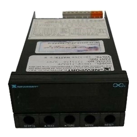
INFCP and INFCP-xxxB
Process Meter
For immediate technical or application assistance please call:
®
Newport Electronics, Inc.
2229 South Yale Street • Santa Ana, CA • 92704 • U.S.A.
TEL: (714) 540-4914 • FAX: (714) 546-3022
Toll Free: 1-800-639-7678 • http://www.newportUS.com • e-mail:info@newportUS.com
ISO 9001 Certified
Newport Technologies, Inc.
976 Bergar • Laval (Quebec) • H7L 5A1 • Canada
TEL: (514) 335-3183 • FAX: (514) 856-6886
Toll Free: 1-800-639-7678 • http://www.newport.ca • e-mail:sales@newport.ca
Newport Electronics, Ltd.
One Omega Drive • River Bend Technology Centre
Northbank, Irlam • Manchester M44 5BD • United Kingdom
Tel: +44 161 777 6611 • FAX: +44 161 777 6622
Toll Free: 0800 488 488 • http://www.newportuk.co.uk • e-mail:sales@newportuk.co.uk
Newport Electronics B.V.
Postbus 8034 • 1180 LA Amstelveen • The Netherlands
TEL: +31 20 3472121 • FAX: +31 20 6434643
Toll Free: 0800 0993344 • http://www.newport.nl • e-mail: sales@newport.nl
Newport Electronics spol s.r.o.
Rudé armády 1868, 733 01 Karviná 8 • Czech Republic
TEL: +420 69 6311899 • FAX: +420 69 6311114
Toll Free: 0800-1-66342 • http://www.newport.cz • e-mail: sales@newport.cz
Newport Electronics GmbH
Daimlerstrasse 26 • D-75392 Deckenpfronn • Germany
TEL: 49 7056 9398-0 • FAX: 49 7056 9398-29
Toll Free: 0800 / 6397678 • http://www.newport.de • e-mail: sales@newport.de
Newport Electronique S.A.R.L.
9, rue Denis Papin • 78190 Trappes • France
TEL: +33 130 621 400 • FAX: +33 130 699 120
Toll Free: 0800-4-06342 • http://www.newport.fr • e-mail: sales@newport.fr
Mexico and Latin America
TEL: 001-800-826-6342 • FAX: 001 (203) 359-7807
En Español: 001 (203) 359-7803
Using This Quick Start Manual
Use this Quick Start Manual to set up your Process Meter and begin
operation. Information is provided on how to:
• Connect ac power
• Set basic options for operation
• Connect the sensor
• Scale the meter.
Features with
are for the "B" version which has three-color
programmable "Big" LED display - All segment characters shown are
for the "B" version.
IMPORTANT: For complete information on all setup options,
please refer to the Operator's Manual.
NOTE: This Quick Start Manual includes specific configuration
parameters for transducers with an output range of 4–20 mA and
24 V excitation. Other sensor types may require different
parameters or additional ones. When this is the case, we refer you
to the Operator's Manual for detailed instructions.
Safety Consideration
This device is marked with the international Caution symbol.
The instrument is a panel mount device protected in accordance with
Class I of EN61010-1 (AC units) and Class III (DC units). Remember
that the unit has no power-on switch. Building installation should
include a switch or circuit-breaker that must be compliant to IEC 947-1
and 947-3.
SAFETY:
• Do not exceed voltage rating on the label located on the
top of the instrument housing.
• Always disconnect power before changing signal and
power connections.
• Do not use this instrument on a work bench without its
case for safety reasons.
• Do not operate this instrument in flammable or explosive
atmospheres.
• Do not expose this instrument to rain or moisture.
EMC:
• Whenever EMC is an issue, always use shielded cables.
• Never run signal and power wires in the same conduit.
• Use signal wire connections with twisted-pair cables.
• Install Ferrite Bead(s) on signal wire close to the instrument if
EMC problems persist.
Mount the Unit
1. Cut a panel opening using the
dimensions shown to the right.
2. Position the unit in the opening,
making sure the front bezel is
flush with the panel.
3. Install retaining clips on both
sides of the meter and tighten
against the panel.
Wiring
Warning: Do not connect AC power to your device until you
have completed all input and output connections. This
device must only be installed by a specially trained
electrician with corresponding qualifications. Failure to
follow all instructions and warnings may result in injury!
1. Remove the panel at the back of the unit.
2. Locate the TB1 connector.
3. Insert the correct wire in each terminal as shown in the following
figure and tighten the lockdown screws.
4. Tug gently on the wires to verify the connections.
2
External Fuse Required:
Time-delay, UL 248-14 listed
Time-lag, IEC 127-3 recognized
175 mA (115 Vac line)
125 mA (115 Vac line)
80 mA (230 Vac line)
63 mA (230 Vac line)
AC Powered Unit Connections
10-32 Vdc, 7.5 W
When using DC power, do not use internal excitation or
Isolated Analog Output for high color brightness. For
low or medium brightness, internal excitation is limited
to 24 V @ 25 mA, 5 V, 10 V, 12 V @ 35 mA.
In order to maintain the same degree of protection as the
AC units, always use a Safety Agency Approval DC source
with the same Overvoltage Category and Pollution Degree.
DC Powered Unit Connections
Connect the Sensor
1. Locate the TB2 connector on the rear of the unit.
2. Attach the sensor wires and tighten the lockdown screws.
The diagram below shows the wiring for 4–20 mA sensors
with internal excitation.
3. Tug gently on the wires to verify the connections.
4. Replace the panel at the back of the unit.
NOTE: Refer to the Operator's Manual for setup requirements
for other sensor types.
DEVICE
Current Input Connections (4–20 mA)
with Internal Excitation
3
Using the Configuration Menu
To configure the meter, you use the buttons on the front panel.
To:
Take This Action:
Display the
Press the MENU button. The first function
Configuration Menu on the menu, INPT, displays.
Select a submenu
1. Press MENU until the function you
function
want is shown.
2. Press
/TARE.
The information you can change flashes.
Select a value
1. Press
/MAX to display the option
for that submenu
you want.
function
2. Press MENU to store it.
STRD quickly flashes, indicating that
the selection has been stored in memory.
Then the next menu function displays.
Go back to previous Press RESET once.
menu function
Exit the
Press RESET twice. The unit displays
Configuration
RST as it reinitializes. When a numeric
Menu
value displays, the unit is in run mode.
(Optionally, you can press MENU to
move through all the menu functions
until the unit reinitializes.)
MENU
SUBMENU
/TARE
DESCRIPTION
100M,±50M, !10V, !±5V, 0-20 * Input
INPT
DEC.P
FFFF * , F.FFF, FF.FF, FFF.F
Decimal Point
RD.S.O
IN!1,
RD!1,
IN!2,
RD!2
Scale and Offset
RD.CF
R.1=T * , R.1=N
Reading Configuration
R.2=0, R.2=1, R.2=2, R.2=3, R.2=4 *
R.3=F * , R.3=U
COLR
GRN,
RED,
AMBR
Display Color
S1.CF
S.1=A * , S.1=B
Setpoint 1 Configuration
S.2=U * , S.2=L
S2.CF
S.1=A * , S.1=B
Setpoint 2 Configuration
S.2=U * , S.2=L
S1.DB
0003 *
Setpoint 1, Deadband
S2.DB
0003 *
Setpoint 2, Deadband
O.1=E * , 0.1=D
OT.CF
Analog Output
O.2=C * , 0.2=V
Configuration
O.3=A * , 0.3=P
O.4=D, 0.4=R
O.5=F, 0.5=H
P.BND
0000 shown if 0.3 = P
Proportional Band
M.RST
0000 shown if 0.3 = P
Manual Reset
OT.S.O
RD!1,
OUT1, RD!2,
OUT2
Output Scale & Offset
LK.CF
RS=E * , RS=D
Lockout Configuration
SP=E * , SP=D
L3=0 * , L3=1
BRIT
M.BrT, L.BrT, H.BrT
Display Brightness
* Factory Default Settings
4
To Set the Input Type
1. Press MENU until the unit displays:
2. Press
/TARE. The unit displays:
3. For this application you want 0-20. If 0-20 is not
displayed, press
/MAX until it appears. Other choices
are 100M, 50M, 10V and 5V.
NOTE: Refer to the Operator's Manual for more information
on changing ranges.
4. Press MENU to select the sensor shown. The meter
displays the next menu item. If you changed input type,
the meter displays:
To Set the Decimal Point
1. If it's not already shown, press MENU
until the unit displays:
2. Press
/TARE. The unit displays:
3. Press
/MAX to move the decimal
point to the desired location. The
choices are FFFF, F.FFF, FF.FF,
and FFF.F.
4. Press MENU to select the decimal point position shown.
The unit displays:
Advertisement

Related Manuals for Newport INFCP


Summary of Contents for Newport INFCP
- Page 1 TEL: 49 7056 9398-0 • FAX: 49 7056 9398-29 point to the desired location. The O.3=A * , 0.3=P NOTE: Refer to the Operator's Manual for setup requirements Toll Free: 0800 / 6397678 • http://www.newport.de • e-mail: sales@newport.de Wiring choices are FFFF, F.FFF, FF.FF, for other sensor types.
- Page 2 To define the maximum load ( IN!2 and RD!2 ): (AR) number immediately upon phone or written request. Upon examination by NEWPORT, if the unit is found to be defective it will be repaired or replaced information sent from another device such as a scale or a •...
Need help?
Do you have a question about the INFCP and is the answer not in the manual?
Questions and answers