Table of Contents
Advertisement
Advertisement
Table of Contents

Related Manuals for Newport 840-C


Summary of Contents for Newport 840-C
- Page 1 (217) 352-9330 | Click HERE Find the Newport 840-C at our website:...
- Page 2 Model 840-C HandHeld Optical Power Meter PERATOR ANUAL Artisan Technology Group - Quality Instrumentation ... Guaranteed | (888) 88-SOURCE | www.artisantg.com...
-
Page 3: Warranty
If found to be defective during the warranty period, the product will either be repaired or replaced at Newport’s option. To exercise this warranty, write or call your local Newport representative, or contact Newport headquarters in Irvine, California. You will be given prompt assistance and return instructions. -
Page 4: Ec Declaration Of Conformity
EC DECLARATION OF CONFORMITY Active Isolation Module Set Series Model 840-C We declare that the accompanying product, identified with the " " mark, meets the intent of the Electromagnetic Compatability Directive, 89/336/EEC and Low Voltage Directive 73/23/EEC. Compliance was demonstrated to the following specifications:... -
Page 5: Table Of Contents
Table of Contents Warranty ..............ii EC Declaration of Conformity ........iii iii. List of Figures ............. vi iv. List of Tables .............. vi Definitions ..............vii vi. Specifications ............viii Section 1 - General Information 1.1 Introduction ..............1 1.2 Manual Addenda ............ - Page 6 3.2 Preparation for Use ........... 14 3.2.1 Battery Charging ..........14 3.2.2 Sensor Connection/Removal ......15 3.2.3 Power Up ............16 3.3 Model 840-C Controller ..........17 3.3.1 Digital Display ..........17 3.3.2 Front Panel Controls ........18 3.3.3 Input Connectors ..........18 3.3.4 Analog Output ..........
- Page 7 5.1 Introduction ............... 31 5.2 Obtaining Service ............31 5.3 Service Form .............. 33 List of Figures Model 840-C Controller and Compatible Detectors ..............2 Simplified Functional Block Diagram ......7 Detector Cal Module Installation ......15 LCD Display Layout ..........16...
-
Page 8: Definitions
Definitions amps flameproof (when treated), rugged plastic Alternating Current Analog-to-Digital converter battery option biconic fiber connector standard coaxial connector type °C degrees Centigrade decibels decibels, referred to 1 mW power level direct current German National Standard EDCU Electronic Display and Control Unit PROM electrically eraseable, programmable read-only memory... -
Page 9: Specifications
Specifications Physical Specifications Electronic Display and Control Unit Dimensions: 7.2" x 3" x 1.5" Weight: 500 grams Enclosure: Flame resistant ABS Connectors: Input: 8-pin sub-mini DIN Analog Output: BNC Charger: DC power Jack, 5.5mm. Photodetectors See the appropriate instruction manuals and data sheets for these specifications Electrical Specifications... - Page 10 Analog Output Voltage: Current Accuracy Full Range Range +(%output + offset) Output 100nA 2.5% + 15mV 1µA 2% + 10mV C - 28 C, 1 year. Incl. I-V Converter and Output Amp.) Analog Output Response: 10µS time constant (typ.) A-D Output Accuracy: Absolute power measure- ment accuracy is typically limited by the calibration...
- Page 11 Temperature Coefficient: 0.1 x Appropriate Accuracy Specification/ Operating Environment: C to 50 C, <80% Relative Humidity up to 35 Reduce RH limit by 3%/ above 35 Storage Environment: C - 60 C, <90% Relative Humidity up to 35 Reduce RH limit by 3%/ above 35 Power: 6V, 600mA NiCd battery...
-
Page 12: Section 1 - General Information
This instruction manual contains the necessary informa- Introduction tion for operation and maintenance of the Newport Model 840-C HandHeld Power Meter as well as information for troubleshooting and obtaining service if necessary. This information is divided into the following sections: •... -
Page 13: Product Description
*Memory Modules sold with Detectors as shown in dashed boxes. Figure 1 Model 840-C Controller and Compatible Detectors The Model 840-C operates with Newport’s line of optical detectors through the use of an in-line calibration module. This Cal Module supplies calibration and detec- tor information while still allowing the detector to be detached and used with other equipment in the lab. -
Page 14: General Warnings And Cautions
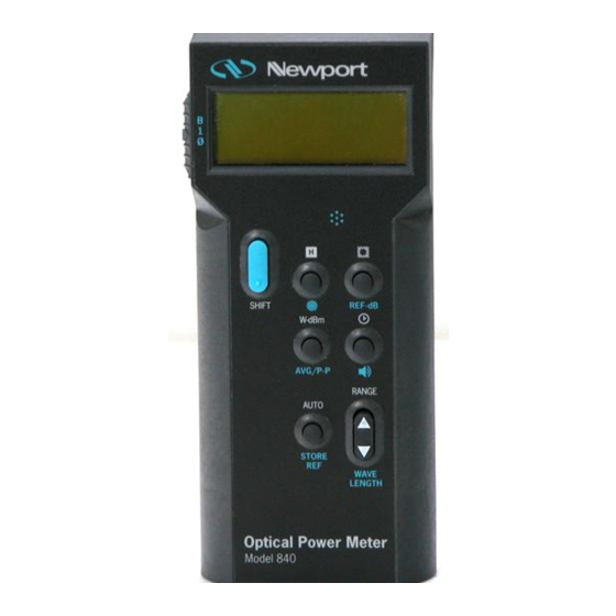
The Model 840-C has been designed with the most frequently used keys placed within natural reach. A backlit 4-digit liquid crystal display (LCD) permits easy reading in darkened areas. An audio indicator allows the user to maximize a signal without having to look at the display. -
Page 15: Getting Started
Please carefully read this instruction manual before using Getting Started the Model 840-C HandHeld Power Meter. Alignment of the detector may require care and patience for optimum performance in some situations. Be especially careful to observe the warnings and cautions throughout this manual (see Section 1.8). -
Page 16: Safety Symbols And Terms
Saftey Symbols The following safety terms are used in this manual: and Terms The WARNING heading in this manual explains dangers that could result in personal injury or death. The CAUTION heading in this manual explains hazards that could damage the instrument. In addition, a NOTES heading gives information to the user that may be beneficial in the use of this instrument. -
Page 17: Section 2 - Principles Of Operation
Memory calibration information about its matched photodetector Module to the 840-C power meter. It is connected to the photode- tector via a BNC connector and to the electronic display by a sub-miniature eight-pin DIN connector. The memory module is separate from the power meter so that photosensor and memory modules can be quickly changed without opening up the electronic display. -
Page 18: Functional Description
DC current ranges, four AC current ranges, and a photodetector. A simplified block diagram of the Model 840-C is shown in Figure 2. The input amplifier, a low noise current-to-voltage (I-V) converter, buffers and amplifies the incoming signal. This stage is... -
Page 19: Dc Range Electrical Accuracy And Overload Conditions
Table 1 DC Range Electrical Accuracy and Overload Conditions Power Maximum Current Accuracy ± Range Reading Range (%Rdg + %Full Scale) ° ° C - 28 100.0 nW 99.99 nW 100.0 nA 0.5 + 0.05 1.000 µW 1.000 µA 999.9 nW 0.25 + 0.05 10.00 µW 10.00 µA... -
Page 20: Input Amplifier
Model 840-C is turned off. 2.4.3 AC Wall Mount Adaptor The Model 840-C may be operated off line power through the use of the supplied AC Adaptor. This unit accepts AC line power (mains power) and provides a DC voltage to –... -
Page 21: Ni-Cd Rechargeable Batteries
2.4.5 Reset Switch There is a Reset push button switch available for the 840-C. It would, when pressed, momentarily, reset the 840-C. It is accessible via an opening on the backside of the 840-C. Use a non-conductive tool to access it. -
Page 22: Quantum Detector Temperature Effects
2.5.3 Ambient and Stray Light Ambient and stray light striking the detector will be measured by the Model 840-C, and should be considered when making careful measurements. Ambient light can be distinguished from dark current by either turning off or blocking the source and covering the detector face with opaque material, such as a piece of black metal. -
Page 23: Environmental Measurement Conditions
The effects of ambient light are greatly reduced when using a fiber-connectorized input with the Model 840-C. If free space beam measurements are desired, using the supplied attenuator will reduce stray light, and often improve the ratio of source signal to that due to the ambient conditions. -
Page 24: System Accuracy
Artisan Technology Group - Quality Instrumentation ... Guaranteed | (888) 88-SOURCE | www.artisantg.com... -
Page 25: Section 3 - System Operation
This section contains the information needed to prepare and operate the Model 840-C as a power meter. Operation consists of using the Model 840-C to perform basic DC and AC peak-to-peak optical power measurements, compen- sating for dark current and ambient light, making ratio and logarithmic (dBm, dB) measurements, using the audio output and other functions. -
Page 26: Sensor Connection/Removal
Align the line on the memory module with the mark on the head of the Model 840-C power meter (See Fig. 3). Slide the module into the tube until the 8-pin sub-mini DIN connector begins to engage. Some small rotational adjustment of the module may be necessary when engaging the connector. -
Page 27: Power Up
(LCD) are momentarily turned on (approx. 3 sec.) for visual confirmation by the user (See Figure 4). If the display is blank, then turn 840-C off. Press the reset switch located in the back of the 840-C, using a non- conductive tool. Turn the 840-C on. nµmW... -
Page 28: Model 840-C Controller
If the Model 840-C is being powered up for the first time after new batteries are installed or if the battery has deep discharged, it will automatically enter a default mode of operation. -
Page 29: Front Panel Controls
3.3.2 Front Panel Controls OFF/ON/BKLT — Three position slide switch found on side of Model 840-C near the display. The switch posi- tions represent meter off ( 0 ), meter on with no backlit display ( 1), and meter on with backlit display ( B ). -
Page 30: Analog Output
The analog output permits monitoring or recording of the signal from the current-to-voltage converter within the Model 840-C. Since the analog output scales from 0 to 1V for each gain stage of the input transimpedance amplifier, as the meter autoranges, the output voltage will develop discrete voltage jumps. -
Page 31: Definition Of Key Functions
Key Functions displayed value of sensor current measured by the front end amplifier to account for calibration values or display units. A valid key input is responded by the 840-C with a short audio response. 3.4.1 , Shift The , SHIFT key toggles the keyboard between white and blue functions. -
Page 32: Avg/P-P
When in the AVG mode the DC power is displayed. The front end of the Model 840-C ranges to obtain the best possible A/D resolution of this signal when in AUTO mode. The DC signal displayed is the result of an A/D conversion using an integration time of 100ms. -
Page 33: Tone
, Tone , TONE key toggles the audio output of the Model 840-C on or off. When on, the Model 840-C indicates signal level through the frequency of an audio beeper. The higher the signal level, the higher the frequency. When in... -
Page 34: Wavelength
See the appropriate detector manual for this information. Further discussion on these topics for Newport detectors is found in Section 2.5 of this manual. 3.5.1 Setting the Wavelength In order to obtain accurate optical power measurements,... -
Page 35: Setting The Attenuator Status
Model 840-C can be used. The calibration constants stored in the Detector Cal Module span only the wavelength range appropriate for the detector and are specific to that detector. -
Page 36: Power Measurements
NOTE The transmission characteristics of each attenuator are slightly different; the user must, therefore be careful to use ONLY the attenuator and detector pair with the same serial numbers for which the particu- lar Detector Cal Module is calibrated. 3.5.3 Power Measurements Select autoranging for automatic power level shifting, or select manual ranging to the desired range for the expected power level. -
Page 37: Logarithmic Measurements (Dbm And Db)
3.5.6 Logarithmic (Log) Measurements (dBm and dB) The Model 840-C can make logarithm (dBm and dB) measurements referenced to either a 1 mW power level or to any other observed power level with the use of the REF-dB key. The basic procedure for using the Log mode is to select autorange and press the W-dBm key (dBm annunciator turns on). -
Page 38: Log Measurements: Other Reference Powers (Db)
The stored power reading is then algebraically divided into all subsequent power level readings and displayed (in dB). The Model 840-C is now set up to make decibel (dB) measurements referenced to the stored power level. Simply input the power to be measured and take the reading from the display. -
Page 39: Store And Recall Of Reference Power
3.5.6.3 Store and Recall of the Long Term RAM Reference Power The Model 840-C can store and recall from long term RAM memory the reference power level it uses to make decibel (dB) measurements. To view this power level, perform the following steps: Perform step a. -
Page 40: Section 4 - Maintenance And Troubleshooting
CAUTION Do not use acetone or other organic solvents on the Model 840-C. Organic solvents attack the ABS Case. Troubleshooting The following troubleshooting guide is intended to isolate Guide... - Page 41 Table 4 Symptom/Fault Troubleshooting Guide (continued) Symptom Possible Fault/Correction Readout with dBm or L0 - Current underflow. Decrease RANGE on meter or increase signal. Readout is 0F - Sensor signal saturation. Decrease signal to the sensor. Unit does not respond - Hold function is on.
-
Page 42: Section 5 - Factory Service
Calibration data for an individual detector is stored in the Detector Cal Module that accompanies each detector. The Model 840-C may be used with other Newport detector/ attenuator combinations than the one supplied with the unit so long as an Detector Cal Module is calibrated for that detector. - Page 43 Artisan Technology Group - Quality Instrumentation ... Guaranteed | (888) 88-SOURCE | www.artisantg.com...
-
Page 44: Service Form
Service Form Newport Corporation U.S.A. Office: 949/863-3144 FAX: 949/253-1800 Name ____________________________________ Return Authorization # _______________ Company _________________________________ (Please obtain prior to return of item) Address __________________________________ Country __________________________________ Date _________________________________ P.O. Number ______________________________ Phone Number _______________________ Item(s) Being Returned: Model # __________________________________ Serial # ______________________________... - Page 45 Artisan Technology Group - Quality Instrumentation ... Guaranteed | (888) 88-SOURCE | www.artisantg.com...
- Page 46 Notes Artisan Technology Group - Quality Instrumentation ... Guaranteed | (888) 88-SOURCE | www.artisantg.com...
- Page 47 1791 Deere Avenue Irvine, CA 92606 (In U.S.): 800-222-6440 Tel: 949-863-3144 Fax: 949-253-1680 Internet: sales@newport.com Visit Newport Online at: www.newport.com P/N 17492-02, Rev. J Newport Corporation, Irvine, California, has IN-03901 (08-00) been certified compliant with ISO 9001 by Printed in the USA the British Standards Institution.
Need help?
Do you have a question about the 840-C and is the answer not in the manual?
Questions and answers