Table of Contents
Advertisement
Advertisement
Table of Contents

Related Manuals for Newport 1917-R


Summary of Contents for Newport 1917-R
- Page 1 Model 1917-R Hand-held Laser Power Meter User’s Manual...
-
Page 2: Warranty
INDIRECT, SPECIAL, OR CONSEQUENTIAL DAMAGES RESULTING FROM THE PURCHASE OR USE OF ITS PRODUCTS. First printing 2011 © 2011 by Newport Corporation, Irvine, CA. All rights reserved. No part of this manual may be reproduced or copied without the prior written approval of Newport Corporation. -
Page 3: Declaration Of Conformity
Electromagnetic Compatibility Directives: 89/336/EEC The EMC Directive, 73/23/EEC Low Voltage Directive Model Number: 1917-R Power Meter Year mark affixed: 2011 Type of Equipment: Electrical equipment for measurement, control and laboratory use. -
Page 4: Technical Support Contacts
Return the product to Newport Corporation, freight prepaid, clearly marked with the RMA# and we will either repair or replace it at our discretion. Newport is not responsible for damage occurring in transit and is not obligated to accept products returned without an RMA#. -
Page 5: Safety Information
Safety Information Do not use the 1917-R if the device or the detector looks damaged, or if you suspect that the 1917-R is not operating properly. Appropriate installation must be done for water-cooled and fan-cooled detectors. Refer to the specific instructions for more information. The user must wait for a while before handling these detectors after power is applied. -
Page 6: Table Of Contents
Table of Contents Warranty Declaration of Conformity Technical Support Contacts Safety Information List of Illustrations 1 General Information Introduction ...................7 Unpacking..................7 Parts List..................7 Specifications ................7 Front Panel Description..............9 Connector Description..............12 2 System Operation Making a Power Measurement............13 Display Description ..............15 3 Batteries Battery Selection .................17 Battery Installation ..............17... -
Page 7: List Of Illustrations
Fig. 1-1 1917-R Front Panel ................9 Fig. 1-2 1917-R Top Panel ................12 Fig. 1-3 1917-R LCD Display ..............15 Fig. 1-4 1917-R Needle display in tail mode..........15 Fig. 1-5 1917-R Needle display in Bar Graph mode ........16... -
Page 8: General Information
1.3 Parts List The following is a list of parts included with the 1917-R Hand-held Power Meter. Please make sure everything is present before discarding packing materials. - Page 9 60mA (with external 9 VDC power supply) CAUTION Permanent damage to the optical meter may occur if an external power supply other than the Newport PM-PS9 (200960A) is used. Please call Newport Corporation if extra power supplies are needed for a particular setup.
-
Page 10: Front Panel Description
1.5 Front Panel Description Backlight / I/O Control Key Switches the 1917-R on and off (press for at least 2 seconds to turn off the 1917- R) and toggles backlight on and off when the 1917-R is on (backlighting is available only when the 1917-R is powered by the external 9 VDC power supply). - Page 11 Refer to p.13, adjusting the zero (steps 6 to 8). The 1917-R will redo the zero every time you press the zero button for two seconds, reboot the 1917-R if you wish to remove the zero cancellation.
- Page 12 Range down can be manually selected using the range down button.. Digital high Control Keys Displays the maximum recorded values. To return to measurement display mode, press the key again. Digital low / W/dBm Control Keys Displays the maximum recorded values. To return to measurement display mode, press the key again.
-
Page 13: Connector Description
1.6 Connector Description Fig. 1-2 1917-R Top Panel PROBE INPUT JACK: The 1917-R uses a DB-15 female connector to mate with the detectors. See section 2.1 for compatible detector list. 0 to 1 VOLT ANALOG OUTPUT: For monitoring laser average power by using external equipment such as a chart recorder, a computer with an analog interface, a voltmeter, etc. -
Page 14: System Operation
1- Install the power detector on its optical stand. 2- With the 1917-R turned off , connect the power detector head to the 1917-R using the PROBE INPUT JACK (see Fig. 1-2). It is recommended to turn the 1917-R off before connecting a new detector head in order to prevent any loss of information from the detector head’s EEPROM. - Page 15 8- To reset the zero, wait until the reading has stabilized and press the Zero button on the front panel for at least 2 seconds. The 1917-R will display “Zero“ for a moment and then return to the normal measurement mode. You are now ready to make an accurate measurement.
-
Page 16: Display Description
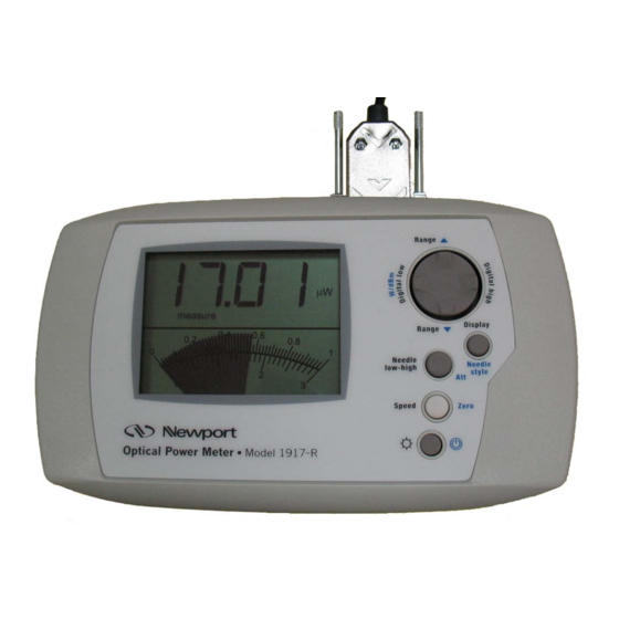
The 1917-R LCD display provides measurement information, wavelength information, attenuator selection and other useful messages. The upper part of the screen displays 1917-R setting information and digital values from the measurements. The numeric display minimum resolution is 0.1% of the full scale. The smallest value that can be displayed is 0.01 pW. -
Page 17: Fig. 1-5 1917-R Needle Display In Bar Graph Mode
1917-R on again. If the detector is not recognized by the 1917-R, the message “Bad Detector” will be displayed. Make sure you use a detector head that is compatible with the 1917-R (see section 1.2 for the list of compatible detector heads). -
Page 18: Batteries
1917-R and recharged with an external charger. The batteries need to be replaced if the 1917-R displays “LO BATT” on its digital display or if it does not power-up when the I/O control key is pressed 3.2 Battery Installation... -
Page 19: Battery Removal
Lift the kickstand. Open and remove the battery door. Hold down the 1917-R and slowly but firmly pull on the nylon strap to remove the batteries. Do not use a pointed tool to remove the batteries as it may puncture them. -
Page 20: Service Information
3. Firmware version 4. Description of the problem. If the instrument is to be returned to Newport Corporation, you will be given a Return Authorization Number (RMA), which you should reference in your shipping documents. Please fill out a copy of the service form, located on the following page, and have the information ready when contacting Newport Corporation. -
Page 21: Service Form
Service Form Newport Corporation U.S.A. Office: 800-222-6440 FAX: 949/253-1479 Name _______________________________ Return Authorization #__________________ (Please obtain RMA# prior to return of item) Company ________________________________________________________________________ Address ________________________________ ____________________Date _________________ Country _______________________ Phone Number ______________________________________ P.O. Number ___________________ FAX Number _______________________________________ Item(s) Being Returned:... -
Page 22: Recycling And Separation Procedure
Recycling and Separation Procedure This section is used by the recycling center when the power meter reaches its end of life. Breaking the calibration seal or opening the power meter enclosure will void the 1917-R warranty. The complete 1917-R power meter contains:... - Page 23 (In U.S.): 800-222-6440 Tel: 949-863-3144 Fax: 949-253-1680 Internet: sales@newport.com Visit Newport Online at: www.newport.com Newport Corporation, Irvine, California; Evry and Beaune-La-Rolande, France have all been certified compliant with ISO 9001 by the British Standards Institution. Mountain View, California is DNV certified.
Need help?
Do you have a question about the 1917-R and is the answer not in the manual?
Questions and answers