
Related Manuals for Newport QuantX-300


Summary of Contents for Newport QuantX-300
- Page 1 User’s Guide Quantum Efficiency Measurement Solution QuantX-300 700514 February 2019...
-
Page 3: Table Of Contents
Safety Considerations ....................7 Initial Inspection ......................8 Product Overview ..................... 12 Features of the QUANTX-300 .................. 13 Specifications ......................14 Options and Accessories ..................15 Chapter 2: Assembly and Start-Up Instruction .......... 17 ... - Page 4 Monitor Detector Calibration ..................60 Reflectance Detector Calibration ................65 Measurement of Sample PV Cell ................69 Appendix A: QUANTX-300 System Wavelength Check ......77 Appendix B: QUANTX-300 Monochromator Resolution ......85 February 2019 QUANTX-300...
-
Page 5: Safety And Warranty Information
Mains supply voltage fluctuations are not to exceed ±10% of the nominal supply voltage. Maximum Relative Humidity: <85% RH, non-condensing Operating temperature range of 18 °C to 28 °C Storage and transportation temperature of –40 °C to 70 °C This equipment is suitable for continuous operation. February 2019 QUANTX-300... -
Page 6: Safety Marking Symbols
Oriel Instruments shall not be liable for any incidental, special, or consequential damages. If a problem occurs, please contact Oriel Instruments with the instrument's serial number, and thoroughly describe the nature of the problem. February 2019 QUANTX-300... -
Page 7: Returning An Instrument
Oriel Instruments Customer Support. You may contact us in whatever way is most convenient: Phone (406) 586-1244 (406) 586-9405 OrielPV.Sales@newport.com Mail to: Oriel Instruments 31950 East Frontage Road Bozeman, Montana, U.S.A 59715-8642 www.newport.com/oriel February 2019 QUANTX-300... - Page 8 Oriel Instruments; Oriel recommends you insure the shipment. If the original shipping container is not available, place your instrument in a container with at least 3 inches (7.5 cm) of compressible packaging material on all sides. We look forward to serving you even better in the future! February 2019 QUANTX-300...
-
Page 9: Chapter 1: Introduction And Specifications
Options and accessories Specifications Safety Considerations If any of the following symptoms exist, or are even suspected, remove the QUANTX-300 from service. Do not use the QUANTX-300 until trained service personnel can verify safe operation. Visible damage ... -
Page 10: Initial Inspection
Initial Inspection When the QUANTX-300 is received, verify that the following items were received with the instrument. The QUANTX-300 ships as four separate packages. 1. QUANTX-300 Instrument Package a. Primary QUANTX-300 instrument body (PN: 603618) QUANTX-300 Instrument 2. Sample Stage Package a. - Page 11 M6-1.0 x 25 mm Screws x4 (PN: C1JR06025G) Hex Ball Drivers, 3/16, 9/64, 1/8, 3/32, 1/16 (PN: 90-11-044, 90-11-047, 90-11- 046, 90-11-044, 90-11-042) Mounting Hardware and Tools c. Standards Hi-Low Reflectance Standard (PN: 603414) February 2019 QUANTX-300...
- Page 12 BNC to SMA, 36 inch x2 (PN: 403391) BNC to SMA, 24 inch x1 (PN: 403387) for 603621 detector BNC to Clip Lead, 18 inch (PN: 403246) BNC to Binding Post Adapter (PN: 403223) QUANTX-300 Cable Kit February 2019 QUANTX-300...
- Page 13 Laptop Power Cable (included with 800244) h. USB Thumb Drive – Software, Documents, and Data Manual Certifications Calibration Standards Data QUANTX Software Installers QUANTX-300 Control Computer, and USB Drive loaded with Software, Documentation, and Data February 2019 QUANTX-300...
-
Page 14: Product Overview
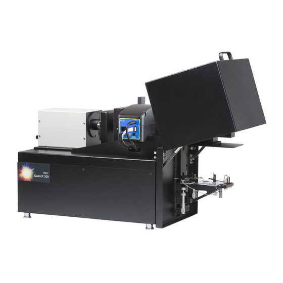
The product is a turn-key solution which includes all necessary components with integrated light source, monochromator, detectors, electronics, software, and even the computer. The QUANTX-300 incorporates a patented detector geometry using a beam splitter, allowing for simultaneous measurement of EQE and the reflective losses to quantify IQE and a patent pending circuit that protects your cell when being connected and disconnected from building up charges that can potentially damage your PV cell. -
Page 15: Features Of The Quantx-300
Integrated +/-10 V Voltage bias Includes calibrated reflectance standards Multiple user selectable gain stages to support a broad range of input signal levels The QUANTX-300 Quantum Efficiency Measurement System February 2019 QUANTX-300... -
Page 16: Specifications
Slit to bandwidth conversion for monochromator as configured with 600 lines/mm gratings is 13.3nm/1mm slit width. Excludes Diffuse measurement for standard product. As specified by Newport for CS130B over narrow wavelength range. May be larger uncertainty near low and high ends of wavelength range. -
Page 17: Options And Accessories
Options and Accessories Options and accessories available for the QUANTX-300 Quantum Efficiency Measurement Solution: DESCRIPTION MODEL / PART NUMBER Temperature Controlled Vacuum Chuck IQE-200B-TC-VAC Electrical Contact Probe Kit - Magnetic PVIV-PROBE-KIT Light Biasing Kit – Delivers white or filtered sample biasing... - Page 18 February 2019 QUANTX-300...
-
Page 19: Chapter 2: Assembly And Start-Up Instruction
Procedure: Place the QUANTX-300 onto the optical bench surface in an easily-accessible location Locate two holes nearest any two supporting feet on the base of the QUANTX-300 Repeat for both mounting brackets: Place the semi-circular end of the mounting bracket around the supporting foot. - Page 20 1 – Sample Stage (PN: 603354) Procedure: Locate slide rail on QUANTX-300 on the right side of the instrument Sample Stage Slide Rail Unscrew thumb screw on left side of sample stage until only a few threads are holding the screw into the stage (or until the end of the screw is flush with the bottom of the V-groove on the inside of the stage mount.
- Page 21 Right Side of Sample Stage Aligned Pivot the sample stage to align the left side of the sample stage to the left side of the slide rail. Using the left hand, tighten the thumb screw to secure the stage. February 2019 QUANTX-300...
- Page 22 Before beginning this step, ensure that the main power supply is disconnected. When working with any lamp, handle carefully, and do not touch the bulb with bare fingers. PROCEDURE Locate the lamp housing on the QUANTX-300. February 2019 QUANTX-300...
- Page 23 Lamp Housing Location of Lamp Housing on the QUANTX-300 Using the Phillips screwdriver, remove the screws from the left and right sides of the top cover of the lamp housing (4). Remove the lamp housing cover. Remove the lamp cage connector retention cover by removing the thumbscrew and set aside.
- Page 24 Guide the reflector rim into the recessed lamp seat, using the two white pegs as rests for guiding the lamp into place. o Make sure the Anode wire is centered within the cutout at the top of the lamp seating plate. Lamp Seating February 2019 QUANTX-300...
- Page 25 Replace the lamp cage connector retention cover and secure the thumbscrew. Replace the top cover, sliding it straight down. Replace the four (4) Phillips head screws in the top cover, tightening securely. Properly Mounted Lamp February 2019 QUANTX-300...
- Page 26 Chapter 4). Monochromator Connections Ensure the monochromator cables are connected o Both the power and USB cables protruding from the QUANTX-300 body should be connected to the correspondingly labeled connectors on the side of the monochromator. February 2019 QUANTX-300...
- Page 27 Ensure the lamp power cable is connected. Lamp Power Switch and Connector Rear Panel Connections Before beginning this step, inspect power cables to ensure the correct terminals exist for the region in which the QUANTX-300 is being installed. February 2019 QUANTX-300...
- Page 28 BNC connector on the rear panel, labeled MONITOR (B) in the figure above. o The monitor and reflectance cables may be secured to the QUANTX-300 chassis using the included 1/8” Allen wrench through the existing cable loops. February 2019...
- Page 29 220-240V~ o Connect the corresponding end of the Power Cable to the power connector (E) on the rear panel of the QUANTX-300. o Connect the other end of the power cable into a live outlet.
-
Page 30: Quantx-300 Start-Up
PROCEDURE Switch the main QUANTX-300 system power switch on the rear panel to the “on” position. Listen for the chopper wheel to begin rotating. To avoid heating of the chopper wheel, it must be spinning before turning on the lamp. -
Page 31: Quantx-300 Shut-Down
The QUANTX software will launch and initiate operation. QUANTX Software Icon QUANTX-300 Shut-Down This procedure describes the correct, safe way to shut down the QUANTX-300. STEP 1: STOP THE QUANTX SOFTWARE The software must be closed before powering off the system. Powering off or disconnecting the USB cable from the system while the software is running will result in an error state within the software. - Page 32 As noted above, do not proceed to this step until the lamp cooling fans have stopped. PROCEDURE Switch the mains power switch on the back of the QUANTX-300 main chassis to the “off” (O) position. The USB and AC power cables may now be removed from the system.
-
Page 33: Chapter 3: Description Of Components
Chapter 3: Description of Components This chapter is a general description of the components that make up the QUANTX-300 Quantum Efficiency Measurement Solution. Back Panel Connections QUANTX-300 Back Panel Connections The back panel of the instrument is laid out to make connection to the stage, sample, and system detectors easy and straight forward. - Page 34 120V and 220-240 VAC. Refer to the rear panel for the correct rating of fuse for each range. On / Off Switch – The instrument main power switch is on the back of the unit. The lamp can be February 2019 QUANTX-300...
-
Page 35: Tip-Tilt Stage
Main switch. Tip-Tilt Stage The QUANTX-300 comes with a Tip-Tilt stage to aid the user in correctly placing and connecting to the sample. The installation of the stage is described in the assembly Instructions. -
Page 36: Reflectance Standard
A second connection is made through the probe contacting a bus bar next to the beam position. Reflectance Standard The IQE200B ships with a calibrated reflectance standard designed to provide reliable and repeatable measurements when used with the IQE200B. February 2019 QUANTX-300... - Page 37 603414 QUANTX-300 Specular Reflectance Standard The housing contains both a high and low reflectance standard. The calibration files for the standard are included on the computer that ships with the system. The machined recess in the top of the holder lies at the same height as the surface of the reflectors to give you a scattering surface to see the beam and adjust the sample stage height until the focal plane is reached.
- Page 38 The high and low reflectance standard surfaces are the same height as the target etched on the holder. The test sample also matches the height of the focal plane so little to no vertical stage adjustment is necessary between calibration and testing. February 2019 QUANTX-300...
-
Page 39: Calibrated Reference Detector
The housing contains a standard SMA port to connect a cable to the back panel BNC input of the system labeled “Sample”. The platform on the side of the reference detector, on which is printed a white rectangle, is the height where the QUANTX-300 beam should be focused to perform to its calibrated responsivity. - Page 40 Note that this cell is not intended for use to verify system performance specifications. Newport recommends using calibrated reference cell model 91150V for this purpose. This reference cell is accredited to the ISO/IEC 17025 standard by our PV Calibration and Test Lab. Please contact a Newport sales engineer for more information.
-
Page 41: Chapter 4: Quantx Software
Chapter 4: QUANTX Software The QUANTX-300 system includes a software application to operate the system. The software is icon based to make the operation straightforward for a wide audience of users. The computer that ships with the system comes with the software pre-installed. To launch the software double click on the desktop icon. - Page 42 PV samples. Spectral Response of the PV sample, measured in Amps per Watt (A/W) over the wavelength range of the scan External Quantum Efficiency of the PV sample measured in x100% over the wavelength range of the scan. February 2019 QUANTX-300...
- Page 43 Sends to current, visible Print Visible graph on main screen to Graph local printer. Enables floating pop up window with short circuit current density Jsc values Jsc Calculator calculated from current scan at various conditions including AM0, AM1.5, AM1.5D+C. February 2019 QUANTX-300...
- Page 44 When multiple plots are displayed, the scan titles are shown here and they may Plot Legend be toggled on or off by the checkboxes. The first plot line is reserved for current data February 2019 QUANTX-300...
-
Page 45: Chopper Control
4Hz to 100Hz measuring PV cells with slow response times. Use arrows to increase/decrease chopper Increment/ ±0.1Hz and settable to 0.1Hz speed or enter desired value. Press enter decrement to set chopper frequency to new value. Default 25Hz February 2019 QUANTX-300... - Page 46 February 2019 QUANTX-300...
-
Page 47: Filter Wheel Control
± 10nm if a feature of interest in your scan lies near one of default switch-over wavelengths. Filter Settings Window Filter Settings Window The switch-over wavelength can be adjusted using a) slider, b) increment/decrement arrows or c) entering desired number. Hit enter key to for selection to take effect. February 2019 QUANTX-300... - Page 48 The filter wheel will rotate immediately after you make your selection as indicated by an audible motor sound. The QuantX-300 is fitted with a standard 5-position filter wheel of which only 3 positions are being used with the additional two positions reserved for wavelength expansion.
-
Page 49: Monochromator Control
600 lines/mm ruled diffraction gratings, one blazed at 370nm for the visible range and the other at 1000nm for the near infrared range. The input/exit slit on the QUANTX-300 has been factory set at 750µm for a 10nm FWHM bandwidth and protected from accidentally bumping the micrometers by protective covers. - Page 50 This is normal. Sets the center wavelength of the Set to visible wavelength such as 555nm Function monochromator manually to aid in beam alignment on to the sample. 325 – 1800nm Range February 2019 QUANTX-300...
- Page 51 Press “SET” button to save scan values Monochromator Grating Control The CS130B monochromator contains two, 600 lines/mm ruled diffraction gratings blazed at 350nm for the visible range and 1000nm for the near infrared range. The grating switch over control allows February 2019 QUANTX-300...
- Page 52 1100nm so no switch over the diffraction gratings is needed. . Range 325– 1800nm Typical = 1110nm Use arrows to increase/decrease Increment/ wavelength. Press enter to set wavelength decrement to new value. Default 1110nm February 2019 QUANTX-300...
-
Page 53: Monitor Calibration Controls
Once calibrated, measured signals from the PV samples and reflectance detectors are divided by the monitor detector signal to make the measurements independent of lamp intensity fluctuations. The monitor calibration is needed to calculate spectral response (SR) and external quantum efficiency (EQE) of the sample. February 2019 QUANTX-300... - Page 54 Bias Voltage – Read out of the bias voltage on the calibrated reference detector. This should be zero (or very near 0) as indicated by the green text for an accurate calibration. If the bias voltage is not zero (red), visit the sample screen and zero the bias voltage before calibration. February 2019 QUANTX-300...
-
Page 55: Reflectance Measurement Controls
The sample reflectivity is needed to calculate the IQE from the EQE of the sample. The reflectance detector signal is divided by the monitor detector signal to make the measurements independent of lamp intensity fluctuations. February 2019 QUANTX-300... - Page 56 To advance to the second reflectance calibration screen, a reflectance file should automatically load (2), select New (5) or Load Previous (6), and Save (11) the results. The second calibration will replace the first screen. February 2019 QUANTX-300...
-
Page 57: Diffuse Measurement Controls
Calibration must be saved to complete the calibration Home – Exits calibration screen and returns to home screen. Diffuse Measurement Controls This is a place holder for future support of diffuse measurements. February 2019 QUANTX-300... -
Page 58: Sample Measurement Controls
PV samples. It includes voltage bias control for your sample, sample connection to the system, gain, and an enable/disable switch to safely connect the electrical output of your sample to the detection circuit. The details of these features are outlined in the chart below February 2019 QUANTX-300... - Page 59 Advanced gain settings yield access to independent selection of DC and AC gain, as well as the signal coupling. February 2019 QUANTX-300...
- Page 60 Active (Volts) – graph of the chopped optical signal as function of time. Sample must be enabled for the chopped signal to be accurate. Home – Exits sample screen and returns to home IQE screen. You can leave the sample screen with the sample either Enabled or Disabled. February 2019 QUANTX-300...
-
Page 61: Chapter 5: Calibration And Measurement
These procedures assume the QUANTX-300 is set up and running and the QUANTX-300 software application has just been launched and is in control of the system. Please configure the system and follow the calibration steps listed below to familiarize yourself with the calibration process. -
Page 62: Monitor Detector Calibration
4. Move the detector so that the beam is transmitted into the circular port on the top of the detector housing. 5. The beam should be centered in the port. A card may be used to aid in centering the beam, as shown below: February 2019 QUANTX-300... - Page 63 If you can’t see the output, verify wavelength is set to a visible value such as 555nm. Center beam on to detector surface. Enable Sample (calibrated reference detector) and verify chopped signal is being plotted on the Active graph at the bottom of the Sample Screen. February 2019 QUANTX-300...
- Page 64 Active signal should have square tops/bottoms with amplitude of 1-2 Vpp. Note if the chopped signal has wavy or non-flat tops/bottoms you may need to shield the detector from room lights by placing the supplied 1.5” tube on top of the detector. February 2019 QUANTX-300...
- Page 65 “Scan” tab in the graph area. Monitor = Blue Curve Reference Detector = Green Curve NOTE: If signals exceed 10V at Xe emission peaks, reduce gain on appropriate detector and repeat scan. Click on “Save” when scan is complete February 2019 QUANTX-300...
- Page 66 The chart below suggests the conditions you can use the “Load Previous Calibration” feature to save time recalibrating the system if it is unchanged from the last time it was calibrated. If there is ever a question, please perform a new calibration. February 2019 QUANTX-300...
-
Page 67: Reflectance Detector Calibration
Make sure the high and low reflection surfaces are clean and free of dust. 2. Center the High R reflector under the output beam of the QUANTX-300 Center the high reflective sample under the output beam at 555nm. - Page 68 Check the calibration curve for the High R standard is what you expect under the “Reflectivity” tab in the graph area at the bottom of the screen Verify wavelength is tuned to a visible value such as 555nm Adjust gain settings to: Mode: Basic Gain: 1M February 2019 QUANTX-300...
- Page 69 “Reflectivity” tab in the graph area at the bottom of the screen Note: No gain values are offered on this screen because the high and low reflective standards must be calibrated at the same gain values February 2019 QUANTX-300...
- Page 70 See table above for suggestions when to use this feature. Click on “Home” to return to main screen. Verify Reflectance detector is calibrated as indicated by a green border surround the detector value on the main screen. February 2019 QUANTX-300...
-
Page 71: Measurement Of Sample Pv Cell
The BNC end connects to the “sample” port of the back panel of the QUANTX-300. NOTE: the sample could also be connected to the 4-wire terminal port and configured for two-wire operation. See Chapter 3 for details. - Page 72 SR and EQE response will be too low and the reflectivity Rs will be too high. If beam overlaps the bus bars on the sample cell (left) the measurements of the cell will be inaccurate. Move the sample cell over until the beam lies between the bus bars (right). February 2019 QUANTX-300...
- Page 73 Active graph at the bottom of the Sample Screen. Adjust gain settings to: Mode: Basic Gain: 100K NOTE: Changing the gain values on the sample will not void the system calibration. This allows you to February 2019 QUANTX-300...
- Page 74 Increase specular reflection greater than the overall reflection of the PV sample. Adjust the tip/tilt on the sample stage to optimize the amplitude of the active reflected signal if necessary. Click on “Home” to return to main screen. February 2019 QUANTX-300...
- Page 75 IQE = Internal Quantum Efficiency (x100 %) Rs = Specular Reflectance (x100 %) Mon = Raw Monitor Signal (Volts, lockin value) Ref = Raw Reflectance Signal (Volts, lockin value) Sam = Raw Sample Signal (Volts, lockin value) February 2019 QUANTX-300...
- Page 76 AM0 = E-490 with no atmosphere AM0 = Wehril with no atmosphere AM0 = ASTM with no atmosphere AM1.5G = 48.2 from zenith, 1.5atmospheres AM1.5D+C = Direct + Circumsolar 1.5 atmospheres February 2019 QUANTX-300...
- Page 77 20mV error which is noticeable at this low bias voltage. Disable the sample in preparation for a new scan with bias voltage applied. This is done automatically at the beginning of a new scan in case you forget February 2019 QUANTX-300...
- Page 78 10. To see an earlier measurement, “load” the previous log file to see what the IQE values were for zero voltage bias. There is no way to overlap the two plots in the same graph at this time – please look for this feature in the next revision of the QUANTX-300 application. February 2019...
-
Page 79: Appendix A: Quantx-300 System Wavelength Check
PROCEDURE 1. Power on the QUANTX-300 according to the Start-Up procedure in Chapter 2. The lamp should be allowed to warm up for about 30 minutes to stabilize. 2. Remove the monochromator slit adjustment covers. - Page 80 3. Adjust the slit width to 75 µm. This is 7.5 on the micrometer scale. February 2019 QUANTX-300...
- Page 81 6. Click the start scan button to run the scan. 7. When the scan is complete, check for the two tallest peaks in this scan range. They are strong Xenon emission lines and should be located at 823nm and 882nm as shown below. February 2019 QUANTX-300...
- Page 82 750µm (75 on the micrometer scale, or 1.5 full clock-wise revolutions from zero). 9. If the peaks are not within this tolerance, then they must be corrected using the procedure below. February 2019 QUANTX-300...
- Page 83 1. In the scan below, the two peaks are off of their ideal value by +1 nm. This indicates that the monochromator calibration is slightly off. The peaks should be at 823nm and 882nm, but they are actually at 824nm and 883nm. 2. Close the QuantX application and open the Monochromator Utility application on the desktop. February 2019 QUANTX-300...
- Page 84 4. We will use the peak found at 824nm to correct the wavelength calibration of the monochromator. 5. Input “824” into the “Set Wavelength” field of the monochromator utility and press <Enter> to send the monochromator to that wavelength. February 2019 QUANTX-300...
- Page 85 7. Since the peak found at 824nm should actually be at 823nm, input this into the “Calibrate Wavelength” field of the Calibration Settings popup window and press <Enter>. Press “OK” in the warning message box that appears. February 2019 QUANTX-300...
- Page 86 9. If the monochromator cannot be recalibrated such that the Xenon emission lines appear in the correct location, or if the wavelength is off by a large amount on initial receipt of the instrument (>10nm), please contact Oriel support for assistance. February 2019 QUANTX-300...
-
Page 87: Appendix B: Quantx-300 Monochromator Resolution
Maximum bandwidth recommended by ASTM E1021-06 It is recommended to match the FWHM bandwidth with the wavelength step size for best resolution and maximum output power of the QUANTX-300. Recommended settings are listed in the following chart: Slit width Notes FWHM <... - Page 88 Unscrew the micrometer on the entrance slit CCW until it passes 0mm on the scale indicating the slit is fully closed. You can watch the output of the QUANTX-300 vanish (if set to a visible wavelength like 555nm) as the slit closes. It will not harm the slit to turn the micrometer beyond zero.
Need help?
Do you have a question about the QuantX-300 and is the answer not in the manual?
Questions and answers