Vaisala GMP252 User Manual
Carbocap carbon dioxide probe
Hide thumbs
Also See for GMP252:
- User manual (132 pages) ,
- Quick manual (14 pages) ,
- Quick start manual (2 pages)
Table of Contents
Advertisement
Quick Links
Advertisement
Table of Contents

Related Manuals for Vaisala GMP252


Summary of Contents for Vaisala GMP252
- Page 1 M211897EN-B User Guide Vaisala CARBOCAP Carbon Dioxide Probe GMP252...
- Page 2 This product contains software developed The contents of this manual are subject to by Vaisala or third parties. Use of the change without prior notice. software is governed by license terms and Local rules and regulations may vary and...
-
Page 3: Table Of Contents
4.4.1. Installing the Driver for the USB Service Cable......... 23 4.5. Accessing Serial Commands from Modbus or Analog Mode......23 4.6. Enabling Modbus Mode from Vaisala Industrial Protocol.......24 4.7. Changing From Digital Output to Analog Output........... 25 4.8. Serial Commands....................25 4.9. - Page 4 8.3. Analog Output Error State..................74 Technical Data.....................75 9.1. GMP252 Specifications..................75 9.2. Spare Parts and Accessories................78 9.3. GMP252 Probe Dimensions................78 9.4. 243261SP Mounting Flange Dimensions............79 9.5. 243261SP Calibration Adapter Dimensions............80 Appendix A: Modbus Reference................81 A.1. Function Codes..................... 81 A.2.
- Page 5 List of Figures Figure 1 GMP252 Probe Parts................... 9 Figure 2 Probe Cuvette with Mirror and Sensor Chips..........11 Figure 3 CO2 Measurement in the Measurement Cuvette........12 Figure 4 Example of Analog Output Overrange Behavior ........15 Figure 5 GMP252 Dimensions..................17 Figure 6 Probe with 243261SP Installation Flange.............18...
- Page 6 GMP252 User Guide M211897EN-B List of Tables Table Document Versions....................7 Table 2 Related Documents....................8 Table 3 Applicable Patents....................8 Table 4 Analog Output Overrange Clipping and Error Limits........14 Table 5 M12 Male Connector...................20 Table 6 Default Serial Interface Settings..............21 Table 7 Basic Serial Commands..................26...
- Page 7 Table 51 Modbus Measurement Data Registers (Read-Only)........81 Table 52 Modbus Configuration Data Registers (Writable)........82 Table 53 Modbus Status Registers (Read-Only)............84 Table 54 Device Identification Objects................84...
- Page 8 GMP252 User Guide M211897EN-B...
-
Page 9: About This Document
Chapter 1 – About This Document 1. About This Document 1.1. Documentation Conventions DANGER! alerts you to a fatal hazard. If you do not read and follow instructions carefully at this point, death will follow. WARNING! alerts you to a serious hazard. If you do not read and follow instructions carefully at this point, there is a risk of injury or even death. -
Page 10: Related Manuals
Quick Guide 1.4. Trademarks Vaisala and CARBOCAP are registered trademarks of Vaisala Oyj. Windows is either a registered trademark or trademark of Microsoft Corporation in the United States and other countries. All other product or company names that may be mentioned in this publication are trade names, trademarks, or registered trademarks of their respective owners. -
Page 11: Product Overview
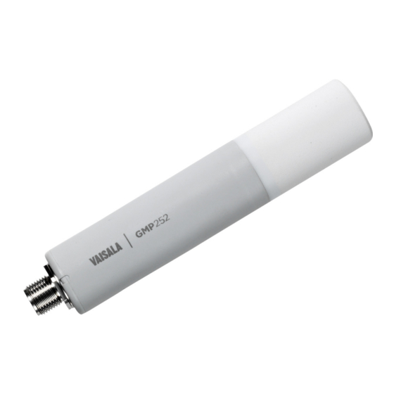
The probe is based on Vaisala’s patented 2nd generation CARBOCAP technology and equipped with Vaisala's Microglow infrared light source. The probe is easy to install with a plug-in/plug-out M12 connection. GMP252 is able to compensate for temperature, pressure and background gas. For temperature compensation purposes, the probe includes an internal temperature sensor that allows measurement compensation according to ambient temperature. -
Page 12: Basic Features And Options
• Voltage output (0 ... 5 V or 0...10 V) • Compatible with MI70 hand-held meter. • Easy plug-in, plug-out. More Information ‣ GMP252 Specifications (page 75) ‣ Operating Principle of CO2 Measurement (page 11) ‣ Environmental Compensation (page 12) ‣ Modbus (page 57) -
Page 13: Operating Principle Of Co Measurement
Chapter 2 – Product Overview 2.3. Operating Principle of CO Measurement The Vaisala CARBOCAP sensor used in the probe is a silicon-based, nondispersive infrared (NDIR) sensor for the measurement of gaseous carbon dioxide in air-like gases. Figure 2 Probe Cuvette with Mirror and Sensor... -
Page 14: Environmental Compensation
GMP252 User Guide M211897EN-B Figure 3 CO Measurement in the Measurement Cuvette Gold-plated mirror Light absorbed by CO in the measured Hermetic window Fabry-Perot interferometer Light source (Microglow) Hermetic window Thermopile detector 2.4. Environmental Compensation When necessary, various environmental compensations can be applied to improve the CO measurement accuracy of the probe. -
Page 15: Temperature Compensation
2.4.2. Pressure Compensation The probe does not have on-board pressure measurement. However, a pressure reading from an external source can be used as a setpoint value for compensation using Vaisala Industrial Protocol or Modbus. If pressure compensation is turned off, the probe uses the default compensation value of 1013 hPa. -
Page 16: Probe Startup
GMP252 User Guide M211897EN-B 2.5. Probe Startup When powered on, the probe starts up within 12 seconds. Measurements from the outputs (digital and analog) become available during this time but note that they will only reach specified accuracy after a 2-minute warm-up period. For this reason, you should design your system so that it does not rely on measurements from the probe during this time. -
Page 17: Analog Output Overrange Example
Chapter 2 – Product Overview More Information ‣ Analog Output Error State (page 74) 2.6.1. Analog Output Overrange Example Consider a probe with 0 ... 5 V output, scaled to 0 ... 2000 ppmCO • When the measured CO rises above 2000 ppmCO , the output rises above 5 V. -
Page 18: Safety
2.7.1. ESD Protection Electrostatic Discharge (ESD) can cause immediate or latent damage to electronic circuits. Vaisala products are adequately protected against ESD for their intended use. However, it is possible to damage the product by delivering electrostatic discharges when touching an exposed contact on the product. -
Page 19: Installation
3.3. Installation Accessories The probe can be installed through a surface using the optional flange accessory (Vaisala product code 243261SP, or attached for example to a wall with the optional clip accessory (two-clip set, Vaisala product code 243257SP. -
Page 20: 243261Sp Installation Flange
GMP252 User Guide M211897EN-B 3.3.1. 243261SP Installation Flange The optional flange accessory is used to install the probe body through a wall or other surface. Figure 6 Probe with 243261SP Installation Flange 4 Phillips head screws (included) Installation flange (diameter 60 mm) with four Ø 4.2 mm screw holes... -
Page 21: 243257Sp Mounting Clips
Chapter 3 – Installation 3.3.2. 243257SP Mounting Clips The optional mounting clips (set of two clips) are used to hold the probe in place for example on a wall or other surface. Each clip base attaches to the installation surface with one screw (screw hole Ø... -
Page 22: Wiring
GMP252 User Guide M211897EN-B 3.5. Wiring Table 5 M12 Male Connector Pin# Function Note Cable 223263SP Wire Colors Power in • With digital output: 12 ... 30 VDC Brown • With voltage output: 12 ... 30 VDC • With current output: 20 ... 30 VDC Typical average power consumption <0.4 W, maximum... -
Page 23: Vaisala Industrial Protocol
4. Vaisala Industrial Protocol 4.1. Overview RS-485 line of the probe provides an implementation of the Vaisala Industrial Protocol that can be used for service and configuration use, or for interfacing with the system to which the probe is integrated. The protocol is a plaintext protocol suitable for use both by human operators and automated systems. -
Page 24: Connecting With A Computer
Windows and a USB computer connection cable. Connecting with a computer allows you to configure and troubleshoot your probe using serial line commands. 1. If you have not used the Vaisala USB cable before, install the driver before attempting to use the cable. -
Page 25: Installing The Driver For The Usb Service Cable
5. The installation has reserved a COM port for the cable. Verify the port number, and the status of the cable, using the Vaisala USB Instrument Finder program that has been installed in the Windows Start menu. Windows will recognize each individual service cable as a different device, and reserve a new COM port. -
Page 26: Enabling Modbus Mode From Vaisala Industrial Protocol
‣ Enabling Modbus Mode from Vaisala Industrial Protocol (page 24) 4.6. Enabling Modbus Mode from Vaisala Industrial Protocol If you need to switch from Vaisala Industrial Protocol to Modbus mode, you must configure the following settings: • Serial line operating mode •... -
Page 27: Changing From Digital Output To Analog Output
Chapter 4 – Vaisala Industrial Protocol 3. Set the Modbus address to 240 with the addr command: addr 240 4. Set the serial line settings to 19200/N/8/2 with the seri command: seri 19200 N 8 2 5. Power off (disconnect) the probe or reset with the reset command. The new configuration is available at the next restart. -
Page 28: Table 7 Basic Serial Commands
GMP252 User Guide M211897EN-B Table 7 Basic Serial Commands Command Description Device information and status Show probe information. Show probe information (will respond in POLL mode). errs Show currently active errors. help Show list of currently available serial commands. snum Show probe serial number. -
Page 29: Table 8 Advanced Serial Commands
Chapter 4 – Vaisala Industrial Protocol Command Description reset Reset the probe. pass [1300] Access advanced serial commands. Table 8 Advanced Serial Commands Command Description Serial line output and communication addr [0 … 254] Show or set probe address. Analog output amode Show or set analog output mode (analog output limits and error level). -
Page 30: Device Information And Status
Show listing of device information even if device is in poll mode and connection has not been opened using the open command. Example: Device : GMP25x Copyright : Copyright (c) Vaisala Oyj 2016. All rights reserved. SW Name : GMP25x SW version : 1.0.0 SNUM : GMP233_5_18... -
Page 31: Table 11 Help Command
Chapter 4 – Vaisala Industrial Protocol Table 11 Help Command Syntax Description help<cr> Show list of currently available serial commands. Example (showing a list of the basic commands): help ADATE ADDR ATEXT CLOSE ERRS FORM HELP INTV PASS ESET SDELAY SEND... -
Page 32: Table 13 System Command
GMP252 User Guide M211897EN-B Table 13 System Command Syntax Description system<cr> Show probe firmware information. Example: system Device Name : GMP25x SW Name : GMP25x SW version : 1.0.0 Operating system : TSFOS1.0 Table 14 Time Command Syntax Description time<cr> Show how long the probe has been in operation since the last startup or reset. -
Page 33: Serial Line Output And Communication
Chapter 4 – Vaisala Industrial Protocol 4.10. Serial Line Output and Communication Table 16 Addr Command Syntax Description addr<cr> Show current device address. Addresses are required for POLL mode. addr [aaa]<cr> Set new device address. aaa = address, 0 ... 254 (default = 0) - Page 34 GMP252 User Guide M211897EN-B Syntax Description form [sss]<cr> Set a new measurement format. sss = String consisting of modifiers and abbreviations for measured parameters. See Table 19 on the facing page and Table 20 on the facing page. Maximum length is 150 characters. Maximum length may be shorter when text strings are used.
-
Page 35: Table 19 Output Parameters For Form Command
Chapter 4 – Vaisala Industrial Protocol Syntax Description Example (set output format as CO ppm with Modulus-65536 checksum): form 6.0 "CO2=" CO2 " " U3 " " CS4 #r #n Output example (continuous output from RUN mode): CO2= 3563 ppm 9F... -
Page 36: Table 20 Modifiers For Form Command
GMP252 User Guide M211897EN-B Output Parameter Abbreviation in Form Command o2comp Currently used oxygen concentration compensation value rhcomp Currently used relative humidity compensation value Table 20 Modifiers for Form Command Modifier Description Length modifier (number of digits and decimal places). Tabulator. -
Page 37: Table 21 Intv Command
Chapter 4 – Vaisala Industrial Protocol Table 21 Intv Command Syntax Description intv<cr> Show the output interval of the automatically repeating measurement messages (r command and run mode). intv [iii uuu]<cr> Set the output interval. iii = interval, range 0 ... 255. -
Page 38: Table 23 R Command
GMP252 User Guide M211897EN-B Table 23 R Command Syntax Description r<cr> Start the continuous outputting of measurement values as an ASCII text string to the serial line. The probe keeps outputting measurement messages at the interval that has been set with the intv command until stopped with the s command. -
Page 39: Table 26 Send Command
Chapter 4 – Vaisala Industrial Protocol Syntax Description Example (set delay to 50 milliseconds): sdelay 50 COM transmit delay : 50 Table 26 Send Command Syntax Description send<cr> Output a single measurement message. send [aaa]<cr> Output a single measurement message from a device in poll mode. -
Page 40: Table 28 Smode Command
GMP252 User Guide M211897EN-B Syntax Description seri [b p d s]<cr> Set new serial line settings. The new settings will be taken into use when the probe is reset or powered b = baud rate (9600, 19200, or 38400) p = parity •... -
Page 41: Analog Output
Chapter 4 – Vaisala Industrial Protocol Syntax Description smode [mode]<cr> Set serial line start-up operating mode. New mode is taken into use when the device is reset or powered Available modes: stop = No automatic output. All commands available. Default mode. -
Page 42: Table 30 Aover Command
GMP252 User Guide M211897EN-B Syntax Description amode [channel lo_value hi_value Set new analog output limits and error output value. error_value]<cr> channel = Analog output channel • 1 = voltage output (V) • 2 = current output (mA) lo_value = Low limit of the channel. - Page 43 Chapter 4 – Vaisala Industrial Protocol Syntax Description aover [channel clipping error_ Set the behavior of the analog output when the limit]<cr> measured value is outside the scaled output range. channel = Analog output channel • 1 = voltage output (V) •...
- Page 44 GMP252 User Guide M211897EN-B Syntax Description Example (for channel 1): 1. View currently set analog output scaling (asel command), limits and error level (amode command), and overrange behavior (aover command): pass 1300 asel 1 Aout 1 quantity : CO2(0 ... 2000) amode 1 Aout 1 range (V) : 0.00 ...
-
Page 45: Figure 8 Example Of Analog Output Overrange Behavior
Chapter 4 – Vaisala Industrial Protocol Syntax Description Output voltage (V) Error level 0.00 Output clipping limit 5.25 5.00 In error state at >2200 ppm (2000 ppm + 10%) Clipped at 2100 ppm (2000 ppm + 5%) Regular measurement Time Figure 8 Example of analog output overrange behavior... -
Page 46: Calibration And Adjustment
GMP252 User Guide M211897EN-B Syntax Description Example (for channel 1, show the currently set analog output parameter and scaling): pass 1300 asel 1 Aout 1 quantity : CO2(0 ... 10000 ppm) Example (for channel 1, set scaling to 0 ... 4000 ppmCO... -
Page 47: Table 33 Atext Command
Chapter 4 – Vaisala Industrial Protocol Table 33 Atext Command Syntax Description atext<cr> Show CO factory adjustment information. Example: atext Adjusted at Vaisala/Helsinki Table 34 Cdate Command Syntax Description cdate<cr> Show calibration date. cdate [yyyymmdd]<cr> Set a new calibration date. yyyymmdd = Year (yyyy), month (mm) and day (dd) -
Page 48: Table 36 Cco2 Command
GMP252 User Guide M211897EN-B Syntax Description Example: pass 1300 ctext Calibrated at 500 ppm in lab Example (set a new information text): ctext 0/1000 by NN Calibrated at 0/1000 ppm by NN Table 36 CCO2 Command Syntax Description cco2<cr> Show current user adjustment status. - Page 49 Chapter 4 – Vaisala Industrial Protocol Syntax Description Example (show current user adjustment status; no adjustment done): pass 1300 cco2 1.Ref. point low 0 1.Meas. point low 0 2.Ref. point high 3000 2.Meas. point high 3000 Gain : 1.0000 Offset : 0.0000 Example (perform a 1-point calibration): 1.
-
Page 50: Environmental Compensation Commands
GMP252 User Guide M211897EN-B Syntax Description Example (perform 2-point calibration): 1. Let the probe stabilize in the desired low CO concentration (here: 200 ppmCO 2. Enter the calibration commands: pass 1300 cco2 -lo 200 cco2 -save 3. Let the probe stabilize in the desired high CO concentration (here: 3000 ppmCO 4. -
Page 51: Table 37 Env Command
Chapter 4 – Vaisala Industrial Protocol For more information on environmental compensation and the default (neutral) compensation values used for disabled compensations, see 2.4. Environmental Compensation (page 12) Table 37 Env Command Syntax Description env<cr> Show current compensation values. Before using this command, you must enable... - Page 52 GMP252 User Guide M211897EN-B Syntax Description env [xtemp | xpres | xoxy | xhum] Set new compensation values and store them in [value]<cr> RAM. RAM: n Volatile memory that loses the values when probe is reset, and where values are loaded from non-volatile memory at startup.
-
Page 53: Table
Chapter 4 – Vaisala Industrial Protocol Syntax Description Example (set temperature compensation to setpoint mode, and change temperature setpoint value to 5.00 °C in RAM): pass 1300 tcmode on T COMP MODE : ON env xtemp 5.00 In eeprom: Temperature (C) : 8.00 Pressure (hPa) : 1013.00... -
Page 54: Table 39 Pcmode Command
GMP252 User Guide M211897EN-B Syntax Description Example (enable oxygen compensation): pass 1300 o2cmode on O2 COMP MODE : ON Table 39 Pcmode Command Syntax Description pcmode<cr> Check current pressure compensation mode. Possible modes: • on = Compensation enabled using setpoint value. -
Page 55: Table 40 Rhcmode Command
Chapter 4 – Vaisala Industrial Protocol Table 40 Rhcmode Command Syntax Description rhcmode<cr> Check current relative humidity compensation mode. Possible modes: • on = Compensation enabled using setpoint value. • off = Compensation disabled, default (neutral) value used: see 2.4. Environmental Compensation (page 12). -
Page 56: Table 41 Tcmode Command
GMP252 User Guide M211897EN-B Table 41 Tcmode Command Syntax Description tcmode<cr> Check current temperature compensation mode. Possible modes: • on = Compensation enabled using setpoint value. • off = Compensation disabled, default (neutral) value used: see 2.4. Environmental Compensation (page 12) •... -
Page 57: Other Commands
Chapter 4 – Vaisala Industrial Protocol 4.14. Other Commands Table 42 Frestore Command Syntax Description frestore<cr> Restore the probe to its factory configuration. All user settings and user calibration parameters will be lost. After using the frestore command, reset the probe using the reset command. -
Page 58: Table 44 Reset Command
GMP252 User Guide M211897EN-B Table 44 Reset Command Syntax Description reset<cr> Reset the probe. The probe will restart as if it had just been powered on. Example: reset GMP25x 1.0.0... -
Page 59: Modbus
The probe can be accessed using the Modbus serial communication protocol. The supported Modbus variant is Modbus RTU (Serial Modbus) over RS-485 interface. For instructions on enabling the Modbus mode when you are using the probe with Vaisala Industrial Protocol, see 4.6. -
Page 60: Operating With Mi70 Indicator
When MI70 is used with GMP252, it is recommended to use the rechargeable battery pack instead of alkaline batteries due to the relatively high power usage in CO measurement. -
Page 61: Graphical Display
2. If the MI70 indicator is on, turn it off. 3. Connect the probe to the MI70 indicator using the MI70 connection cable (Vaisala order code: CBL210472). 4. Turn on the MI70 indicator (time and date are requested at first startup). MI70 detects the probe and proceeds to show the measurement screen. -
Page 62: Mi70 Indicator Parts
GMP252 User Guide M211897EN-B 6.6. MI70 Indicator Parts Figure 10 MI70 Indicator Parts Charger socket Function buttons . The functions change according to what you are doing with the indicator. Arrow buttons: Move up in a menu Move down in a menu... -
Page 63: Recording Data
Chapter 6 – Operating with MI70 Indicator 4. Select the saved display based on date and time by pressing the right arrow key. 6.8. Recording Data With MI70, you can record transmitter measurement data over a certain period at chosen intervals. These recordings are saved in MI70 memory and are available even after MI70 is disconnected from the transmitter. -
Page 64: Changing Environmental Compensation Settings With Mi70 Indicator
GMP252 User Guide M211897EN-B 4. To stop the recording manually, in the basic display select Record > Record data > Start/stop recording > Stop. To view the recorded file, select Show. 6.9. Changing Environmental Compensation Settings with MI70 Indicator You can see the compensation values that are currently used by the probe by selecting them as display quantities from Main menu >... -
Page 65: Calibration And Adjustment With Mi70 Indicator
2. Connect the calibrated reference probe to Port II. Make sure the reference probe is in the same environment as GMP252's sensor. 3. If you are using the calibration adapter to feed a calibration gas to GMP252, you must feed the same gas to the reference probe as well. Refer to the documentation of your reference probe on how to do this and what accessories you need. -
Page 66: 1-Point Adjustment With A Reference Gas
6.10.2. 1-Point Adjustment with a Reference Gas 1. Connect GMP252 to Port I of the MI70 indicator. 2. Feed a calibration gas to the GMP252 using the calibration adapter accessory (Vaisala order code: DRW244827SP). If you are using ambient air as the calibration gas, you must have a reference meter in the same environment to verify the CO concentration. - Page 67 Chapter 6 – Operating with MI70 Indicator 4. Start the adjustment sequence from Main menu > Functions > Adjustments. 5. MI70 notifies you that automatic power off is disabled during adjustment mode, press OK to acknowledge. 6. Select the CO parameter when prompted.
- Page 68 GMP252 User Guide M211897EN-B 12. Enter the CO concentration of the reference gas and press OK. 13. You will be prompted if you really want to adjust. Select Yes. 14. If the adjustment is successful, MI70 will show the text Adjustment Done, after which you will return to the adjustment mode.
-
Page 69: Maintenance
Chapter 7 – Maintenance 7. Maintenance 7.1. Cleaning You can clean the probe body by wiping it with a moist cloth. Standard cleaning agents can be used. When cleaning, follow these precautions: • Do not immerse the probe in liquid to clean it. •... -
Page 70: Changing The Filter
Performing an accurate calibration and adjustment takes some time and preparation. Instead of doing it yourself, you can also have a Vaisala Service Center calibrate and adjust your probe. Calibration means comparing the measurement output of the device to a known reference, such as a known environment in a calibration chamber or the output of a reference instrument. -
Page 71: Calibration Setup
There are two easy ways to use a calibration gas as a reference: • You can supply the gas to the probe using the calibration adapter accessory (Vaisala order code DRW244827SP). Gas flow should be in the range 0.5 ... 1.1 l/min, recommendation is 1 l/min. -
Page 72: Limits Of Adjustment
Modbus interface and the Vaisala industrial protocol are recommended. If you want to compare the reading of the probe to a reference instrument and adjust it accordingly, use an MI70 hand-held indicator and a reference probe. -
Page 73: Drw244827Sp Calibration Adapter
Chapter 7 – Maintenance 7.3.5. DRW244827SP Calibration Adapter The optional calibration adapter accessory can be used to feed a reference gas to the probe through a gas port when calibrating. Gas flow should be in the range 0.5 ... 1.1 l/min, recommendation is 1 l/min. -
Page 74: Troubleshooting
GMP252 User Guide M211897EN-B 8. Troubleshooting 8.1. Problem Situations Problem Possible Cause Remedy Analog output reading is Analog output is in error state. Remove the cause of the error unchanging and appears state and the analog output will incorrect. recover its normal function. - Page 75 Chapter 8 – Troubleshooting Error Message Description Recommended Action Critical errors Program memory crc critical error Program memory is corrupted. Fatal error, contact Vaisala. Parameter memory crc critical Parameter memory is corrupted. Fatal error, contact Vaisala. error Errors Low supply voltage error Check supply voltage.
-
Page 76: Analog Output Error State
GMP252 User Guide M211897EN-B 8.3. Analog Output Error State The probe sets the analog output channel into a defined error level instead of the measured result in two situations: • Probe detects a measurement malfunction. This means an actual measurement problem, such as sensor damage or unsuitable environmental conditions. -
Page 77: Technical Data
Chapter 9 – Technical Data 9. Technical Data 9.1. GMP252 Specifications Table 46 Performance Property Specification Measurement range 0 ... 10 000 ppmCO (up to 30 000 ppmCO with reduced accuracy) Accuracy at 25 °C and 1013 hPa (incl. repeatability and nonlinearity) 0 ... 3000 ppmCO ±40 ppmCO... -
Page 78: Table 47 Operating Environment
GMP252 User Guide M211897EN-B Property Specification Humidity dependence with compensation, ±0.7% of reading (at 25 °C) 0 ... 10 000 ppmCO , 0 ... 100 %RH without compensation (typical) +0.05 % of reading/%RH dependence with compensation, 0 ... 10 000 ppm%CO , 0 ... -
Page 79: Table 48 Inputs And Outputs
Property Specification Digital output Over RS-485: • Modbus • Vaisala Industrial Protocol Analog outputs • 0 ... 5/10 V (scalable), min load 10 kΩ • 0/4 ... 20 mA (scalable), max load 500 Ω Operating voltage With digital output in use 12 ... -
Page 80: Spare Parts And Accessories
Information on spare parts, accessories, and calibration products is available online at www.vaisala.com and store.vaisala.com. Name Order Code Porous sintered PTFE filter for GMP252 DRW244221SP Probe cable with open wires (1.5 m) 223263SP Probe cable with open wires and 90° plug (0.6 m) -
Page 81: 243261Sp Mounting Flange Dimensions
Chapter 9 – Technical Data 9.4. 243261SP Mounting Flange Dimensions 35.4 Figure 16 243261SP Mounting Flange Dimensions Ø 60 Ø 36 Ø 25.6 Ø 28.5 Ø 42 Figure 17 243261SP Mounting Flange Dimensions, Cross Section... -
Page 82: 243261Sp Calibration Adapter Dimensions
GMP252 User Guide M211897EN-B 9.5. 243261SP Calibration Adapter Dimensions Figure 18 243261SP Calibration Adapter Dimensions... -
Page 83: Appendix A: Modbus Reference
Appendix A – Modbus Reference Appendix A. Modbus Reference A.1. Function Codes Table 50 Supported Function Codes Function Code (Decimal) Function Code (Hexadecimal) Name Read Holding Registers Write Multiple Registers 43 14 2B 0E Read Device Identification A.2. Modbus Registers CAUTION! The decimal numbering of register addresses used in this manual is 1-based (the register addresses start from 1). -
Page 84: Configuration Registers
GMP252 User Guide M211897EN-B Address Address Register Description Data Format Unit (Decimal) (Hexadecimal) 00 04 Measured T 32-bit float °C 01 00 Measured CO value 16-bit signed ppm (up to 32 000 integer ppm) 01 01 Measured CO value 16-bit signed... - Page 85 Appendix A – Modbus Reference Address Address Register Description Data Unit / Valid Range (Decimal) (Hexadecimal) Format 02 0A Volatile (value cleared 32-bit float Range -40...+80 °C at probe reset) (Init copied from power-up temperature value) compensation 02 0C Volatile (value cleared 32-bit float Range 0...100 %RH at probe reset)
-
Page 86: Status Registers
GMP252 User Guide M211897EN-B Address Address Register Description Data Unit / Valid Range (Decimal) (Hexadecimal) Format 03 08 filtering factor 16-bit Valid range 0 ... 100 integer (default: 100 (no filtering)). For information on setting the filtering factor, see A.4. - Page 87 Dioxide Probe " MajorMinorVersion Software version (for example "1.2.3") VendorUrl "http:// www.vaisala.com/" ProductName "GMP25X " Transmitter serial SerialNumber number (for example, "K0710040") Date of the factory Calibration date calibration Information text of the Calibration text factory calibration 1) Vaisala-specific device information object...
-
Page 88: Modbus Communication Examples
GMP252 User Guide M211897EN-B A.3. Modbus Communication Examples Reading CO Value Device address used in the following examples is 240 (F0h). The values returned by the device differ depending on the ambient conditions and/or device settings. Your device might not return exactly same values. - Page 89 Appendix A – Modbus Reference Writing Volatile Compensation Pressure Value Request Response Bytes on the Line Description Bytes on the Line Description (Hexadecimal) (Hexadecimal) (silence for 3.5 bytes) Start of Modbus RTU (silence for 3.5 bytes) Start of Modbus RTU frame frame GMP25x address...
-
Page 90: Filtering Factor
GMP252 User Guide M211897EN-B Communication Description Data format Two 16-bit Modbus registers interpreted as IEEE 754 binary32 floating point value, least significant word first. Value to write 1013.25 (hPa), in binary32 format 447D5000h. A.4. Filtering Factor Modbus register 777 sets the CO filtering factor. -
Page 91: Technical Support
Technical Support Contact Vaisala technical support at helpdesk@vaisala.com. Provide at least the following supporting information: • Product name, model, and serial number • Name and location of the installation site • Name and contact information of a technical person who can provide further information on the problem For Vaisala Service Center contact information, see www.vaisala.com/servicecenters. - Page 92 GMP252 User Guide M211897EN-B...
- Page 94 www.vaisala.com...
Need help?
Do you have a question about the GMP252 and is the answer not in the manual?
Questions and answers