Table of Contents
Advertisement
Quick Links
INSTALLATION AND MAINTENANCE INSTRUCTIONS
RTS151KEYA
Remote Test Station
SPECIFICATIONS
Dimensions:
Weight:
Power Requirements
Power LED (Green):
Alarm LED (Red):
Alarm Response Time:
Temperature:
Humidity:
NOTE: RTS151KEYA replaces RTS451KEYA.
NOTICE: This manual shall be left with the owner/user of this equipment.
NOTE: A test coil is required only for use with D2A,DNRA,DH400A,DH500A
models. For D2A models order part # DCOIL. For DH400A/500A models
order part #Coil.
GENERAL INFORMATION
The System Sensor RTS151KEYA is an automatic fire detector accessory
designed to test remotely located duct and beam detectors. For 4-wire detec-
tors, the RTS151KEYA features a multi-colored LED that alternates between
steady green and red. Green indicates power and that the detector board is
in place. Red indicates alarm. For 2-wire detectors, the LED will show red for
alarm. Consult the detector installation instructions for additional information.
The National Fire Protection Association and CAN/ULC-S536 has published
codes, standards, and recommended practices for the installation and use
of this product. It is recommended that the installer be familiar with these re-
quirements, with local codes, and any special requirements of the local au-
thority having jurisdiction.
RTS151KEYA CONTENTS
1 RTS151KEYA remote test station
1 screw pack (2 mounting screws)
2 Keys
OPERATION
Test Function
Insert the key and turn clockwise to the "TEST" position.
Alarm Indication
With the key in the "TEST" position, some time will elapse (40 seconds maxi-
mum) depending on the detector type, before the alarm indicating LED will
turn red.
Reset Function
Turn the key counterclockwise to the "RESET" position and hold. The LED
should turn off. Then, turn the key back to the "NORMAL" position and re-
move. The RTS151KEYA is capable of resetting only certain models of detec-
tors. Refer to the detector installation instructions for additional information.
Wiring Instructions
Consult the appropriate detector installation instructions for the applicable
wiring diagram. The RTS151KEYA mounts to a single gang box (2
mum depth), or directly to the wall or ceiling.
In Canadian applications, the RTS151KEYA is intended to be located in the
same room as the smoke detector and within 60 feet of the unit.
D440-03-00
4.6˝ H × 2.75˝ W × 1.8˝ D
0.24 Lbs.
14 – 35 VDC, 12 mA maximum
2.8 – 32 VDC, 12 mA maximum
40 seconds maximum
–10°C to 60°C (14°F to 140°F)
95% relative humidity, noncondensing Max
/
˝ mini-
1
2
6581 Kitimat Road, Unit 6, Mississauga, Ontario L5N-3T5
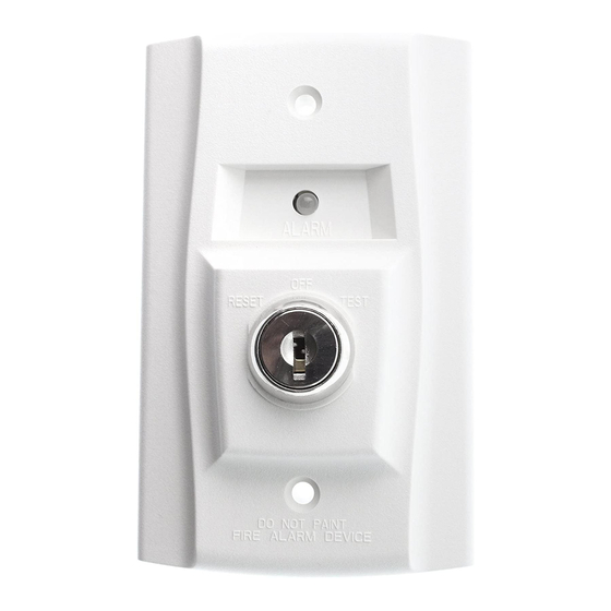
FIGURE 1. RTS151KEYA
FIGURE 2: WIRING DIAGRAM FOR RTS151KEYA TO D4120A
4-WIRE DUCT SMOKE DETECTOR:
RTS151KEYA
FIELD
2
INSTALLED
4
JUMPER
1
(RED LED)
ALARM
5
3
(GREEN LED)
POWER
6
* Sup. contacts cannot be used if they are wired to control panel.
FIGURE 3: WIRING DIAGRAM FOR RTS151KEYA TO D2A 2-WIRE
DUCT SMOKE DETECTOR:
TEST COIL +
TEST COIL –
COMM +
OUT (CONV ONLY) +
COMM –
RA/RTS –
RA +
RTS +
NOTE: THE RTS151KEYA TEST COIL
CIRCUIT REQUIRES AN EXTERNAL 24 VDC
POWER SUPPLY WHICH MUST BE UL LISTED.
NOTE: THE USE OF A REMOTE TEST STATION REQUIRES THE
INSTALLATION OF AN ACCESSORY COIL, PART NUMBER DCOIL,
SOLD SEPARATELY.
1
1-800-SENSOR2, FAX: 905-812-0771
www.systemsensor.ca
OFF
RESET
TEST
D4120A
AUX OUT +
AUX OUT –
ALARM
*
SUP, NO
R TEST
SUP, C
R RESET
*
4
5
EXTERNAL
(-) POWER (+)
SUPPLY
1
2
3
RTS151KEYA
REMOTE TEST STATION
LED OPTION
1 PER UNIT
10mA CURRENT DRAW
TEST COIL OPTION
1 PER UNIT
95mA CURRENT DRAW
I56-3475-000
H0195-01
H0582-13
H0571-10
Advertisement
Table of Contents

Related Manuals for System Sensor RTS151KEYA


Summary of Contents for System Sensor RTS151KEYA
- Page 1 H0582-13 should turn off. Then, turn the key back to the “NORMAL” position and re- move. The RTS151KEYA is capable of resetting only certain models of detec- FIGURE 3: WIRING DIAGRAM FOR RTS151KEYA TO D2A 2-WIRE tors. Refer to the detector installation instructions for additional information.
- Page 2 FIGURE 6. WIRING DIAGRAM FOR RTS151KEYA TO DH100 2-WIRE FIGURE 5. WIRING DIAGRAM FOR RTS151KEYA TO DH100ACDC DUCT SMOKE DETECTOR: 4-WIRE DUCT SMOKE DETECTOR: NOTE: Terminal 6 of the RTS151KEYA is not used when wired to a 2-wire detector. DH100ACDCLPA RTS151KEYA Alarm Signal...
Need help?
Do you have a question about the RTS151KEYA and is the answer not in the manual?
Questions and answers