Table of Contents
Advertisement
Quick Links
Advertisement
Table of Contents

Related Manuals for Supermicro SuperServer 5038MR-H8TRF


Summary of Contents for Supermicro SuperServer 5038MR-H8TRF
- Page 1 UPER ERVER ® 5038MR-H8TRF USER’S MANUAL Revision 1.0a...
- Page 2 This product, including software and documentation, is the property of Supermicro and/or its licensors, and is supplied only under a license. Any use or reproduction of this product is not allowed, except as expressly permitted by the terms of said license.
- Page 3 If you have any questions, please contact our support team at: support@supermicro.com This manual may be periodically updated without notice. Please check the Supermicro Web site for possible updates to the manual revision level. Warnings Special attention should be given to the following symbols used in this manual.
-
Page 4: Table Of Contents
Hard Drives ..................... 1-4 PCI Expansion Slots ..................1-4 User Interface ....................1-4 Cooling System ....................1-4 Contacting Supermicro ..................1-5 Chapter 2 Server Installation Unpacking the System ..................2-1 Preparing for Setup ..................2-1 Choosing a Setup Location ................2-1 Warnings and Precautions ................ - Page 5 Preface Control Panel LEDs ..................3-3 Power Fail ....................... 3-3 Node Status LEDs ..................3-3 Hard Drive Carrier LEDs ................. 3-4 Node Controls ....................3-5 Power Button and LED ................... 3-5 UID Button and LED ..................3-5 Failure LED ..................... 3-5 Power Supply LEDs ..................
- Page 6 UPER ERVER 5038MR-H8TRF User's Manual Rear Input/Output Panel ................5-11 Other Connectors ..................5-12 Jumper Settings .................... 5-15 Onboard Indicators ..................5-18 SATA Ports ....................5-19 5-10 Installing Software ..................5-20 SuperDoctor 5 ..................... 5-21 ® 5-11 Onboard Battery .................... 5-22 Chapter 6 Advanced Chassis Setup ............6-1 Overview ......................
- Page 7 Super Micro Computer, Inc. 980 Rock Ave. San Jose, CA 95131 U.S.A. Tel: +1 (408) 503-8000 Fax: +1 (408) 503-8008 Email: marketing@supermicro.com (General Information) support@supermicro.com (Technical Support) Web Site: www.supermicro.com Europe Address: Super Micro Computer B.V. Het Sterrenbeeld 28, 5215 ML...
- Page 8 UPER ERVER 5038MR-H8TRF User's Manual Notes...
-
Page 9: Chapter 1 Introduction
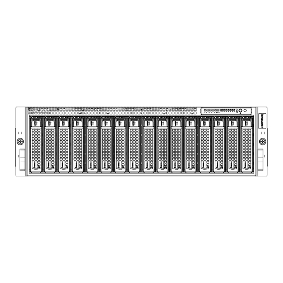
Chapter 1: Introduction Chapter 1 Introduction Overview The SuperServer 5038MR-H8TRF is a high-density multi-node server comprised of the SC938BH-R1620BP 3U server chassis and eight hot-pluggable computing nodes, each with an X10SRD-F single processor motherboard. Certified operating systems are listed at www.supermicro.com. -
Page 10: Serverboard Features
Figure 1-1 displays a block diagram of the chipset. Processors The serverboard supports a single Intel Xeon E5-2600/E5-1600 v3 series processor in LGA2011 sockets (Socket R3). Refer to the Supermicro web site for a complete listing of supported processors (www.supermicro.com). Memory The serverboard has four memory sockets that can support up to 256 GB RDIMM (Registered DIMMs) or LRDIMM. - Page 11 Chapter 1: Introduction CPU0 PROCESSOR Socket 00 QPI0 JPCIE1 QPI1 PCIE 3.0 x16 SATA GEN 3 USB 3.0 PCI-E x1 HEADER R,G,B KVM CONNECTOR DDR 3 RMII AST2400 IPMI LAN FLASH RTL8211E Figure 1-1. Intel PCH C612 Chipset: System Block Diagram Note: This is a general block diagram.
-
Page 12: Server Chassis Features
UPER ERVER 5038MR-H8TRF User's Manual Server Chassis Features The 5038MR-H8TRF is built upon the SC938BH-R1620BP chassis. Details and related procedures can be found in Chapter 6.The following is a general outline of the main features of the chassis. System Power The chassis features dual redundant 1620 W hot-plug power modules. -
Page 13: Contacting Supermicro
Super Micro Computer, Inc. 980 Rock Ave. San Jose, CA 95131 U.S.A. Tel: +1 (408) 503-8000 Fax: +1 (408) 503-8008 Email: marketing@supermicro.com (General Information) support@supermicro.com (Technical Support) Web Site: www.supermicro.com Europe Address: Super Micro Computer B.V. Het Sterrenbeeld 28, 5215 ML... - Page 14 UPER ERVER 5038MR-H8TRF User's Manual Notes...
-
Page 15: Chapter 2 Server Installation
Chapter 2: Server Installation Chapter 2 Server Installation This chapter provides instructions for preparing and mounting your chassis in a rack. Unpacking the System You should inspect the box the chassis was shipped in and note if it was damaged in any way. -
Page 16: Warnings And Precautions
UPER ERVER 5038MR-H8TRF User's Manual Warnings and Precautions Rack Precautions • Ensure that the leveling jacks on the bottom of the rack are fully extended to the floor with the full weight of the rack resting on them. • In single rack installation, stabilizers should be attached to the rack. In multiple rack installations, the racks should be coupled together. -
Page 17: Rack Mounting Considerations
Chapter 2: Server Installation Rack Mounting Considerations Ambient Operating Temperature If installed in a closed or multi-unit rack assembly, the ambient operating temperature of the rack environment may be greater than the ambient temperature of the room. Therefore, consideration should be given to installing the equipment in an environment compatible with the manufacturer’s maximum rated ambient temperature (Tmra). -
Page 18: Installing The System Into A Rack
UPER ERVER 5038MR-H8TRF User's Manual Installing the System into a Rack This section provides information on installing the server into a rack unit with the rack rails provided. There are a variety of rack units on the market, so the assembly procedure may differ slightly. -
Page 19: Releasing The Inner Rail
Chapter 2: Server Installation Releasing the Inner Rail Each inner rail has a locking latch. This latch prevents the server from coming completely out of the rack when when the chassis is pulled out for servicing. To mount the rail onto the chassis, first release the inner rail from the outer rails. Releasing Inner Rail from the Outer Rails 1. -
Page 20: Installing The Inner Rails On The Chassis
UPER ERVER 5038MR-H8TRF User's Manual Installing the Inner Rails on the Chassis Installing the Inner Rails 1. Identify the left and right inner rails. They are labeled. 2. Place the inner rail firmly against the side of the chassis, aligning the hooks on the side of the chassis with the holes in the inner rail. -
Page 21: Installing The Outer Rails Onto The Rack
Chapter 2: Server Installation Installing the Outer Rails onto the Rack Installing the Outer Rails 1. Press upward on the locking tab at the rear end of the middle rail. 2. Push the middle rail back into the outer rail. 3. -
Page 22: Sliding The Chassis Onto The Rack Rails
UPER ERVER 5038MR-H8TRF User's Manual Sliding the Chassis onto the Rack Rails Warning: Mounting the system into the rack requires at least two people to support the chassis during installation. Please follow safety recommendations printed on the rails. Installing the Chassis into a Rack 1. -
Page 23: Chapter 3 System Interface
Chapter 3: System Interface Chapter 3 System Interface Overview The server includes a control panel on the front that houses the chassis power buttons and status monitoring lights. Each node has a power button and status lights on the rear. There are status lights on each of the hard drives, and status lights for the power supply visible from the back of the chassis. -
Page 24: Control Panel Buttons
SuperServer 5038MR-H8TRF User's Manual Control Panel Buttons The chassis includes two push-buttons that control power to the system. Power The main power switch is used to apply or remove power from the power supply to the server system. Turning off system power with this button removes the main power but keeps standby power supplied to the system. -
Page 25: Control Panel Leds
Chapter 3: System Interface Control Panel LEDs There are LEDs that provide status information about the system. Power Fail This red LED is illuminated when one of the power supplies fails while any node is powered on. It is off during normal operation. Node Status LEDs The control panel features eight numbered node status LEDs, which indicate the status of each serverboard node. -
Page 26: Hard Drive Carrier Leds
SuperServer 5038MR-H8TRF User's Manual Drive Carrier LEDs The chassis includes externally accessible SAS/SATA drives. Each drive carrier displays two status LEDs on the front of the carrier. Hard Drive Carrier LEDs Figure 3-2. Hard Drive Carrier LEDs LED Color Blinking Pattern... -
Page 27: Node Controls
Chapter 3: System Interface Node Controls Status LEDs Individual LEDS are located on the back of each serverboard node on the rear of the chassis. Power Button and LED (Green) UID Button and LED (Blue) Failure LED (Red) Figure 3-3. Rear Node LED Indicators Power Button and LED This button will power on the node individually. -
Page 28: Power Supply Leds
SuperServer 5038MR-H8TRF User's Manual Failure LED This LED is illuminated red when a failure has occurred and off during normal operation. If illuminated, check that the two corresponding hard drives are fully inserted into their bays with their handles completely pushed in. Check also that the fan is operating properly and that the node is fully inserted into its bay. -
Page 29: Chapter 4 Standardized Warning Statements For Ac Systems
The following statements are industry standard warnings, provided to warn the user of situations which have the potential for bodily injury. Should you have questions or experience difficulty, contact Supermicro's Technical Support department for assistance. Only certified technicians should attempt to install or configure components. - Page 30 UPER ERVER 5038MR-H8TRF User's Manual Warnung WICHTIGE SICHERHEITSHINWEISE Dieses Warnsymbol bedeutet Gefahr. Sie befinden sich in einer Situation, die zu Verletzungen führen kann. Machen Sie sich vor der Arbeit mit Geräten mit den Gefahren elektrischer Schaltungen und den üblichen Verfahren zur Vorbeugung vor Unfällen vertraut.
- Page 31 Warning Statements for AC Systems . ٌ ا ك ً ف حالة و ٌ يك أى تتسبب ف اصابة جسذ ة ٌ هذا الزهز ع ٌ خطز !تحذ ز قبل أى تعول عىل أي هعذات،يك عىل علن بالوخاطز ال ا ٌجوة عي الذوائز ٍ...
-
Page 32: Installation Instructions
UPER ERVER 5038MR-H8TRF User's Manual Installation Instructions Warning! Read the installation instructions before connecting the system to the power source. 設置手順書 システムを電源に接続する前に、 設置手順書をお読み下さい。 警告 将此系统连接电源前,请先阅读安装说明。 警告 將系統與電源連接前,請先閱讀安裝說明。 Warnung Vor dem Anschließen des Systems an die Stromquelle die Installationsanweisungen lesen. ¡Advertencia! Lea las instrucciones de instalación antes de conectar el sistema a la red de alimentación. -
Page 33: Circuit Breaker
Chapter 4: Warning Statements for AC Systems Circuit Breaker Warning! This product relies on the building's installation for short-circuit (overcurrent) protection. Ensure that the protective device is rated not greater than: 250 V, 20 A. サーキッ ト ・ ブレーカー この製品は、 短絡 (過電流) 保護装置がある建物での設置を前提としています。 保護装置の定格が250 V、... -
Page 34: Power Disconnection Warning
UPER ERVER 5038MR-H8TRF User's Manual هذا املنتج يعتمد عىل معداث الحاميت مه الدوائ ر القصرية التي تم تثبيتها يف املبنى 20A, 250V : تأكد من أن تقييم الجهاز الوقايئ ليس أكرث من 경고! 이 제품은 전원의 단락(과전류)방지에 대해서 전적으로 건물의 관련 설비에 의존합니다. - Page 35 Chapter 4: Warning Statements for AC Systems ¡Advertencia! El sistema debe ser disconnected de todas las fuentes de energía y del cable eléctrico quitado de los módulos de fuente de alimentación antes de tener acceso el interior del chasis para instalar o para quitar componentes de sistema. Attention Le système doit être débranché...
-
Page 36: Equipment Installation
UPER ERVER 5038MR-H8TRF User's Manual Equipment Installation Warning! Only trained and qualified personnel should be allowed to install, replace, or service this equipment. 機器の設置 トレーニングを受け認定された人だけがこの装置の設置、 交換、 またはサービスを許可 されています。 警告 只有经过培训且具有资格的人员才能进行此设备的安装、更换和维修。 警告 只有經過受訓且具資格人員才可安裝、更換與維修此設備。 Warnung Das Installieren, Ersetzen oder Bedienen dieser Ausrüstung sollte nur geschultem, qualifiziertem Personal gestattet werden. -
Page 37: Restricted Area
Chapter 4: Warning Statements for AC Systems Waarschuwing Deze apparatuur mag alleen worden geïnstalleerd, vervangen of hersteld door geschoold en gekwalificeerd personeel. Restricted Area Warning! This unit is intended for installation in restricted access areas. A restricted access area can be accessed only through the use of a special tool, lock and key, or other means of security. -
Page 38: Battery Handling
UPER ERVER 5038MR-H8TRF User's Manual אזור עם גישה מוגבלת !אזהרה יש להתקין את היחידה באזורים שיש בהם הגבלת גישה. הגישה ניתנת בעזרת (.'כלי אבטחה בלבד (מפתח, מנעול וכד . تخصيص هذه انىحذة نترك ب ُها ف مناطق محظورة تم ، م َ كن انىصىل إن منطقت محظورة فقط من خالل استخذاو أداة خاصت أو... - Page 39 Chapter 4: Warning Statements for AC Systems Warnung Bei Einsetzen einer falschen Batterie besteht Explosionsgefahr. Ersetzen Sie die Batterie nur durch den gleichen oder vom Hersteller empfohlenen Batterietyp. Entsorgen Sie die benutzten Batterien nach den Anweisungen des Herstellers. Attention Danger d'explosion si la pile n'est pas remplacée correctement. Ne la remplacer que par une pile de type semblable ou équivalent, recommandée par le fabricant.
-
Page 40: Redundant Power Supplies (If Applicable To Your System)
UPER ERVER 5038MR-H8TRF User's Manual Redundant Power Supplies Warning! This unit might have more than one power supply connection. All connections must be removed to de-energize the unit. 冗長電源装置 このユニッ トは複数の電源装置が接続されている場合があります。 ユニッ トの電源を切るためには、 すべての接続を取り外さなければなりません。 警告 此部件连接的电源可能不止一个,必须将所有电源断开才能停止给该部件供电。 警告 此裝置連接的電源可能不只一個,必須切斷所有電源才能停止對該裝置的供電。 Warnung Dieses Gerät kann mehr als eine Stromzufuhr haben. Um sicherzustellen, dass der Einheit kein trom zugeführt wird, müssen alle Verbindungen entfernt werden. -
Page 41: Backplane Voltage (If Applicable To Your System)
Chapter 4: Warning Statements for AC Systems . قد يكون لهذا الجهاز عدة اتصاالت بوحدات امداد الطاقة يجب إ ز الة كافة االتصاالت لعسل الوحدة عن الكهرباء 경고! 이 장치에는 한 개 이상의 전원 공급 단자가 연결되어 있을 수 있습니다. 이 장치에 전원을... -
Page 42: Comply With Local And National Electrical Codes
UPER ERVER 5038MR-H8TRF User's Manual מתח בפנל האחורי !אזהרה קיימת סכנת מתח בפנל האחורי בזמן תפעול המערכת. יש להיזהר במהלך .העבודה هناك خطز مه التيار الكهزبايئ أوالطاقة املىجىدة عىل اللىحة عندما يكىن النظام يعمل كه حذ ر ا عند خدمة هذا الجهاس 경고! 시스템이... -
Page 43: Product Disposal
Chapter 4: Warning Statements for AC Systems Attention L'équipement doit être installé conformément aux normes électriques nationales et locales. תיאום חוקי החשמל הארצי !אזהרה .התקנת הציוד חייבת להיות תואמת לחוקי החשמל המקומיים והארציים تركيب املعدات الكهربائية يجب أن ميتثل للقىاويه املحلية والىطىية املتعلقة بالكهرباء... -
Page 44: Hot Swap Fan Warning (If Applicable To Your System)
UPER ERVER 5038MR-H8TRF User's Manual Attention La mise au rebut ou le recyclage de ce produit sont généralement soumis à des lois et/ou directives de respect de l'environnement. Renseignez-vous auprès de l'organisme compétent. סילוק המוצר !אזהרה .סילוק סופי של מוצר זה חייב להיות בהתאם להנחיות וחוקי המדינה التخلص... - Page 45 Chapter 4: Warning Statements for AC Systems Warnung Gefährlich Bewegende Teile. Von den bewegenden Lüfterblätter fern halten. Die Lüfter drehen sich u. U. noch, wenn die Lüfterbaugruppe aus dem Chassis genommen wird. Halten Sie Finger, Schraubendreher und andere Gegenstände von den Öffnungen des Lüftergehäuses entfernt. ¡Advertencia! Riesgo de piezas móviles.
-
Page 46: Power Cable And Ac Adapter
Verbindungskabeln, Stromkabeln und/oder Adapater, die Ihre örtlichen Sicherheitsstandards einhalten. Der Gebrauch von anderen Kabeln und Adapter können Fehlfunktionen oder Feuer verursachen. Die Richtlinien untersagen das Nutzen von UL oder CAS zertifizierten Kabeln (mit UL/CSA gekennzeichnet), an Geräten oder Produkten die nicht mit Supermicro gekennzeichnet sind. 4-18... - Page 47 -בכבלים המוסמכים בUL -או בCSA (( כאשר מופיע עליהם קוד שלUL/CSA עבור כל מוצר חשמלי אחר, אלא רק במוצר אשר הותאם ע"יSupermicro .בלבד عند تركيب املنتج، قم باستخدام التوصيالت املتوفرة أو املحددة أو قم ب رش اء الكابالت الكهربائية ومحوالت التيار...
- Page 48 Het gebruik van niet geschikte Kabels en/of Adapters kan een storing of brand veroorzaken. Wetgeving voor Elektrische apparatuur en Materiaalveiligheid verbied het gebruik van UL of CSA -gecertificeerde Kabels (met UL/CSA in de code) voor elke andere toepassing dan de door Supermicro hiervoor beoogde Producten. 4-20...
-
Page 49: Chapter 5 Advanced Serverboard Setup
Chapter 5: Advanced Serverboard Setup Chapter 5 Advanced Serverboard Setup This chapter covers the steps required to install processors and heatsinks to the X10SRD-F serverboard, connect the data and power cables and install add-on cards. All serverboard jumpers and connections are described and a layout and quick reference chart are included in this chapter. -
Page 50: Installing The Processor And Heatsink
• Install the processor into the CPU socket before installing the heatsink. • Refer to the Supermicro web site for updates on CPU support. Installing an LGA 2011 Processor Installing a CPU 1. There are two levers on the LGA 2011 socket. - Page 51 Chapter 5: Advanced Serverboard Setup 3. W ith the sec ond lever f ully Open the load plate. retracted, gently push down on the "Open 1st" lever to loosen the load plate. Lift the load plate with your fingers to open it completely. 4.
- Page 52 UPER ERVER 5038MR-H8TRF User's Manual Gently close the load plate. 7. With the "Close 1st" lever fully retracted, gently close the load plate. Push down and lock the lever labeled "Close 1st". 8. Make sure the locking mechanism on the "Close 1st" lever catches the lip of the load plate.
-
Page 53: Installing A Cpu Heatsink
Chapter 5: Advanced Serverboard Setup Installing a CPU Heatsink Installing a Heatsink 1. Place the heatsink on top of the CPU so that the four mounting holes are aligned with those on the retention mechanism. 2. Screw in two diagonal screws (#1 and #2) until just snug—do not over-tighten and damage the CPU. -
Page 54: Input/Output Ports
UPER ERVER 5038MR-H8TRF User's Manual Input/Output Ports The I/O ports at the rear of the server are pictured below. Figure 5-2. Rear Panel I/O Ports 1. KVM Port 2. IPMI dedicated LAN 3. Power Button and LED 4. UID Button... -
Page 55: Installing Memory
The X10SRD-F supports up to 256 GB of DDR4 ECC LRDIMM and RDIMM at 1333/1600/2133 MHz in four DIMM slots. For best performance, install memory modules of the same type and same speed in the slots as indicated. For the latest memory updates, refer to the Supermicro website at www.supermicro.com/products/ motherboard. - Page 56 USB0/1 JUIDB1 UPER ERVER 5038MR-H8TRF User's Manual JSTBY1 JIPMB1 IPMI_LAN JPG1 JUSB2 USB1(3.0) JPB1 LEDM1 X10SRD-F REV: 1.00 DESIGNED IN USA JSD1 JPF1 JPF2 JBR1 JVRM2 JVRM1 JWD1 I-SATA5 JBT1 I-SATA4 JPME2 JTPM1 DIMMA1 DIMMC1 DIMMB1 DIMMD1 S-SGPIO1 FAN1 S-SATA/SAS0 S-SATA/SAS1 Figure 5-3.
-
Page 57: Serverboard Details
Chapter 5: Advanced Serverboard Setup Serverboard Details JUIDB1 JKVM1 IPMI LAN USB0/1 LED1 LED2 USB0/1 JUIDB1 JIPMB1 JSTBY1 JSTBY1 JIPMB1 JPB1 IPMI_LAN JUSB2 - USB1 JI2C1 JPG1 JUSB2 JPG1 USB1(3.0) JI2C2 JPCIE1 JPB1 LEDM1 MICRO LP LEDM1 JPCIE2 X10SRD-F REV: 1.00 DESIGNED IN USA JSD1... - Page 58 UPER ERVER 5038MR-H8TRF User's Manual Connectors Description Onboard Battery LGA 2011 Socket for a single Intel Xeon E5-2600/E5-1600 v3 series FAN1 System Fan Header IPMI_LAN IPMI Dedicated LAN Port I-SATA4, I-SATA5 SATA 3.0 Ports supported by Intel PCH JIPMB1 System Management Bus Header for the IPMI Slot JPCIE1 MicroLP PCI-E 3.0 X8 Slot JPCIE2...
-
Page 59: Connector Definitions
Chapter 5: Advanced Serverboard Setup Connector Definitions Power Connectors The X10SRD-F motherboard is powered through the slide-in connection at the front of the board. No connecting cables are necessary. Rear Input/Output Panel KVM Port The KVM port supports two USB, VGA and UART interface. Attach a compatible KVM connector to this port. -
Page 60: Other Connectors
UPER ERVER 5038MR-H8TRF User's Manual Other Connectors Universal Serial Bus (USB) One USB 3.0 header (USB1) is located the on the motherboard. There are also two ports (USB 0/1) available through the KVM port. (Cables are not included.) See the table on the right for pin definitions. - Page 61 Chapter 5: Advanced Serverboard Setup Fan Header Fan Header Pin Definitions This motherboard has one system fan Pin# Definition header (FAN1). This 4-pin fan header Ground is backward compatible with the +12V traditional 3-pin fan headers. However, Tachometer fan speed control is available for Pulse Width Modulation 4-pin fans only.
- Page 62 Definition located at JSD1 and JSD2. These connectors are used with Supermciro Ground SuperDOMs to provide backward- Ground compatible power support to non- Supermicro SATADOMs that require external power supply. Unit Identifier Buttons/UID LED UID Button Indicators Pin# Definition A rear unit identifier button (JUIDB2) Ground is located next to the COM port.
-
Page 63: Jumper Settings
Chapter 5: Advanced Serverboard Setup Jumper Settings Explanation of Jumpers To modify the operation of the serverboard, jumpers can be used Connector to choose between optional settings. Pins Jumpers create shorts between two pins to change the function of the Jumper connector. - Page 64 UPER ERVER 5038MR-H8TRF User's Manual VGA Enable VGA Enable/Disable Jumper Settings JPG1 allows the user to enable the (JPG1) onboard VGA connector (through Pin# Definition the KVM). Close Pins 1-2 to use Enabled (Default) this function. The default setting is Disabled Enabled.
- Page 65 Chapter 5: Advanced Serverboard Setup SMB (I C) Bus to PCI Slots C to PCI Slots Jumper Settings Jumpers JI C1 and JI C2 allow you Pin# Definition to connect the System Management Enabled Bus (SMB) to PCI-E and PCI slots. Disabled (Default) The default setting is set to Disabled.
-
Page 66: Onboard Indicators
UPER ERVER 5038MR-H8TRF User's Manual Onboard Indicators IPMI LAN Speed LED IPMI Dedicated LAN Port LED Color Definition A dedicated IPMI LAN port is located 10 Mbps, or No Connection on the rear I/O panel. The amber Green 100 Mbps LED on the right indicates activity, Amber 1 Gbps... -
Page 67: Sata Ports
Chapter 5: Advanced Serverboard Setup SATA Ports Two SATA 3.0 connectors (I-SATA4, I-SATA5) and two SAS 3.0 connectors (SAS0, SAS1) are located on the motherboard to provide Serial Link connections. I-SATA ports are supported by the Intel PCH C612 chipset, and SAS ports are supported by the Intel SCU chip. -
Page 68: 5-10 Installing Software
UPER ERVER 5038MR-H8TRF User's Manual 5-10 Installing Software The Supermicro ftp site contains drivers and utilities for your system at ftp://ftp. supermicro.com. Some of these must be installed, such as the chipset driver. After accessing the ftp site, go into the CDR_Images directory and locate the ISO file for your serverboard. -
Page 69: Superdoctor ® 5
Chapter 5: Advanced Serverboard Setup SuperDoctor ® The Supermicro SuperDoctor 5 is a hardware and operating system services monitoring program that functions in a command-line or web-based interface in Windows and Linux operating systems. The program monitors system health information such as CPU temperature, system voltages, system power consumption, fan speed, and provides alerts via email or Simple Network Management Protocol (SNMP). -
Page 70: 5-11 Onboard Battery
Figure 5-8. SuperDoctor 5 Interface Display Screen (Remote Control) Note: The SuperDoctor 5 program and User’s Manual can be downloaded from the Supermicro web site at http://www.supermicro.com/products/nfo/sms_sd5.cfm. For Linux, we recommend that you use the SuperDoctor II application instead. 5-11 Onboard Battery Please handle used batteries carefully. - Page 71 Chapter 5: Advanced Serverboard Setup Notes 5-23...
-
Page 72: Chapter 6 Advanced Chassis Setup
Chapter 6: Advanced Chassis Setup Chapter 6 Advanced Chassis Setup Overview This chapter covers the steps required to install components and perform maintenance on the chassis. The only tool required is a Phillips screwdriver. Review the warnings and precautions listed in the manual before setting up or servicing this chassis. -
Page 73: Removing Power From The System
UPER ERVER 5038MR-H8TRF User's Manual Removing Power from the System Before performing most setup or maintenance tasks, use the following procedure to ensure that power has been removed from the system. 1. Use the operating system to power down the system, following the on-screen prompts. -
Page 74: Removing The Chassis Cover
Chapter 6: Advanced Chassis Setup Removing the Chassis Cover Remove Three Screws Remove Film From Vents Figure 6-3. Removing the Chassis Cover IMPORTANT: Before operating the system for the first time, remove the protective film covering the ventilation openings on the top of the chassis. These vents provide proper ventilation and cooling for the system. -
Page 75: Corresponding Nodes, Fans And Hard Drives
UPER ERVER 5038MR-H8TRF User's Manual Corresponding Nodes, Fans and Hard Drives The chassis contains eight individual motherboards contained in separate nodes. Each node controls two hard drives and shares a fan with the node beside it. Note that if a node is pulled out of the chassis, the hard drives associated with that node will power-down. -
Page 76: Removing Motherboard Nodes
Chapter 6: Advanced Chassis Setup Removing Motherboard Nodes The chassis comes equipped with eight removable nodes, each one containing an individual motherboard. Removing these nodes will also power-down the corresponding hard drives. See the table in Section 6-4 to determine which hard drives are controlled by each node. -
Page 77: Installing Hard Drives
UPER ERVER 5038MR-H8TRF User's Manual Installing Hard Drives The chassis features sixteen hot-swappable hard drives. These hard drives are contained in drive carriers and may be removed without powering-down the system. Removing Hard Drive Carriers from the Chassis 1. Press the release button on the drive carrier, which will extend the drive carrier handle. - Page 78 Chapter 6: Advanced Chassis Setup Dummy Drive Drive Carrier Figure 6-7. Removing a Dummy Drive from the Drive Carrier The hard drives are mounted in drive carriers to simplify their installation and removal from the chassis. These carriers also help promote proper airflow through the drive bays.
- Page 79 5. Secure the drive carrier into the drive bay by closing the drive carrier handle Note: Enterprise level hard disk drives are recommended for use in Supermicro servers. For information on recommended HDDs, visit the Supermicro Web site at...
-
Page 80: Installing An Air Shroud
Chapter 6: Advanced Chassis Setup Installing an Air Shroud Air shrouds concentrate airflow to maximize fan efficiency. Use an air shroud for each node. Make sure that the expansion card (if present) and all components are installed in each node before installing the air shroud. Installing the Air Shroud •... -
Page 81: System Fans
UPER ERVER 5038MR-H8TRF User's Manual System Fans Four 8-cm fans circulate air through the chassis to lower the internal temperature. The system fans are designed to be easily changed, with no tools required and no need to remove any other parts inside the chassis. See Section 6-4 to determine which nodes and hard drives are cooled by each system fan. -
Page 82: Power Supply
The Power Fail LED will illuminate and remain on until the failed unit has been replaced. Replacement units can be ordered directly from Supermicro. The power supply units have a hot-plug capability, meaning you can replace the failed unit without powering down the system. - Page 83 UPER ERVER 5038MR-H8TRF User's Manual Changing the Power Supply 1. Unplug the AC power cord from the failed power supply. The system can continue running. 2. Press the release tab at the top of the power supply. 3. Push and hold the release tab on the back of the power supply. 4.
-
Page 84: 6-10 Removing And Installing The Backplane
Chapter 6: Advanced Chassis Setup 6-10 Removing and Installing the Backplane The backplane is attached to the fan bracket, which is located in the midsection of the chassis. In the unlikely event of a backplane failure, follow the instructions below to replace it. Removing the Backplane and Fan Bracket Assembly Removing the Backplane and Fan Bracket from the Chassis 1. - Page 85 UPER ERVER 5038MR-H8TRF User's Manual Figure 6-7. Removing the Backplane from the Fan Bracket Removing the Backplane from the Fan Bracket Removing the Backplane 1. Remove the eight screws securing the two side mounting brackets to the sides of the fan bracket and set them aside for later use. Remove the side mounting brackets.
- Page 86 Chapter 6: Advanced Chassis Setup Figure 6-8. Installing the Backplane onto the Fan Bracket Installing the Backplane onto the Fan Bracket Installing the Backplane 1. Ensure that all power has been disconnected from the chassis. 2. Hold the backplane by its edges and carefully place it against the fan mounting bracket, aligning the mounting holes in the backplane with those in the fan bracket.
- Page 87 UPER ERVER 5038MR-H8TRF User's Manual Figure 6-9. Installing the Backplane and Fan Bracket Installing the Backplane and Fan Bracket Assembly Installing the Backplane and Fan Bracket 1. Ensure that the chassis has been disconnected from any power source. 2. Reconnect the wiring to the backplane. 3.
-
Page 88: Chapter 7 Bios
AMI BIOS setup utility. This setup utility can be accessed by pressing <Delete> at the appropriate time during system boot. Note: For AMI UEFI BIOS Recovery, please refer to the UEFI BIOS Recovery User Guide posted @ http://www.supermicro.com/support/manuals/. -
Page 89: Main Setup
SuperServer 5038MR-H8TRF User’s Manual Starting the Setup Utility Normally, the only visible Power-On Self-Test (POST) routine is the memory test. As the memory is being tested, press the <Delete> key to enter the main menu of the AMI BIOS setup utility. From the main menu, you can access the other setup screens. - Page 90 Chapter 7: AMI BIOS System Time This item displays the system time in HH:MM:SS format (e.g. 15:32:52). Supermicro X10SRD-F BIOS Version This item displays the version of the BIOS ROM used in this system. Build Date This item displays the date that the BIOS setup utility was built.
-
Page 91: Advanced Setup Configurations
SuperServer 5038MR-H8TRF User’s Manual Advanced Setup Configurations Use the arrow keys to select Boot Setup and hit <Enter> to access the submenu items: Caution: Take caution when changing the Advanced settings. An incorrect value, a very high DRAM frequency or incorrect DRAM timing may cause system to become unstable. - Page 92 Chapter 7: AMI BIOS Wait For 'F1' If Error This forces the system to wait until the 'F1' key is pressed if an error occurs. The options are Disabled and Enabled. Interrupt 19 Capture Interrupt 19 is the software interrupt that handles the boot disk function. When this item is set to Enabled, the ROM BIOS of the host adaptors will "capture"...
- Page 93 SuperServer 5038MR-H8TRF User’s Manual CPU Configuration The following CPU information will be displayed: • Processor Socket • Processor ID • Processor Frequency • Processor Max Ratio • Processor Min Ratio • Microcode Revision • L1 Cache RAM • L2 Cache RAM •...
- Page 94 Chapter 7: AMI BIOS PPIN Control Select Unlock/Enable to use the Protected-Processor Inventory Number (PPIN) in the system. The options are Unlock/Enable and Unlock/Disable. Hardware Prefetcher (Available when supported by the CPU) If set to Enabled, the hardware prefetcher will prefetch streams of data and instruc- tions from the main memory to the L2 cache to improve CPU performance.
- Page 95 SuperServer 5038MR-H8TRF User’s Manual Advanced Power Management Configuration Power Technology Select Energy Efficient to support power-saving mode. Select Custom to custom- ize system power settings. Select Disabled to disable power-saving settings. The options are Disable, Energy Efficient, and Custom. *If the item above is set to "Custom," CPU P State/C State/T State will display:...
- Page 96 Chapter 7: AMI BIOS CPU C State Control Package C State Limit Use this item to set the limit on the C-State package register. The options are C0/1 state, C2 state, C6 (non-Retention) state, and C6 (Retention) state. CPU C3 Report Select Enable to allow the BIOS to report the CPU C3 State (ACPI C2) to the operating system.
- Page 97 SuperServer 5038MR-H8TRF User’s Manual When this feature is set to Enable, the EV_DFX Lock Bits that are located on a processor will always remain clear during electric tuning. The options are Dis- able and Enable. IIO1 Configuration CPU1 MICRO-LP PCI-E 3.0 X8 SLOT Link Speed Use this item to configure the link speed of a PCI-E port specified by the user.
- Page 98 Chapter 7: AMI BIOS Monitor) through the DMAR ACPI Tables. This feature offers fully-protected I/O resource sharing across Intel platforms, providing greater reliability, security and availability in networking and data-sharing. The options are Enable and Disable. Interrupt Remapping Select Enable for Interrupt Remapping support to enhance system performance. The options are Enable and Disable.
- Page 99 SuperServer 5038MR-H8TRF User’s Manual Memory Frequency Use this feature to set the maximum memory frequency for onboard memory modules. The options are Auto, 1333, 1400, 1600, 1800, 1867, 2000, 2133, 2200, 2400, 2600, 2667, and Reserved (Do not select Reserved).
- Page 100 Chapter 7: AMI BIOS Memory RAS (Reliability Availability Serviceability) Configuration Use this submenu to configure the following Memory RAS settings. RAS Mode Select Enable to enable RAS support to enhance reliability, availability and ser- viceability of onboard memory modules. The options are Enable and Disable. Memory Rank Sparing This item indicates if memory rank sparing is supported by the motherboard.
- Page 101 SuperServer 5038MR-H8TRF User’s Manual South Bridge Configuration The following South Bridge information will display: • USB Configuration • USB Module Version • USB Devices Legacy USB Support This feature enables support for legacy USB devices. Select Auto to disable legacy support if USB devices are not present. Select Disabled to have USB devices available only for EFI applications.
- Page 102 Chapter 7: AMI BIOS EHCI2 Select Enabled to enable EHCI (Enhanced Host Controller Interface) support on USB 2.0 connector #2 (at least one USB 2.0 connector should be enabled for EHCI support.) The options are Disabled and Enabled. XHCI Pre-Boot Driver Select Enabled to enable XHCI (Extensible Host Controller Interface) support on a pre-boot drive specified by the user.
- Page 103 SuperServer 5038MR-H8TRF User’s Manual Port 0~ Port 5 Select Enabled to enable a SATA port specified by the user. The options are Dis- abled and Enabled. Port 0 ~ Port 5 Hot Plug This feature designates the port specified for hot plugging. Set this item to Enabled for hot-plugging support, which will allow the user to replace a SATA disk drive without shutting down the system.
- Page 104 Chapter 7: AMI BIOS Serial ATA Port 0~ Port 5 This item displays the information detected on the installed SATA drives on the particular SATA port. • Model number of drive and capacity • Software Preserve Support Port 0~ Port 5 Select Enabled to enable a SATA port specified by the user.
- Page 105 SuperServer 5038MR-H8TRF User’s Manual • Current State • Error Code PCIe/PCI/PnP Configuration The following PCI information will be displayed: • PCI Bus Driver Version • PCI Devices Common Settings: PCI PERR/SERR Support Select Enabled to allow a PCI device to generate a PERR/SERR number for a PCI Bus Signal Error Event.
- Page 106 Chapter 7: AMI BIOS MMIOHBase Use this item to select the base memory size according to memory-address map- ping for the IO hub. The base memory size must be between 4032G to 4078G. The options are 56T, 48T, 24T, 512G, and 256G.\ MMIO High Size Use this item to select the high memory size according to memory-address mapping for the IO hub.
- Page 107 SuperServer 5038MR-H8TRF User’s Manual Change Port 1 Settings/Change Port 2 Settings This feature specifies the base I/O port address and the Interrupt Request address of Serial Port 1or Serial Port 2. Select Auto for the BIOS to automatically assign the base I/O and IRQ address to a serial port specified.
- Page 108 Chapter 7: AMI BIOS Data Bits Use this feature to set the data transmission size for Console Redirection. The options are 7 (Bits) and 8 (Bits). Parity A parity bit can be sent along with regular data bits to detect data transmission errors.
- Page 109 SuperServer 5038MR-H8TRF User’s Manual Putty KeyPad This feature selects Function Keys and KeyPad settings for Putty, which is a terminal emulator designed for the Windows OS. The options are VT100, LINUX, XTERMR6, SCO, ESCN, and VT400. Redirection After BIOS Post Use this feature to enable or disable legacy Console Redirection after BIOS POST.
- Page 110 Chapter 7: AMI BIOS Parity A parity bit can be sent along with regular data bits to detect data transmission errors. Select Even if the parity bit is set to 0, and the number of 1's in data bits is even. Select Odd if the parity bit is set to 0, and the number of 1's in data bits is odd.
- Page 111 SuperServer 5038MR-H8TRF User’s Manual Redirection After BIOS Post Use this feature to enable or disable legacy Console Redirection after BIOS POST. When set to Bootloader, legacy Console Redirection is disabled before booting the OS. When set to Always Enable, legacy Console Redirection remains enabled when booting the OS.
- Page 112 Chapter 7: AMI BIOS Flow Control Use this item to set the flow control for Console Redirection to prevent data loss caused by buffer overflow. Send a "Stop" signal to stop sending data when the receiving buffer is full. Send a "Start" signal to start sending data when the receiving buffer is empty.
-
Page 113: Event Logs
SuperServer 5038MR-H8TRF User’s Manual Event Logs Use this feature to configure Event Log settings. Change SMBIOS Event Log Settings SMBIOS Event Log Change this item to enable or disable all features of the Smbios Event Logging during boot. The options are Enabled and Disabled. - Page 114 Chapter 7: AMI BIOS When Log is Full Select Erase Immediately to immediately erase all errors in the SMBIOS event log when the event log is full. Select Do Nothing for the system to do nothing when the SMBIOS event log is full. The options are Do Nothing and Erase Immediately. SMBIOS Event Log Standard Settings Log System Boot Event Select Enabled to log system boot events.
-
Page 115: Ipmi Settings
SuperServer 5038MR-H8TRF User’s Manual IPMI Settings Use this feature to configure the Intelligent Platform Management Interface(IPMI) settings. IPMI Firmware Revision This item indicates the IPMI firmware revision used in your system. IPMI Status This item indicates the status of the IPMI firmware installed in your system. - Page 116 Chapter 7: AMI BIOS Select No to keep all system event logs after each system reboot. The options are No, Yes, On next reset, and Yes, On every reset. When SEL is Full This feature allows the user to determine what the BIOS should do when the sys- tem event log is full.
-
Page 117: Security
SuperServer 5038MR-H8TRF User’s Manual Subnet Mask Subnet masks tell the network which subnet this machine belongs to. The value of each three-digit number separated by dots should not exceed 255. Station MAC Address MAC addresses are 6 two-digit hexadecimal numbers (Base 16, 0 ~ 9, A, B, C, D, E, F) separated by dots (i.e., 00.30.48.D0.D4.60). - Page 118 Chapter 7: AMI BIOS Secure Boot Menu This section displays the contents of the following secure boot features: • System Mode • Secure Boot Secure Boot Use this item to enable secure boot. The options are Disabled and Enabled. Secure Boot Mode Use this item to select the secure boot mode.
- Page 119 SuperServer 5038MR-H8TRF User’s Manual Key Exchange Key (KEK) This feature allows the user to configure the settings of the key exchange keys. Set New KEK Select Yes to load the KEK from the manufacturer's defaults. Select No to load the KEK from a file.
-
Page 120: Boot
Chapter 7: AMI BIOS Append DBX Select Yes to add the DBX from the manufacturer's defaults to the existing DBX. Select No to load the DBX from a file. The options are Yes and No. Boot Use this feature to configure Boot Settings: Boot Configuration Setup Prompt Timeout Use this item to indicate the length of time (the number of seconds) for the BIOS to... - Page 121 SuperServer 5038MR-H8TRF User’s Manual • Dual Boot Order #3 • Dual Boot Order #4 • Dual Boot Order #5 • Dual Boot Order #6 • Dual Boot Order #7 • Dual Boot Order #8 • Dual Boot Order #9 •...
-
Page 122: Save & Exit
Chapter 7: AMI BIOS Save & Exit Select the Exit tab from the BIOS Setup Utility screen to enter the Exit BIOS Setup screen. Discard Changes and Exit Select this option to quit the BIOS Setup without making any permanent changes to the system configuration, and reboot the computer. - Page 123 SuperServer 5038MR-H8TRF User’s Manual Restore Optimized Defaults To set this feature, select Restore Defaults from the Exit menu and press <Enter>. These are factory settings designed for maximum system stability, but not for maximum performance. Save As User Defaults To set this feature, select Save as User Defaults from the Exit menu and press <En- ter>.
-
Page 124: Appendix A Bios Error Beep Codes
Appendix A: BIOS Error Beep Codes Appendix A BIOS Error Beep Codes During the POST (Power-On Self-Test) routines, which are performed at each system boot, errors may occur. Non-fatal errors are those which, in most cases, allow the system to continue to boot. - Page 125 UPER ERVER 5038MR-H8TRF User's Manual Notes...
- Page 126 Flashing the wrong BIOS can cause irreparable damage to the system. In no event shall Supermicro be liable for direct, indirect, special, incidental, or consequential damages arising from a BIOS update. If you need to update the BIOS, do not shut down or reset the system while the BIOS is updating to avoid possible boot failure.
- Page 127 Root "\" Directory of a USB device or a writeable CD/DVD. Note: If you cannot locate the "Super.ROM" file in your driver disk, visit our website at www.supermicro.com to download the BIOS image into a USB flash device and rename it "Super.ROM" for BIOS recovery use.
- Page 128 Appendix B: System Specifications 4. After locating the new BIOS binary image, the system will enter the BIOS Recovery menu as shown below. Note: At this point, you may decide if you want to start with BIOS recovery. If you decide to proceed with BIOS recovery, follow the procedures below. 5.
- Page 129 UPER ERVER 5038MR-H8TRF User's Manual 6. After the process of BIOS recovery is completed, press any key to reboot the system. 7. Using a different system, extract the BIOS package into a bootable USB flash drive. 8. When a DOS prompt appears, enter FLASH.BAT BIOSname.### at the prompt. Note: Do not interrupt this process until BIOS flashing is completed.
-
Page 130: Appendix C System Specifications
Appendix C: System Specifications Appendix C System Specifications Processors Single Intel Xeon E5-2600/E5-1600 v3 series processors in LGA2011 sockets Note: Please refer to our web site for a complete listing of supported processors. Chipset Intel PCH C612 chipset BIOS 128 Mb SPI AMI BIOS SM Flash BIOS ®... - Page 131 UPER ERVER 5038MR-H8TRF User's Manual Chassis SC938BH-R1620BP (2U rackmount) 5.21 23.2 Dimensions: (WxHxD) 17.2 x in. (437 x 133 x Weight Gross Weight: 88 lbs. (39.9 kg.) Net Weight: 62 lbs. (28.2 kg) System Cooling Four 8-cm high-performance fans System Input Requirements AC Input:: 1000W Output @ 100-120V, 12-10A, 50-60Hz 1200W Output @ 120-140V, 12-10A, 50-60Hz...
- Page 132 Appendix C: System Specifications Regulatory Compliance Electromagnetic Emissions: FCC Class A, EN 55022 Class A, EN 61000-3-2/-3- 3, CISPR 22 Class A Electromagnetic Immunity: EN 55024/CISPR 24, (EN 61000-4-2, EN 61000-4-3, EN 61000-4-4, EN 61000-4-5, EN 61000-4-6, EN 61000-4-8, EN 61000-4-11) Safety: CSA/EN/IEC/UL 60950-1 Compliant, UL or CSA Listed (USA and Canada), CE Marking (Europe) California Best Management Practices Regulations for Perchlorate Materials:...
- Page 133 ERVER 5038MR-H8TRF User's Manual (continued from front) The products sold by Supermicro are not intended for and will not be used in life support systems, medical equipment, nuclear facilities or systems, aircraft, aircraft devices, aircraft/emergency com- munication devices or other critical systems whose failure to perform be reasonably expected to result in significant injury or loss of life or catastrophic property damage.
Need help?
Do you have a question about the SuperServer 5038MR-H8TRF and is the answer not in the manual?
Questions and answers