Table of Contents
Advertisement
Quick Links
Advertisement
Table of Contents

Related Manuals for Supermicro SUPERSERVER 5039MC-H12TRF


Summary of Contents for Supermicro SUPERSERVER 5039MC-H12TRF
- Page 1 SuperServer ® 5039MC-H12TRF USER’S MANUAL Revision 1.0...
- Page 2 State of California, USA. The State of California, County of Santa Clara shall be the exclusive venue for the resolution of any such disputes. Supermicro's total liability for all claims will not exceed the price paid for the hardware product.
- Page 3 If you have any questions, please contact our support team at: support@supermicro.com This manual may be periodically updated without notice. Please check the Supermicro website for possible updates to the manual revision level. Warnings Special attention should be given to the following symbols used in this manual.
-
Page 4: Table Of Contents
SuperServer 5039MC-H12TRF User's Manual Contents Chapter 1 Introduction 1.1 Overview ..........................8 1.2 Unpacking the System ......................8 1.3 System Features ........................9 1.4 Chassis Features .......................10 Power Button/LED ......................10 Front Features ........................11 Rear Features ........................12 1.5 Motherboard Layout ......................13 Motherboard Jumpers, Connectors, and LEDs ..............14 Chapter 2 Installation in a Rack 2.1 Preparing for Setup ......................16... - Page 5 Preface DIMM Module Population Configuration ................30 DIMM Module Population Sequence ................31 Install Procedure ......................32 Removal Procedure .......................32 Expansion Module ......................33 Motherboard Battery ......................34 3.4 Chassis Components ......................35 Hard Drives ........................35 System Cooling .........................37 Corresponding Nodes and Fans ...................37 Replacing Fans ......................38 Air Shroud ........................39 Power Supply ........................40 Chapter 4 Motherboard Connections...
- Page 6 SuperServer 5039MC-H12TRF User's Manual Appendix A Standardized Warning Statements for AC Systems A.1 About Standardized Warning Statements ................85 Appendix B UEFI BIOS Recovery Instructions Appendix C System Specifications...
- Page 7 SuperServer 5039MC-H12TRF User's Manual Contacting Supermicro Headquarters Address: Super Micro Computer, Inc. 980 Rock Ave. San Jose, CA 95131 U.S.A. Tel: +1 (408) 503-8000 Fax: +1 (408) 503-8008 Email: marketing@supermicro.com (General Information) support@supermicro.com (Technical Support) Website: www.supermicro.com Europe Address: Super Micro Computer B.V.
-
Page 8: Overview
Chapter 1 Introduction 1.1 Overview The SuperServer 5039MC-H12TRF is a MicroCloud server system in the SC939HC-R2K04BP chassis, featuring twelve separate computing nodes each containing an X11SCE-F motherboard. In addition to the motherboards and chassis, several included parts are listed below. -
Page 9: System Features
Chapter 1: Introduction 1.3 System Features The following table provides you with an overview of the main features of the 5039MC-H12TRF. Refer to Appendix C for additional specifications. System Features Motherboard X11SCE-F Chassis SC939HC-R2K04BP Intel Xeon Processor E-2100, 8th Gen. Intel Core i3, Pentium and Celeron processors Note: The system does not support the redundant power feature under special circumstances when the CPUs are under Turbo mode or all CPUs consume 95W or more under stress simultaneously. -
Page 10: Chassis Features
SuperServer 5039MC-H12TRF User's Manual 1.4 Chassis Features Power Button/LEDs The main power button on each of the nodes functions as both an on/off switch and as a status LED. Pressing the button will alternately power on or remove power from the node. -
Page 11: Front Features
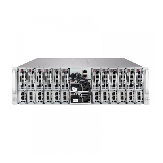
Chapter 1: Introduction Front Features The SC939HC-R2K04BP is a 3U chassis holding 12 discreet computing nodes. The chassis front offers access to the dual power modules. It also includes two dedicated LAN ports to provide IPMI management capabilities for all nodes. Note: The IPMI connections can be used in two ways. -
Page 12: Rear Features
SuperServer 5039MC-H12TRF User's Manual Rear Features The illustration below shows the features included on the rear of the chassis. Power Plugs (2) Exhaust Fans (4) Figure 1-4. Chassis Rear View... -
Page 13: Motherboard Layout
Chapter 1: Introduction 1.5 Motherboard Layout Below is a layout of the X11SCE-F with jumper, connector, and LED locations shown. See the table on the following page for descriptions. For detailed descriptions, pinout information and jumper settings, refer to Chapter 4. JPME1 LED5 JKVM1... -
Page 14: Motherboard Jumpers, Connectors, And Leds
SuperServer 5039MC-H12TRF User's Manual Motherboard Jumpers, Connectors, and LEDs Jumper Description Default Setting JBT1 CMOS Clear Open (Normal) JPG1 VGA Enable Pins 1-2 (Enable) JPME1 ME Recovery Pins 1-2 (Normal) JPME2 Manufacturing Mode Pins 1-2 (Normal) JWD1 Watch Dog Timer... - Page 15 Chapter 1: Introduction PCIe3.0_x8 SVID IMVP8 PCIe x8 MLP SLOT IMVP8 8.0GT/s INTEL LGA1151 SATA-III DDR4 (CHA) DIMMA0 6Gb/s I-SATA[3]/NVMe1 PCIe3.0_x8 2666MHz Socket-H4 PCIe3.0x4 DIMMA1 8.0GT/s 8.0GT/s SATA-III DDR4 (CHB) DIMMB0 6Gb/s I-SATA[4]/NVMe2 2666MHz PCIe3.0x4 DIMMB1 8.0GT/s SATA-III I-SATA[5] x4 DMI 6Gb/s 8GT/s SATA-III...
-
Page 16: Chapter 2 Installation In A Rack
SuperServer 5039MC-H12TRF User's Manual Chapter 2 Installation in a Rack This chapter provides advice and instructions for mounting your system in a rack. 2.1 Preparing for Setup The box in which the system was shipped should include the hardware needed to install it into the rack. -
Page 17: Server Precautions
Chapter 2 Installation in a Rack Server Precautions • Review the electrical and general safety precautions in Chapter 3. • Determine the placement of each component in the rack before you install the rails. • Install the heaviest server components at the bottom of the rack first and then work your way up. -
Page 18: Reliable Ground
SuperServer 5039MC-H12TRF User's Manual Reliable Ground A reliable ground must be maintained at all times. To ensure this, the rack itself should be grounded. Particular attention should be given to power supply connections other than the direct connections to the branch circuit (i.e. the use of power strips, etc.). -
Page 19: Installing The Rails
Chapter 2 Installation in a Rack 2.2 Installing the Rails Use the procedure below for installing the system to a rack. 1. Decide where you want to place the system into the rack (see "Rack Mounting Considerations" in the previous section). 2. -
Page 20: Installing The Server
SuperServer 5039MC-H12TRF User's Manual Figure 2-2. Securing the Rails to the Rack 2.3 Installing the Server 1. If you want to install the optional chassis handles, use screws including a thumbscrew through the bottom hole of each handle. Note: These handles need only be installed when mounting the system into a short rack. - Page 21 Chapter 2 Installation in a Rack Figure 2-3. Installing the System into the Rack Stability hazard. The rack stabilizing mechanism must be in place, or the rack must be bolted to the floor before you slide the unit out for servicing. Failure to stabilize the rack can cause the rack to tip over.
-
Page 22: Chapter 3 Maintenance And Component Installation
SuperServer 5039MC-H12TRF User's Manual Chapter 3 Maintenance and Component Installation This chapter provides instructions on installing and replacing main system components. To prevent compatibility issues, only use components that match the specifications and/or part numbers given. Installation or replacement of most components require that power first be removed from the system. -
Page 23: Accessing The System
Chapter 3: Maintenance and Component Installation 3.2 Accessing the System Top Cover A portion of the chassis top is removable to allow access to the system fans and backplane. Removing the Top Cover 1. Remove power from the system as described in Section 3.1. 2. -
Page 24: Removing And Installing Motherboard Nodes
SuperServer 5039MC-H12TRF User's Manual Removing and Installing Motherboard Nodes The system features twelve removable nodes. Each node contains an individual motherboard and hard drives mounted on a sled, which allows it to easily be installed and removed from the chassis. -
Page 25: Connecting To A Node
Chapter 3: Maintenance and Component Installation Connecting to a Node USB, COM, and serial port capabilties can be added to any node through the KVM port on the front. Plug in the adapter (dongle) to use these ports. Figure 3-3. Adapter to Provide USB, COM, and Serial Ports... -
Page 26: Motherboard Components
• Refer to the Supermicro website for updates on CPU support. Installing the Processor 1. Remove power from the system as described in Section 3.1. - Page 27 Chapter 3: Maintenance and Component Installation 3. Lift open the load plate. Load Plate Open Socket Key Processor Notches Figure 3-5. Placing the Processor into the Socket 4. Use your thumb and your index finger to hold the edges of the processor. Do not touch the socket contacts or the bottom of the processor.
- Page 28 SuperServer 5039MC-H12TRF User's Manual 6. Gently close the load plate onto the processor. The plastic protective cover on the load plate will pop off. Save the cover to protect the socket if the processor is ever removed. 7. Making sure the slot in the load plate slides under the retaining post, close and latch the locking lever.
- Page 29 Chapter 3: Maintenance and Component Installation Installing a Heatsink A passive type heatsink is used on the X11SCE-F motherboard. Note: Do not apply any thermal grease to the heatsink or the CPU; the required amount has already been applied. 1. Place the heatsink on top of the CPU so that the four mounting holes are aligned with those on the heatsink retention mechanism.
-
Page 30: Memory Installation
2666MHz in four slots. Populating the DIMM slots with pairs of memory modules of the same type, speed, and size will result in interleaved memory, which improves performance. Check the Supermicro website for possible updates to memory support. DIMM Module Population Configuration For optimal memory performance, follow the table below when populating memory. -
Page 31: Dimm Module Population Sequence
Chapter 3: Maintenance and Component Installation DIMM Module Population Sequence When installing memory modules, the DIMM slots must be populated in the following order: DIMMB2, DIMMA2, then DIMMB1, DIMMA1. The blue slots must be populated first. Towards the CPU DIMMA1 DIMMA2 (Blue Slot) DIMMB1 DIMMB2 (Blue Slot) -
Page 32: Install Procedure
Caution: Exercise extreme caution when installing or removing memory modules to prevent damage to the DIMMs or slots. Note: Visit the product page on the Supermicro website for possible updates to memory support (www.supermicro.com). Removal Procedure To remove a DIMM module, unlock the release tabs then pull the module from the slot. -
Page 33: Expansion Module
Chapter 3: Maintenance and Component Installation Expansion Module Each of the twelve nodes includes a single MicroLP expansion module providing two LAN connections. Currently, there are four supported for the 5039MC-H12TRF system. • One Micro LP PCI-E 3.0 x8 slot •... -
Page 34: Motherboard Battery
SuperServer 5039MC-H12TRF User's Manual Motherboard Battery The motherboard uses non-volatile memory to retain system information when system power is removed. This memory is powered by a lithium battery residing on the motherboard. Replacing the Battery 1. Remove power from the system as described in section 3.1 and remove the node from the chassis. -
Page 35: Chassis Components
Chapter 3: Maintenance and Component Installation 3.4 Chassis Components Hard Drives The hard drives are installed directly to the node tray. For this reason, hard drives are not hot- swappable as the tray must be removed from the system. Two 3.5", four 2.5", or a combination of one 3.5"... - Page 36 SuperServer 5039MC-H12TRF User's Manual Figure 3-12. Installing Two 3.5" and Four 2.5" Hard Drives Note: Enterprise level hard disk drives are recommended for use in Supermicro chassis and servers. For information on recommended HDDs, visit the Supermicro website at http://www.
-
Page 37: System Cooling
Chapter 3: Maintenance and Component Installation System Cooling Corresponding Nodes and Fans The 5039MC-H12TRF contains twelve individual motherboards contained in separate nodes. Three nodes each share a common fan (see figure below). By default, there is one fan zone for the entire system. This may be changed to two fan zones by opening jumper JP37 on the BPN-SAS-939HS. -
Page 38: Replacing Fans
SuperServer 5039MC-H12TRF User's Manual Replacing Fans Four 9-cm fans circulate air through the chassis to lower the internal temperature. These fans are designed to be easily changed, with no tools required and no need to remove any other parts inside the chassis. -
Page 39: Air Shroud
Chapter 3: Maintenance and Component Installation Air Shroud The air shroud is used to concentrate airflow to maximize fan efficiency. The air shroud does not require screws to set up. Installing the Air Shroud 1. Remove the node from the chassis onto a flat, non-conductive surface. 2. -
Page 40: Power Supply
SuperServer 5039MC-H12TRF User's Manual Power Supply The chassis features redundant power supplies. They are hot-swappable, meaning they can be changed without powering down the system. New units can be ordered directly from Supermicro or authorized distributors. These power supplies are auto-switching capable. This feature enables them to automatically sense the input voltage and operate at a 100-120v or 180-240v. -
Page 41: Chapter 4 Motherboard Connections
Note: UID can also be triggered using IPMI on the motherboard. For more information on IPMI, please refer to the IPMI User's Guide posted on our website at http://www.supermicro.com. 4.2 Headers and Connectors... -
Page 42: Ports
M.2 connector. These SATA ports are supported by the Intel C246 PCH chipset. I-SATA6 can be used with Supermicro SuperDOMs that are yellow SATA DOM connectors with power pins built in, and do not require external power cables. Supermicro SuperDOMs are backward- compatible with regular SATA HDDs or SATA DOMs that need external power cables. -
Page 43: Jumpers
Note: UID can also be triggered via IPMI on the motherboard. For more information on IPMI, please refer to the IPMI User's Guide posted on our website at http://www.supermicro.com/ support/manuals/. UID LED... - Page 44 SuperServer 5039MC-H12TRF User's Manual CMOS Clear JBT1 is used to clear CMOS, which will also clear any passwords. Instead of pins, this jumper consists of contact pads to prevent accidentally clearing the contents of CMOS. To Clear CMOS 1. First power down the system and unplug the power cord(s).
- Page 45 Chapter 4: Motherboard Connections VGA Enable/Disable JPG1 allows you to enable or disable the VGA port using the onboard graphics controller. The default setting is Enabled. VGA Enable/Disable Jumper Settings Jumper Setting Definition Pins 1-2 Enabled Pins 2-3 Disabled Watch Dog JWD1 controls the Watch Dog function.
-
Page 46: Led Indicators
SuperServer 5039MC-H12TRF User's Manual 4.5 LED Indicators BMC Heartbeat LED BMC_HB_LED1 is the BMC heartbeat LED. When the LED is blinking green, BMC is functioning normal. Refer to the table below for more information. BMC Heartbeat LED Indicator LED Color... -
Page 47: Chapter 5 Software
USB/SATA DVD drive, or a USB flash drive, or the IPMI KVM console. 2. Retrieve the proper RST/RSTe driver. Go to the Supermicro web page for your motherboard and click on "Download the Latest Drivers and Utilities", select the proper driver, and copy it to a USB flash drive. - Page 48 SuperServer 5039MC-H12TRF User's Manual 4. During Windows Setup, continue to the dialog where you select the drives on which to install Windows. If the disk you want to use is not listed, click on “Load driver” link at the bottom left corner.
-
Page 49: Driver Installation
The Supermicro website contains drivers and utilities for your system at https://www. supermicro.com/wftp/driver. Some of these must be installed, such as the chipset driver. After accessing the website, go into the CDR_Images (in the parent directory of the above link) and locate the ISO file for your motherboard. Download this file to to a USB flash drive or a DVD. -
Page 50: Superdoctor ® 5
5.3 SuperDoctor ® The Supermicro SuperDoctor 5 is a program that functions in a command-line or web-based interface for Windows and Linux operating systems. The program monitors such system health information as CPU temperature, system voltages, system power consumption, fan speed, and provides alerts via email or Simple Network Management Protocol (SNMP). -
Page 51: Ipmi
IP address of the other nodes. In IPMI CLI view, typing the command "SMCIPMITool -tp info", allows the MCU information of all 12 nodes to be displayed. For general documentation and information on IPMI, please visit our website at: http://www.supermicro.com/products/nfo/IPMI.cfm. -
Page 52: Chapter 6 Uefi Bios
SuperServer 5039MC-H12TRF User's Manual Chapter 6 UEFI BIOS 6.1 Introduction This chapter describes the AMIBIOS Setup utility for the X11SCE-F motherboard. The BIOS is stored in a flash chip and can be easily upgraded using a flash program. Note: Due to periodic changes to the BIOS, some settings may have been added or deleted and might not yet be recorded in this manual. -
Page 53: Main Menu
The time is entered in HH:MM:SS format. Please note that time is in a 24-hour format. For example, 5:30 A.M. appears as 05:30:00 and 5:30 P.M. as 17:30:00. Supermicro X11SCE-F BIOS Version This item displays the version of the BIOS ROM used in the system. -
Page 54: Advanced Setup Configurations
SuperServer 5039MC-H12TRF User's Manual Memory Information Total Memory This item displays the total size of memory available in the system. Memory Speed This item displays the memory speed. 6.3 Advanced Setup Configurations Caution: Take caution when changing the Advanced settings. An incorrect value, a very high DRAM frequency, or an incorrect DRAM timing setting may make the system unstable. - Page 55 Chapter 6: UEFI BIOS AddOn ROM Display Mode Use this feature to set the display mode for the Option ROM. Select Keep Current to display the current AddOn ROM setting. Select Force BIOS to use the Option ROM display set by the system BIOS.
- Page 56 SuperServer 5039MC-H12TRF User's Manual Restore on AC Power Loss Use this feature to set the power state after a power outage. Select Stay-Off for the system power to remain off after a power loss. Select Power-On for the system power to be turned on after a power loss. Select Last State to allow the system to resume its last power state before a power loss.
- Page 57 Chapter 6: UEFI BIOS Hyper-threading (Available when supported by the CPU) Select Enabled to support Intel Hyper-threading Technology to enhance CPU performance. The options are Enabled and Disabled. Active Processor Cores This feature determines how many CPU cores will be activated for each CPU. When all is selected, all cores in the CPU will be activated.
- Page 58 SuperServer 5039MC-H12TRF User's Manual Turbo Mode Select Enabled for processor cores to run faster than the frequency specified by the manufacturer. The options are Disabled and Enabled. Package Power Limit MSR Lock Select Enabled to lock the package power limit for the model specific registers. The options are Disabled and Enabled.
- Page 59 Chapter 6: UEFI BIOS C-State Auto Demotion Use this feature to prevent unnecessary excursions into the C-states to improve latency. The options are Disabled, C1, C3, and C1 and C3. C-State Un-Demotion This feature allows the user to enable or disable the un-demotion of C-State. The options are Disabled, C1, C3, and C1 and C3.
- Page 60 SuperServer 5039MC-H12TRF User's Manual • SA PCIe Code Version • VT-d VT-d Select Enabled to enable Intel Virtualization Technology support for Direct I/O VT-d by reporting the I/O device assignments to VMM through the DMAR ACPI Tables. This feature offers fully-protected I/O resource-sharing across the Intel platforms, providing the user with greater reliability, security and availability in networking and data-sharing.
- Page 61 Chapter 6: UEFI BIOS DVMT Pre-Allocated Dynamic Video Memory Technology (DVMT) allows dynamic allocation of system memory to be used for video devices to ensure best use of available system memory based on the DVMT 5.0 platform. The options are 32M, 64M, 96M, 128M, 160M, 192M, 224M, 256M, 288M, 320M, 352M, 384M, 416M, 448M, 480M, 512M, 1024M, 1536M, 2048M, 4M, 8M, 12M, 20M, 24M, 28M, 32M/F7, 36M, 40M, 44M, 48M, 52M, 56M, and 60M.
- Page 62 SuperServer 5039MC-H12TRF User's Manual DMI De-Emphasis Control Use this feature to configure the De-emphasis control on DMI. The options are -6dB and -3.5dB. PEG Port Configuration PEG 0:1:0 PEG0 Enable Root Port Use this feature to enable or disable the PCI Express Graphics (PEG) device in the port specified by the user.
- Page 63 Chapter 6: UEFI BIOS • DIMMA1 • DIMMA2 • DIMMB1 • DIMMB2 • Memory Timings (tCL-tRCD-tRP-tRAS) Maximum Memory Frequency Use this feature to set the maximum memory frequency for onboard memory modules. The options are Auto, 1067, 1200, 1333, 1400, 1600, 1800, 1867, 2000, 2133, 2200, and 2400. Max TOLUD This feature sets the maximum TOLUD value, which specifies the "Top of Low Usable DRAM"...
- Page 64 SuperServer 5039MC-H12TRF User's Manual • Intel PCH SKU Name • Intel PCH Rev ID Port 61h bit-4 Emulation Select Enabled to enable the emulation of Port 61h bit-4 toggling in SMM (System Management Mode). The options are Disabled and Enabled.
- Page 65 Chapter 6: UEFI BIOS Port 0 ~ Port 5 Spin Up Device On an edge detect from 0 to 1, set this item to allow the PCH to initialize the device. The options are Enabled and Disabled. Port 0 ~ Port 5 SATA Device Type Use this item to specify if the SATA port specified by the user should be connected to a Solid State drive or a Hard Disk Drive.
- Page 66 SuperServer 5039MC-H12TRF User's Manual PXE boot wait time Use this option to specify the wait time to press the ESC key to abort the PXE boot. Press "+" or "-" on your keyboard to change the value. The default setting is 0.
- Page 67 Chapter 6: UEFI BIOS Serial Port 2 (SOL) Change Settings This feature specifies the base I/O port address and the Interrupt Request address of a serial port specified by the user. Select Auto to allow the BIOS to automatically assign the base I/O and IRQ address.
- Page 68 SuperServer 5039MC-H12TRF User's Manual COM1 Console Redirection Settings This feature allows the user to specify how the host computer will exchange data with the client computer, which is the remote computer used by the user. COM1 Terminal Type This feature allows the user to select the target terminal emulation type for Console Redirection.
- Page 69 Chapter 6: UEFI BIOS COM1 Recorder Mode Select Enabled to capture the data displayed on a terminal and send it as text messages to a remote server. The options are Disabled and Enabled. COM1 Resolution 100x31 Select Enabled for extended-terminal resolution support. The options are Disabled and Enabled.
- Page 70 SuperServer 5039MC-H12TRF User's Manual transmission speed may be required for long and busy lines. The options are 9600, 19200, 38400, 57600 and 115200 (bits per second). SOL Data Bits Use this feature to set the data transmission size for Console Redirection. The options are 7 Bits and 8 Bits.
- Page 71 Chapter 6: UEFI BIOS SOL Redirection After BIOS POST Use this feature to enable or disable legacy Console Redirection after BIOS POST. When set to Bootloader, legacy Console Redirection is disabled before booting the OS. When set to Always Enable, legacy Console Redirection remains enabled when booting the OS. The options are Always Enable and Bootloader.
- Page 72 SuperServer 5039MC-H12TRF User's Manual ACPI Settings High Precision Event Timer Select Enabled to activate the High Performance Event Timer (HPET) that produces periodic interrupts at a much higher frequency than a Real-time Clock (RTC) does in synchronizing multimedia streams, providing smooth playback and reducing the dependency on other timestamp calculation devices, such as an x86 RDTSC Instruction embedded in the CPU.
- Page 73 Chapter 6: UEFI BIOS Pending TPM operation Use this item to schedule a TPM-related operation to be performed by a security device for system data integrity. Your system will reboot to carry out a pending TPM operation. The options are None and TPM Clear. Platform Hierarchy Use this item to disable or enable platform hierarchy for platform protection.
-
Page 74: Event Logs
SuperServer 5039MC-H12TRF User's Manual Add an Attempt Delete Attempts Change Attempt order 6.4 Event Logs Use this feature to configure Event Log settings. Change SMBIOS Event Log Settings Enabling/Disabling Options SMBIOS Event Log Change this item to enable or disable all features of the SMBIOS Event Logging during system boot. - Page 75 Chapter 6: UEFI BIOS When Log is Full Select Erase Immediately for all messages to be automatically erased from the event log when the event log memory is full. The options are Do Nothing and Erase Immediately. SMBIOS Event Long Standard Settings Log System Boot Event This option toggles the System Boot Event logging to enabled or disabled.
-
Page 76: Ipmi
SuperServer 5039MC-H12TRF User's Manual 6.5 IPMI Use this feature to configure Intelligent Platform Management Interface (IPMI) settings. BMC Firmware Revision This item indicates the IPMI firmware revision used in your system. IPMI Status (Baseboard Management Controller) This item indicates the status of the IPMI firmware installed in your system. - Page 77 Chapter 6: UEFI BIOS When SEL is Full This feature allows the user to decide what the BIOS should do when the system event log is full. Select Erase Immediately to erase all events in the log when the system event log is full.
-
Page 78: Security
SuperServer 5039MC-H12TRF User's Manual Gateway IP Address This item displays the Gateway IP address for this computer. This should be in decimal and in dotted quad form (i.e., 172.31.0.1). VLAN Use this item to enable or disable the IPMI VLAN function. The options are Disable and Enable. - Page 79 Chapter 6: UEFI BIOS Secure Boot Menu This section displays the contents of the following secure boot features: • System Mode • Secure Boot • Vendor Keys Secure Boot Use this item to enable secure boot. The options are Disabled and Enabled. Secure Boot Mode Use this item to select the secure boot mode.
- Page 80 SuperServer 5039MC-H12TRF User's Manual Key Exchange Key Set New Key Select Yes to load the KEK from the manufacturer's defaults. Select No to load the KEK from a file. The options are Yes and No. Append Key Select Yes to add the KEK from the manufacturer's defaults list to the existing KEK. Select No to load the KEK from a file.
-
Page 81: Boot
Chapter 6: UEFI BIOS 6.7 Boot Use this feature to configure Boot Settings. Boot Mode Select Use this item to select the type of device that the system is going to boot from. The options are Legacy, UEFI, and Dual. The default setting is Dual. Fixed Boot Order Priorities This option prioritizes the order of bootable devices that the system to boot from. - Page 82 SuperServer 5039MC-H12TRF User's Manual • Legacy/UEFI/Dual/Boot Option #9 • Legacy/UEFI/Dual/Boot Option #10 • Legacy/UEFI/Dual/Boot Option #11 • Legacy/UEFI/Dual/Boot Option #12 • Legacy/UEFI/Dual/Boot Option #13 • Legacy/UEFI/Dual/Boot Option #14 • Legacy/UEFI/Dual/Boot Option #15 Delete Boot Option Use this feature to remove a pre-defined boot device from which the system will boot during startup.
-
Page 83: Save & Exit
Chapter 6: UEFI BIOS 6.8 Save & Exit Select the Exit tab from the BIOS setup utility screen to enter the Exit BIOS Setup screen. Discard Changes and Exit Select this option to quit the BIOS Setup without making any permanent changes to the system configuration, and reboot the computer. - Page 84 SuperServer 5039MC-H12TRF User's Manual Default Options Restore Optimized Defaults To set this feature, select Restore Optimized Defaults from the Save & Exit menu and press <Enter>. These are factory settings designed for maximum system stability, but not for maximum performance.
- Page 85 Supermicro's Technical Support department for assistance. Only certified technicians should attempt to install or configure components. Read this appendix in its entirety before installing or configuring components in the Supermicro chassis. These warnings may also be found on our website at http://www.supermicro.com/about/...
- Page 86 Appendix A: Standardized Warning Statements Warnung WICHTIGE SICHERHEITSHINWEISE Dieses Warnsymbol bedeutet Gefahr. Sie befinden sich in einer Situation, die zu Verletzungen führen kann. Machen Sie sich vor der Arbeit mit Geräten mit den Gefahren elektrischer Schaltungen und den üblichen Verfahren zur Vorbeugung vor Unfällen vertraut. Suchen Sie mit der am Ende jeder Warnung angegebenen Anweisungsnummer nach der jeweiligen Übersetzung in den übersetzten Sicherheitshinweisen, die zusammen mit diesem Gerät ausgeliefert wurden.
- Page 87 SuperServer 5039MC-H12TRF User's Manual . ٌ ا ك ً ف حالة و ٌ يك أى تتسبب ف اصابة جسذ ة ٌ هذا الزهز ع ٌ خطز !تحذ ز قبل أى تعول عىل أي هعذات،يك عىل علن بالوخاطز ال ا ٌجوة عي الذوائز...
- Page 88 Appendix A: Standardized Warning Statements Warnung Vor dem Anschließen des Systems an die Stromquelle die Installationsanweisungen lesen. ¡Advertencia! Lea las instrucciones de instalación antes de conectar el sistema a la red de alimentación. Attention Avant de brancher le système sur la source d'alimentation, consulter les directives d'installation. .יש...
- Page 89 SuperServer 5039MC-H12TRF User's Manual Warnung Dieses Produkt ist darauf angewiesen, dass im Gebäude ein Kurzschluss- bzw. Überstromschutz installiert ist. Stellen Sie sicher, dass der Nennwert der Schutzvorrichtung nicht mehr als: 250 V, 20 A beträgt. ¡Advertencia! Este equipo utiliza el sistema de protección contra cortocircuitos (o sobrecorrientes) del edificio.
- Page 90 Appendix A: Standardized Warning Statements Power Disconnection Warning Warning! The system must be disconnected from all sources of power and the power cord removed from the power supply module(s) before accessing the chassis interior to install or remove system components. 電源切断の警告...
- Page 91 SuperServer 5039MC-H12TRF User's Manual يجب فصم اننظاو من جميع مصادر انطاقت وإ ز انت سهك انكهرباء من وحدة امداد انطاقت قبم انىصىل إىن امنناطق انداخهيت نههيكم نتثبيج أو إ ز انت مكىناث الجهاز 경고! 시스템에 부품들을 장착하거나 제거하기 위해서는 섀시 내부에 접근하기 전에 반드시 전원...
- Page 92 Appendix A: Standardized Warning Statements Attention Il est vivement recommandé de confier l'installation, le remplacement et la maintenance de ces équipements à des personnels qualifiés et expérimentés. !אזהרה .צוות מוסמך בלבד רשאי להתקין, להחליף את הציוד או לתת שירות עבור הציוד واملدربيه...
- Page 93 SuperServer 5039MC-H12TRF User's Manual Warnung Diese Einheit ist zur Installation in Bereichen mit beschränktem Zutritt vorgesehen. Der Zutritt zu derartigen Bereichen ist nur mit einem Spezialwerkzeug, Schloss und Schlüssel oder einer sonstigen Sicherheitsvorkehrung möglich. ¡Advertencia! Esta unidad ha sido diseñada para instalación en áreas de acceso restringido. Sólo puede obtenerse acceso a una de estas áreas mediante la utilización de una herramienta especial,...
- Page 94 Appendix A: Standardized Warning Statements Battery Handling Warning! There is the danger of explosion if the battery is replaced incorrectly. Replace the battery only with the same or equivalent type recommended by the manufacturer. Dispose of used batteries according to the manufacturer's instructions 電池の取り扱い...
- Page 95 SuperServer 5039MC-H12TRF User's Manual هناك خطر من انفجار يف حالة اسحبذال البطارية بطريقة غري صحيحة فعليل اسحبذال البطارية فقط بنفس النىع أو ما يعادلها مام أوصث به الرشمة املصنعة جخلص من البطاريات املسحعملة وفقا لحعليامت الرشمة الصانعة 경고! 배터리가 올바르게 교체되지 않으면 폭발의 위험이 있습니다. 기존 배터리와 동일하거나 제...
- Page 96 Appendix A: Standardized Warning Statements ¡Advertencia! Puede que esta unidad tenga más de una conexión para fuentes de alimentación. Para cortar por completo el suministro de energía, deben desconectarse todas las conexiones. Attention Cette unité peut avoir plus d'une connexion d'alimentation. Pour supprimer toute tension et tout courant électrique de l'unité, toutes les connexions d'alimentation doivent être débranchées.
- Page 97 SuperServer 5039MC-H12TRF User's Manual Backplane Voltage Warning! Hazardous voltage or energy is present on the backplane when the system is operating. Use caution when servicing. バックプレーンの電圧 システムの稼働中は危険な電圧または電力が、 バックプレーン上にかかっています。 修理する際には注意く ださい。 警告 当系统正在进行时,背板上有很危险的电压或能量,进行维修时务必小心。 警告 當系統正在進行時,背板上有危險的電壓或能量,進行維修時務必小心。 Warnung Wenn das System in Betrieb ist, treten auf der Rückwandplatine gefährliche Spannungen oder Energien auf.
- Page 98 Appendix A: Standardized Warning Statements هناك خطز مه التيار الكهزبايئ أوالطاقة املىجىدة عىل اللىحة عندما يكىن النظام يعمل كه حذ ر ا عند خدمة هذا الجهاس 경고! 시스템이 동작 중일 때 후면판 (Backplane)에는 위험한 전압이나 에너지가 발생 합니다. 서비스 작업 시 주의하십시오. Waarschuwing Een gevaarlijke spanning of energie is aanwezig op de backplane wanneer het systeem in gebruik is.
- Page 99 SuperServer 5039MC-H12TRF User's Manual תיאום חוקי החשמל הארצי !אזהרה .התקנת הציוד חייבת להיות תואמת לחוקי החשמל המקומיים והארציים تركيب املعدات الكهربائية يجب أن ميتثل للقىاويه املحلية والىطىية املتعلقة بالكهرباء 경고! 현 지역 및 국가의 전기 규정에 따라 장비를 설치해야 합니다.
- Page 100 Appendix A: Standardized Warning Statements Attention La mise au rebut ou le recyclage de ce produit sont généralement soumis à des lois et/ou directives de respect de l'environnement. Renseignez-vous auprès de l'organisme compétent. סילוק המוצר !אזהרה .סילוק סופי של מוצר זה חייב להיות בהתאם להנחיות וחוקי המדינה التخلص...
- Page 101 SuperServer 5039MC-H12TRF User's Manual Warnung Gefährlich Bewegende Teile. Von den bewegenden Lüfterblätter fern halten. Die Lüfter drehen sich u. U. noch, wenn die Lüfterbaugruppe aus dem Chassis genommen wird. Halten Sie Finger, Schraubendreher und andere Gegenstände von den Öffnungen des Lüftergehäuses entfernt.
- Page 102 Verbindungskabeln, Stromkabeln und/oder Adapater, die Ihre örtlichen Sicherheitsstandards einhalten. Der Gebrauch von anderen Kabeln und Adapter können Fehlfunktionen oder Feuer verursachen. Die Richtlinien untersagen das Nutzen von UL oder CAS zertifizierten Kabeln (mit UL/CSA gekennzeichnet), an Geräten oder Produkten die nicht mit Supermicro gekennzeichnet sind.
- Page 103 حجم املوصل والقابس السليم. استخدام أي كابالت ومحوالت أخرى قد يتسبب يف عطل أو حريق. يحظر قانون السالمة لألجهزة الكهربائية واملعدات استخدام الكابالت املعتمدة من قبلUL أوCSA ( والتي تحمل عالمةUL/CSA) مع أي معدات أخرى غري املنتجات املعنية واملحددة من قبلSupermicro.
- Page 104 사항을 준수하여 제공되거나 지정된 연결 혹은 구매 케이블, 전원 케이블 및 AC 어댑터를 사용하십시오. 다른 케이블이나 어댑터를 사용하면 오작동이나 화재가 발생할 수 있습니다. 전기 용품 안전법은 UL 또는 CSA 인증 케이블 (코드에 UL / CSA가 표시된 케이블)을 Supermicro 가 지정한 제품 이외의 전기 장치에 사용하는 것을 금지합니다. Stroomkabel en AC-Adapter...
- Page 105 Warning: Do not upgrade the BIOS unless your system has a BIOS-related issue. Flashing the wrong BIOS can cause irreparable damage to the system. In no event shall Supermicro be liable for direct, indirect, special, incidental, or consequential damages arising from a BIOS update.
- Page 106 SuperServer 5039MC-H12TRF User's Manual The file system supported by UEFI is FAT (including FAT12, FAT16, and FAT32) installed on a bootable or non-bootable USB-attached device. However, the BIOS might need several minutes to locate the SUPER.ROM file if the media size becomes too large because it contains too many folders and files.
- Page 107 Appendix B: UEFI BIOS Recovery 4. After locating the new BIOS binary image, the system will enter the BIOS Recovery menu as shown below. Note: At this point, you may decide if you want to start with BIOS recovery. If you decide to proceed with BIOS recovery, follow the procedures below.
- Page 108 SuperServer 5039MC-H12TRF User's Manual 6. After the process of BIOS recovery is completed, press any key to reboot the system. 7. Using a different system, extract the BIOS package into a bootable USB flash drive. 8. When a DOS prompt appears, enter FLASH.BAT BIOSname.### at the prompt.
- Page 109 Appendix C: System Specifications Appendix C System Specifications Processors Single Intel Xeon E-2100 in an H4 LGA1151 type socket, 95W max TDP. Note: The system does not support the redundant power feature under special circumstances when the CPUs are under Turbo mode or all CPUs consume 95W or more under stress simultaneously.
- Page 110 SuperServer 5039MC-H12TRF User's Manual Power Supply Model: PWS-2K04F-1R, 80+ level Titanium Total Output Power: 1000W/1800W/1980W/2000W AC Input Voltages: 100-127 V, 200-220 V, 220-230 V, 230-240 V, 200-240V Rated Input Frequency: 50-60 Hz Rated Output Power: Max.: 83.3A & Min..: 0A (100Vac-127Vac) Max.: 150A &...
Need help?
Do you have a question about the SUPERSERVER 5039MC-H12TRF and is the answer not in the manual?
Questions and answers