Table of Contents
Advertisement
Quick Links
Advertisement
Table of Contents

Subscribe to Our Youtube Channel
Related Manuals for Supermicro SuperServer 5039C-I


Summary of Contents for Supermicro SuperServer 5039C-I
- Page 1 SuperServer ® 5039C-I USER’S MANUAL Revision 1.0...
- Page 2 State of California, USA. The State of California, County of Santa Clara shall be the exclusive venue for the resolution of any such disputes. Supermicro's total liability for all claims will not exceed the price paid for the hardware product.
- Page 3 About this Manual This manual is written for professional system integrators and PC technicians. It provides information for the installation and use of the SuperServer 5039C-I. Installation and maintenance should be performed by experienced technicians only. Please refer to the 5039C-I specifications page on our website for updates on supported memory, processors and operating systems (http://www.supermicro.com).
-
Page 4: Table Of Contents
Preface Table of Contents Chapter 1 Introduction 1.1 Overview ..........................8 1.2 Unpacking the System ......................8 1.3 System Specifications ......................9 1.4 System Chassis Features ....................10 Control Panel ........................10 Front Features ........................11 Rear Features ...........................12 1.5 Motherboard Layout ......................13 Quick Reference Table ......................14 Chapter 2 Server Installation 2.1 Overview ..........................17 2.2 Preparing for Setup ......................17... - Page 5 SuperServer 5039C-I User's Manual 3.5 Chassis Components ......................29 Hard Drives ........................29 Optional Drive Bays ......................31 System Cooling .........................32 Replacing the System Fan ....................32 Power Supply ........................33 Chapter 4 Motherboard Connections 4.1 Power Connections ......................34 4.2 Headers and Connectors ....................35 Front Control Panel ......................39 4.4 Rear I/O Ports ........................42...
- Page 6 Appendix A BIOS Error Codes A.1 BIOS Error POST (Beep) Codes ..................93 Appendix B Standardized Warning Statements for AC Systems Appendix C System Specifications Appendix D UEFI BIOS Recovery Appendix E BSMI RoHS...
- Page 7 Super Micro Computer, Inc. 980 Rock Ave. San Jose, CA 95131 U.S.A. Tel: +1 (408) 503-8000 Fax: +1 (408) 503-8008 Email: marketing@supermicro.com (General Information) support@supermicro.com (Technical Support) Website: www.supermicro.com Europe Address: Super Micro Computer B.V. Het Sterrenbeeld 28, 5215 ML...
-
Page 8: Chapter 1 Introduction
Black LITE-ON 5.25" 24X DVD-RW SATA Drive (Optional) DVM-LITE-DVDRW24-HBT 1.2 Unpacking the System Inspect the box the SuperServer 5039C-I was shipped in and note if it was damaged in any way. If any equipment appears damaged, please file a damage claim with the carrier who delivered it. -
Page 9: System Specifications
Four (4) DIMM slots to support up to 64 GB of unbuffered ECC DDR4 ECC 2666 Mhz speed SDRAM up to 16 GB size at 1.2V Note: For the latest CPU/memory updates, please refer to our website at http://www.supermicro.com/products/ motherboard. Chipset... -
Page 10: System Chassis Features
SuperServer 5039C-I User's Manual 1.4 System Chassis Features Control Panel The switches and LEDs located on the control panel are described below. See Chapter 4 for more details on the control panel. Figure 1-1. Control Panel View Control Panel Features... -
Page 11: Front Features
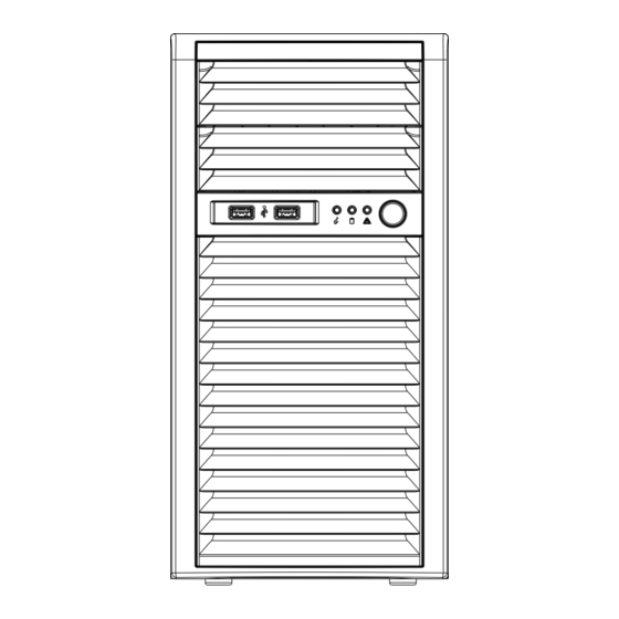
Chapter 1: Introduction Front Features The SC731i-403B is a mini-tower chassis. See the illustration below for the features included on the front of the chassis. Figure 1-2. Chassis Front View Front Chassis Features Item Feature Description Supports two fixed 5.25" drives (such as an optional DVD-ROM or Blu- Fixed Drive Area ray drive) Control Panel... -
Page 12: Rear Features
SuperServer 5039C-I User's Manual Rear Features The illustration below shows the features included on the rear of the chassis. Figure 1-3. Chassis Rear View Rear Chassis Features Item Feature Description PS2/ATX 400W multi-output power supply 80Plus Gold (P/N: PWS- Power Supply... -
Page 13: Motherboard Layout
Chapter 1: Introduction 1.5 Motherboard Layout Below is a layout of the X11SCL-F with jumper, connector and LED locations shown. See the table on the following page for descriptions. For detailed descriptions, pinout information and jumper settings, refer to Chapter 4. USB6/7 (3.0) COM1 LEDBMC... -
Page 14: Quick Reference Table
SuperServer 5039C-I User's Manual Note: Use only the correct type of onboard CMOS battery as specified by the manufacturer. Do not install the onboard battery upside down to avoid possible explosion. See chapter 3 for details. Quick Reference Table Jumper... - Page 15 Chapter 1: Introduction Connector Description MH10, MH11 M.2 Mounting Holes SLOT4, SLOT5 CPU PCI-E 3.0 x4 (in x8) Slots SLOT6 CPU PCI-E 3.0 x8 (in x16) Slot Onboard Buzzer USB0/1 Back Panel Universal Serial Bus (USB) 2.0 Ports USB2/3, USB4/5 Front Accessible USB 2.0 Headers USB6/7 Back Panel USB 3.1 Gen 1 Ports...
- Page 16 SuperServer 5039C-I User's Manual IMVP 8 4 PHASE for Vcore #B-1 #B-0 #A-1 PCI-E X8 Gen3 #A-0 SLOT6 PCIe3.0 x8 (x16) #0-7 Skt-H4 PCI-E X4 Gen3 LGA1151 SLOT5 PCIe3.0 x4 (x8) #8-11 #12-15 DMI3 PCI-E X4 Gen3 SLOT4 PCIe3.0 x4 (x8)
-
Page 17: Chapter 2 Server Installation
SuperServer 5039C-I User's Manual Chapter 2 Server Installation 2.1 Overview This chapter provides advice and instructions for mounting your system in a server rack. If your system is not already fully integrated with processors, system memory, etc., refer to Chapter 4 for details on installing those components. -
Page 18: Chapter 3 Maintenance And Component Installation
SuperServer 5039C-I User's Manual Chapter 3 Maintenance and Component Installation This chapter provides instructions on installing and replacing main system components. To prevent compatibility issues, only use components that match the specifications and/or part numbers given. Installation or replacement of most components require that power first be removed from the system. - Page 19 Chapter 3: Maintenance and Component Installation Cover Handle (B) Slide Tab A Toward Handle Release Tab Figure 3-1. Accessing the System...
-
Page 20: Motherboard Components
CPU socket and none of the socket pins are bent. If they are, contact your retailer. • Refer to the Supermicro website for updates on CPU support. Installing the LGA 1151 Processor 1. Press the load lever down to release the load plate from its locking position. - Page 21 Chapter 3: Maintenance and Component Installation 2. Gently lift the load lever to open the load plate. Remove the plastic protective cover. Do not touch the CPU socket contacts. 3. Locate the triangle on the CPU and CPU socket, which indicates the location of Pin 1. Holding the CPU by the edges with your thumb and index finger, align the triangle on the CPU with the triangle on the socket.
- Page 22 SuperServer 5039C-I User's Manual 5. Close the load plate, then gently push down the load lever into its locking position. CPU properly installed Load lever locked into place Note: You can only install the CPU in one direction. Make sure it is properly inserted into the socket before closing the load plate.
-
Page 23: Installing The Cpu Heatsink
Chapter 3: Maintenance and Component Installation Installing the CPU Heatsink Do not apply thermal grease to the heatsink or the CPU--the required amount has already been applied. 1. Remove the power cord from the system. 2. Place the heatsink on top of the CPU so that the four mounting screws on the heatsink are aligned with holes on the socket. -
Page 24: Removing The Heatsink
SuperServer 5039C-I User's Manual Removing the Heatsink Note: We do not recommend that the CPU or the heatsink be removed. However, if you must remove the heatsink, follow the instructions below to avoid damage. 1. Remove power from the system as described in Section 3.1. -
Page 25: Memory Support And Installation
Chapter 3: Maintenance and Component Installation 3.4 Memory Support and Installation Note: Check the Supermicro website for recommended memory modules. Exercise extreme care when installing or removing DIMM modules to prevent any damage. Memory Support The X11SCL-F supports up to 64GB of unbuffered (UDIMM) DDR4 (288-pin) ECC memory (2-DIMM per channel) with speeds of up to 2666MHz in four memory slots. -
Page 26: General Guidelines For Optimizing Memory Performance
SuperServer 5039C-I User's Manual General Guidelines for Optimizing Memory Performance • The blue slots must be populated first. • Always use DDR4 memory of the same type, size, and speed. • Mixed DIMM speeds can be installed. However, all DIMMs will run at the speed of the slowest DIMM. -
Page 27: Dimm Installation
Chapter 3: Maintenance and Component Installation DIMM Installation COM1 1. Insert the desired number of DIMMs ASpeed AST2500 LAN2 LAN1 IPMI_LAN USB0/1 into the memory slots based on the LEDBMC Intel i210 X11SCL-F recommended DIMM population table on REV:1.01 DESIGNED IN USA page 29. -
Page 28: Pci Expansion Card Installation
SuperServer 5039C-I User's Manual PCI Expansion Card Installation The system has slots for standard size PCI-E cards, allowing them to fit inside the chassis. Installing PCI Expansion Cards Begin by removing power from the system as described in section 3.1. -
Page 29: Chassis Components
8. If desired, each hard drive may be further secured to the drive cage with an additional (optional) screw at the middle of the drive.) Note: Enterprise level hard disk drives are recommended for use in Supermicro chassis and servers. For information on recommended HDDs, visit the Supermicro website at http://www. - Page 30 SuperServer 5039C-I User's Manual Release Tab (A) HDD Cage (B) Figure 3-4. Rotating the Hard Drive Cage Release Tabs Figure 3-5. Installing Drives in the Chassis...
-
Page 31: Optional Drive Bays
Chapter 3: Maintenance and Component Installation Optional Drive Bays The SC731i-403B chassis has two empty 5.25" drive bays that support optional devices such as a DVD-ROM. Installing an Optional Device Begin by removing power from the system as described in section 3.1. 1. -
Page 32: System Cooling
SuperServer 5039C-I User's Manual System Cooling The SC731i-403B includes a super quiet rear system fan that provides cooling for the chassis. No tools or screws are required to install the system fan. Under normal operation, the chassis fan and the power supply fan both run continuously. -
Page 33: Power Supply
Chapter 3: Maintenance and Component Installation Power Supply The 5039C-I chassis includes a 400-watt power supply. The power supply has the capability to automatically sense and operate with an input voltage of 100-240V AC. If it becomes necessary to replace the power supply, follow the instructions below. Replacing the Power Supply Begin by removing power from the system as described in section 3.1 and access the inside of the system as described in section 3.2. -
Page 34: Chapter 4 Motherboard Connections
SuperServer 5039C-I User's Manual Chapter 4 Motherboard Connections This section describes the connections on the motherboard and provides pinout definitions. Note that depending on how the system is configured, not all connections are required. The LEDs on the motherboard are also described here. A severboard layout indicating component locations may be found in Chapter 1. -
Page 35: Headers And Connectors
Port 80 connection. Use this header to enhance system performance and data security. Refer to the table below for pin definitions. Please go to the following link for more information on the TPM: http://www.supermicro.com/manuals/other/TPM.pdf. Trusted Platform Module Header Pin Definitions... - Page 36 SuperServer 5039C-I User's Manual M.2 Slot The X11SCL-F motherboard has one M.2 slot. M.2 was formerly known as Next Generation Form Factor (NGFF) and serves to replace mini PCI-E. M.2 allows for a variety of card sizes, increased functionality, and spatial efficiency. The M.2 socket on the motherboard supports SSD cards in a 2280 / 22110 form factor.
- Page 37 Chapter 4: Motherboard Connections SGPIO Headers There are two Serial Link General Purpose Input/Output (I-SGPIO1, I-SGPIO2) headers located on the motherboard. The SGPIO headers are used to communicate with the enclosure management chip on the back panel. I-SGPIO 1/2 I-SGPIO1 I-SATA 3.0 Ports 0-3 I-SGPIO2 I-SATA 3.0 Ports 4-5...
- Page 38 These SATA ports support RAID 0, 1, 5, and 10. SATA ports provide serial-link signal connections, which are faster than the connections of Parallel ATA. Note: Supermicro SuperDOMs are yellow SATADOM connectors with power pins built in and do not require separate external power cables. These connectors are backwards compatible with non-Supermicro SATADOMS that require an external power supply.
-
Page 39: Front Control Panel
JF1 contains header pins for various buttons and indicators that are normally located on a control panel at the front of the chassis. These connectors are designed specifically for use with Supermicro chassis. See the figure below for the descriptions of the front control panel buttons and LED indicators. - Page 40 SuperServer 5039C-I User's Manual Power Button The Power Button connection is located on pins 1 and 2 of JF1. Momentarily contacting both pins will power on/off the system. This button can also be configured to function as a suspend button (with a setting in the BIOS - see Chapter 4). To turn off the power when the system is in suspend mode, press the button for four seconds or longer.
- Page 41 Chapter 4: Motherboard Connections NIC1/NIC2 (LAN1/LAN2) The Network Interface Controller (NIC) LED connection for LAN port 1 is located on pins 11 and 12 of JF1, and LAN port 2 is on pins 9 and 10. Attach the NIC LED cables here to display network activity.
-
Page 42: Rear I/O Ports
SuperServer 5039C-I User's Manual 4.4 Rear I/O Ports See the layout below for the locations and descriptions of the various I/O ports on the rear of the motherboard. COM1 ASpeed AST2500 LAN2 LAN1 IPMI_LAN USB0/1 LEDBMC Intel i210 X11SCL-F REV:1.01... - Page 43 LED indicator. Note: UID can also be triggered via IPMI on the motherboard. For more information on IPMI, please refer to the IPMI User's Guide posted on our website: https://www.supermicro.com/ support/manuals/ UID Switch...
- Page 44 SuperServer 5039C-I User's Manual Universal Serial Bus (USB) Ports There are two USB 2.0 ports (USB0/1) and two USB 3.1 Gen 1 ports (USB6/7) located on the back I/O panel. The motherboard also has two front access USB 2.0 headers (USB2/3, USB4/5) and one front access USB 3.1 Gen 1 header (USB8/9).
-
Page 45: Jumpers
Chapter 4: Motherboard Connections 4.5 Jumpers Explanation of Jumpers To modify the operation of the motherboard, jumpers are used to choose between optional settings. Jumpers create shorts between two pins to change the function associated with it. Pin 1 is identified with a square solder pad on the printed circuit board. See the motherboard layout page for jumper locations. - Page 46 SuperServer 5039C-I User's Manual ME Manufacturing Mode Close pins 2-3 of jumper JPME2 to bypass SPI flash security and force the system to operate in the manufacturing mode, which will allow the user to flash the system firmware from a host server for system setting modifications.
-
Page 47: Led Indicators
Chapter 4: Motherboard Connections 4.6 LED Indicators LAN LEDs Two LAN ports (LAN 1, LAN 2) are located on the back I/O panel of the motherboard. Each Ethernet LAN port has two LEDs. The green LED indicates activity, while the other Link LED may be green, amber, or off to indicate the speed of the connection. - Page 48 SuperServer 5039C-I User's Manual Onboard Power LED The Onboard Power LED is located at LEDPWR on the motherboard. When this LED is on, the system is on. Be sure to turn off the system and unplug the power cord before removing or installing components.
-
Page 49: Chapter 5 Software
You must first configure RAID settings (if using RAID) before you install the Windows OS and the software drivers. To configure RAID settings, please refer to the RAID Configuration User Guides posted on our website at www.supermicro.com/support/manuals. Installing the Windows OS for a RAID System 1. -
Page 50: Driver Installation
The Supermicro website contains drivers and utilities for your system at https://www. supermicro.com/wftp/driver. Some of these must be installed, such as the chipset driver. After accessing the website, go into the CDR_Images (in the parent directory of the above link) and locate the ISO file for your motherboard. Download this file to create a DVD of the drivers and utilities it contains. -
Page 51: Superdoctor ® 5
5.3 SuperDoctor ® The Supermicro SuperDoctor 5 is a program that functions in a command-line or web-based interface for Windows and Linux operating systems. The program monitors such system health information as CPU temperature, system voltages, system power consumption, fan speed, and provides alerts via email or Simple Network Management Protocol (SNMP). -
Page 52: Ipmi
The X11SCL-F support the Intelligent Platform Management Interface (IPMI). IPMI is used to provide remote access, monitoring and management. There are several BIOS settings that are related to IPMI. For general documentation and information on IPMI, please visit our website at: http://www.supermicro.com/products/nfo/IPMI.cfm. -
Page 53: Chapter 6 Bios
SuperServer 5039C-I User's Manual Chapter 6 BIOS 6.1 Introduction This chapter describes the AMIBIOS™ Setup utility for the X11SCL-F motherboard. The BIOS is stored on a chip and can be easily upgraded using a flash program. Note: Due to periodic changes to the BIOS, some settings may have been added or deleted and might not yet be recorded in this manual. -
Page 54: Main Setup
Note: The time is in the 24-hour format. For example, 5:30 P.M. appears as 17:30:00. The date's default value is the BIOS build date after RTC reset. Supermicro X11SCL-F BIOS Version This item displays the version of the BIOS ROM used in the system. -
Page 55: Advanced Setup Configurations
SuperServer 5039C-I User's Manual CPLD Version This item displays the Complex Programmable Logic Device version. Memory Information Total Memory This item displays the total size of memory available in the system. 6.3 A dvanced Setup Configurations Use the arrow keys to select the Advanced menu and press <Enter> to access the submenu features: Warning: Take caution when changing the Advanced settings. - Page 56 Chapter 6: BIOS Boot Feature Fast Boot Enable this feature to reduce the time the computer takes to boot up. The computer will boot with a minimal set of required devices. This feature does not have an effect on BBS boot options in the Boot tab.
- Page 57 SuperServer 5039C-I User's Manual Power Button Function This feature controls how the system shuts down when the power button is pressed. Select 4 Seconds Override for the user to power off the system after pressing and holding the power button for four seconds or longer. Select Instant Off to instantly power off the system as soon as the user presses the power button.
- Page 58 Chapter 6: BIOS CPU Flex Ratio Settings When CPU Flex Ratio Override is enabled, this feature sets the value for the CPU Flex Ratio. This value must be between the maximum efficiency ratio and maximum non-turbo ratio. The default value is dependent on the CPU. Hardware Prefetcher (Available when supported by the CPU) If set to Enabled, the hardware prefetcher will prefetch streams of data and instructions from the main memory to the L2 cache to improve CPU performance.
- Page 59 SuperServer 5039C-I User's Manual Intel(R) SpeedStep (tm) Intel SpeedStep Technology allows the system to automatically adjust processor voltage and core frequency to reduce power consumption and heat dissipation. The options are Disabled and Enabled. Intel(R) Speed Shift Technology Use this feature to enable or disable Intel Speed Shift Technology support. When this feature is enabled, the Collaborative Processor Performance Control (CPPC) version 2 interface will be available to control CPU P-States.
- Page 60 Chapter 6: BIOS Package C-State Un-Demotion Use this feature to enable or disable the Package C-State un-demotion. The options are Disabled and Enabled. C-State Pre-Wake This feature allows the user to enable or disable the C-State Pre-Wake. The options are Disabled and Enabled.
- Page 61 SuperServer 5039C-I User's Manual Max TOLUD This feature sets the maximum TOLUD value, which specifies the “Top of Low Usable DRAM” memory space to be used by internal graphic devices, GTT Stolen Memory, and TSEG, respectively, if these devices are enabled. The options are Dynamic and 1 GB ~ 3.5 GB (in 0.25 GB increments).
- Page 62 Chapter 6: BIOS PEG Port Configuration CPU SLOT6 PCI-E 3.0 x8 (in x16) / CPU SLOT5 PCI-E 3.0 x4 (in x8) / CPU SLOT4 PCI-E 3.0 x4 (in x8) Enable Root Port Use this feature to enable or disable the PCI Express Graphics (PEG) device in the port specified by the user.
- Page 63 SuperServer 5039C-I User's Manual VT-d Select Enable to use Intel Virtualization Technology for Direct I/O VT-d support by reporting the I/O device assignments to the VMM (Virtual Machine Monitor) through the DMAR ACPI tables. This feature offers fully-protected I/O resource sharing across Intel platforms, providing greater reliability, security, and availability in networking and data-sharing.
- Page 64 Chapter 6: BIOS Super IO Configuration The following Super IO information will display: • Super IO Chip AST2500 Serial Port 1 Configuration This submenu allows the user to configure the settings of Serial Port 1. Serial Port 1 Select Enabled to enable the selected onboard serial port. The options are Disabled and Enabled.
- Page 65 SuperServer 5039C-I User's Manual Serial Port Console Redirection COM1 Console Redirection Select Enabled to enable console redirection support for a serial port specified by the user. The options are Disabled and Enabled. *If the feature above is set to Enabled, the following settings will become available for configuration: COM1 Console Redirection Settings...
- Page 66 Chapter 6: BIOS COM1 Flow Control Use this feature to set the flow control for Console Redirection to prevent data loss caused by buffer overflow. Send a "Stop" signal to stop sending data when the receiving buffer is full. Send a "Start" signal to start sending data when the receiving buffer is empty. The options are None and Hardware RTS/CTS.
- Page 67 SuperServer 5039C-I User's Manual SOL Terminal Type This feature allows the user to select the target terminal emulation type for Console Redirection. Select VT100 to use the ASCII Character set. Select VT100+ to add color and function key support. Select ANSI to use the Extended ASCII Character Set. Select VT-UTF8 to use UTF8 encoding to map Unicode characters into one or more bytes.
- Page 68 Chapter 6: BIOS SOL Resolution 100x31 Select Enabled for extended-terminal resolution support. The options are Disabled and Enabled. SOL Legacy OS Redirection Resolution Use this feature to select the number of rows and columns used in Console Redirection for legacy OS support. The options are 80x24 and 80x25. SOL Putty KeyPad This feature selects the settings for Function Keys and KeyPad used for Putty, which is a terminal emulator designed for the Windows OS.
- Page 69 SuperServer 5039C-I User's Manual *If the feature above is set to Enabled, the following settings will become available for configuration: EMS Console Redirection Settings This feature allows the user to specify how the host computer will exchange data with the client computer, which is the remote computer used by the user.
- Page 70 Chapter 6: BIOS SATA Mode Selection Use this feature to select the mode for the installed SATA drives. The options are AHCI and RAID. SATA Frozen Use this feature to enable the HDD Security Frozen Mode. The options are Enabled and Disabled.
- Page 71 SuperServer 5039C-I User's Manual PCH-FW Configuration The following firmware information will display: • Operational Firmware Version • Backup Firmware Version • Recovery Firmware Version • ME Firmware Features • ME Firmware Status #1 • ME Firmware Status #2 • Current State •...
- Page 72 Chapter 6: BIOS USB Configuration The following USB items will be displayed: • USB Module Version • USB Controllers • USB Devices Legacy USB Support (Available when USB Functions are not Disabled) Select Enabled to support legacy USB devices. Select Auto to disable legacy support if USB devices are not present.
- Page 73 SuperServer 5039C-I User's Manual VGA Priority Use this feature to select VGA priority when multiple VGA devices are detected. Select Onboard to give priority to your onboard video device. Select Offboard to give priority to your graphics card. The options are Onboard and Offboard.
- Page 74 Chapter 6: BIOS Onboard LAN1 ~ LAN2 Option ROM Use this feature to select which firmware function to be loaded for the specified onboard LAN port at system boot. The options are Disabled, PXE, and iSCSI*. *iSCSI is only supported on Onboard LAN1. The default setting for Onboard LAN1 is PXE.
- Page 75 SuperServer 5039C-I User's Manual Security Device Support If this feature and the TPM jumper on the motherboard are both set to Enable, onboard security devices will be enabled for TPM (Trusted Platform Module) support to enhance data integrity and network security. Please reboot the system for a change on this setting to take effect.
- Page 76 TPM 2.0 will restrict support for TPM 2.0 devices. Select Auto to enable support for both versions. The options are TPM 1.2, TPM 2.0, and Auto. SMCI BIOS-Based TPM Provision Support Use this feature to enable the Supermicro TPM Provision support. The options are Disabled and Enabled. TXT Support Intel Trusted Execution Technology (TXT) helps protect against software-based attacks and ensures protection, confidentiality, and integrity of data stored or created on the system.
- Page 77 SuperServer 5039C-I User's Manual Change Attempt Order TLS Authentication Configuration This submenu allows the user to configure Transport Layer Security (TLS) settings. Server CA Configuration Enroll Certification Enroll Certification Using File Use this feature to enroll certification from a file. Certification GUID Use this feature to input the certification GUID.
-
Page 78: Event Logs
Chapter 6: BIOS 6.4 Event Logs Use this feature to configure Event Log settings. Change SMBIOS Event Log Settings Enabling/Disabling Options SMBIOS Event Log Change this feature to enable or disable all features of the SMBIOS Event Logging during system boot. The options are Disabled and Enabled. Erasing Settings Erase Event Log If No is selected, data stored in the event log will not be erased. - Page 79 SuperServer 5039C-I User's Manual When Log is Full Select Erase Immediately for all messages to be automatically erased from the event log when the event log memory is full. The options are Do Nothing and Erase Immediately. SMBIOS Event Log Standard Settings Log System Boot Event This feature toggles the System Boot Event logging to enabled or disabled.
-
Page 80: Ipmi
Chapter 6: BIOS 6.5 IPMI Use this feature to configure Intelligent Platform Management Interface (IPMI) settings. BMC Firmware Revision This item indicates the IPMI firmware revision used in your system. IPMI Status (Baseboard Management Controller) This item indicates the status of the IPMI firmware installed in your system. System Event Log Enabling/Disabling Options SEL Components... - Page 81 SuperServer 5039C-I User's Manual Erase SEL Select Yes, On next reset to erase all system event logs upon next system reboot. Select Yes, On every reset to erase all system event logs upon each system reboot. Select No to keep all system event logs after each system reboot. The options are No, Yes, On next reset, and Yes, On every reset.
- Page 82 Chapter 6: BIOS Station IP Address This feature displays the Station IP address for this computer. This should be in decimal and in dotted quad form (i.e., 192.168.10.253). Subnet Mask This feature displays the subnetwork that this computer belongs to. The value of each three- digit number separated by dots should not exceed 255.
-
Page 83: Security
SuperServer 5039C-I User's Manual *If the feature above is set to Static, the following settings will become available for configuration: • Station IPV6 Address • Prefix Length • IPV6 Router1 IP Address 6.6 Security This menu allows the user to configure the following security settings for the system. - Page 84 Chapter 6: BIOS Secure Boot This section displays the contents of the following secure boot features: • System Mode • Vendor Keys • Secure Boot Secure Boot Use this feature to enable secure boot. The options are Disabled and Enabled. Secure Boot Mode Use this feature to configure Secure Boot variables without authentication.
- Page 85 SuperServer 5039C-I User's Manual Device Guard Ready Remove 'UEFI CA' from DB Use this feature to remove the Microsoft UEFI CA certificate from the database. The options are Yes and No. Restore DB Defaults Select Yes to restore the DB defaults.The options are Yes and No.
- Page 86 Chapter 6: BIOS Forbidden Signatures Update Select Yes to load the DBX from the manufacturer's defaults. Select No to load the DBX from a file. The options are Yes and No. Append Select Yes to add the DBX from the manufacturer's defaults to the existing DBX. Select No to load the DBX from a file.
-
Page 87: Boot
SuperServer 5039C-I User's Manual Update Select Yes to load the DBR from the manufacturer's defaults. Select No to load the DBR from a file. The options are Yes and No. Append This feature uploads and adds an OSRecovery Signature into the Key Management. You may insert a factory default key or load from a file. - Page 88 Chapter 6: BIOS Boot Mode Select Use this feature to select the type of device that the system is going to boot from. The options are Legacy, UEFI, and Dual. Fixed Boot Order Priorities This feature prioritizes the order of bootable devices that the system boots from. Press <Enter>...
- Page 89 SuperServer 5039C-I User's Manual Delete Boot Option This feature allows the user to select an EFI boot option to delete from the boot order. Delete Boot Option Use this feature to remove an EFI boot option from the boot priority list.
- Page 90 Chapter 6: BIOS UEFI Application Boot Priorities This feature allows the user to specify which UEFI devices are boot devices. • UEFI Boot Option #1 NETWORK Drive BBS Priorities This feature sets the system boot order of detected devices. •...
-
Page 91: Save & Exit
SuperServer 5039C-I User's Manual 6.8 Save & Exit Select the Save & Exit tab from the BIOS setup screen to configure the settings below: Save Options Discard Changes and Exit Select this feature to quit the BIOS Setup without making any permanent changes to the system configuration and reboot the computer. - Page 92 Chapter 6: BIOS Discard Changes Select this feature and press <Enter> to discard all the changes and return to the AMI BIOS utility program. Default Options Restore Defaults To set this feature, select Restore Defaults from the Save & Exit menu and press <Enter>. These are factory settings designed for maximum system stability, but not for maximum performance.
- Page 93 SuperServer 5039C-I User's Manual Appendix A BIOS Error Codes A.1 BIOS Error POST (Beep) Codes During the POST (Power-On Self-Test) routines, which are performed each time the system is powered on, errors may occur. Non-fatal errors are those which, in most cases, allow the system to continue the boot-up process.
- Page 94 When BIOS performs the Power On Self Test, it writes checkpoint codes to I/O port 0080h. If the computer cannot complete the boot process, a diagnostic card can be attached to the computer to read I/O port 0080h (Supermicro p/n AOC-LPC80-20). For information on AMI updates, please refer to http://www.ami.com/products/.
- Page 95 Supermicro's Technical Support department for assistance. Only certified technicians should attempt to install or configure components. Read this appendix in its entirety before installing or configuring components in the Supermicro chassis. These warnings may also be found on our website at http://www.supermicro.com/about/...
- Page 96 Appendix B: Standardized Warning Statements Warnung WICHTIGE SICHERHEITSHINWEISE Dieses Warnsymbol bedeutet Gefahr. Sie befinden sich in einer Situation, die zu Verletzungen führen kann. Machen Sie sich vor der Arbeit mit Geräten mit den Gefahren elektrischer Schaltungen und den üblichen Verfahren zur Vorbeugung vor Unfällen vertraut. Suchen Sie mit der am Ende jeder Warnung angegebenen Anweisungsnummer nach der jeweiligen Übersetzung in den übersetzten Sicherheitshinweisen, die zusammen mit diesem Gerät ausgeliefert wurden.
- Page 97 SuperServer 5039C-I User's Manual . ٌ ا ك ً ف حالة و ٌ يك أى تتسبب ف اصابة جسذ ة ٌ هذا الزهز ع ٌ خطز !تحذ ز قبل أى تعول عىل أي هعذات،يك عىل علن بالوخاطز ال ا ٌجوة عي الذوائز...
- Page 98 Appendix B: Standardized Warning Statements Warnung Vor dem Anschließen des Systems an die Stromquelle die Installationsanweisungen lesen. ¡Advertencia! Lea las instrucciones de instalación antes de conectar el sistema a la red de alimentación. Attention Avant de brancher le système sur la source d'alimentation, consulter les directives d'installation. .יש...
- Page 99 SuperServer 5039C-I User's Manual Warnung Dieses Produkt ist darauf angewiesen, dass im Gebäude ein Kurzschluss- bzw. Überstromschutz installiert ist. Stellen Sie sicher, dass der Nennwert der Schutzvorrichtung nicht mehr als: 250 V, 20 A beträgt. ¡Advertencia! Este equipo utiliza el sistema de protección contra cortocircuitos (o sobrecorrientes) del edificio.
- Page 100 Appendix B: Standardized Warning Statements Power Disconnection Warning Warning! The system must be disconnected from all sources of power and the power cord removed from the power supply module(s) before accessing the chassis interior to install or remove system components. 電源切断の警告...
- Page 101 SuperServer 5039C-I User's Manual يجب فصم اننظاو من جميع مصادر انطاقت وإ ز انت سهك انكهرباء من وحدة امداد انطاقت قبم انىصىل إىن امنناطق انداخهيت نههيكم نتثبيج أو إ ز انت مكىناث الجهاز 경고! 시스템에 부품들을 장착하거나 제거하기 위해서는 섀시 내부에 접근하기 전에 반드시 전원...
- Page 102 Appendix B: Standardized Warning Statements Attention Il est vivement recommandé de confier l'installation, le remplacement et la maintenance de ces équipements à des personnels qualifiés et expérimentés. !אזהרה .צוות מוסמך בלבד רשאי להתקין, להחליף את הציוד או לתת שירות עבור הציוד واملدربيه...
- Page 103 SuperServer 5039C-I User's Manual Warnung Diese Einheit ist zur Installation in Bereichen mit beschränktem Zutritt vorgesehen. Der Zutritt zu derartigen Bereichen ist nur mit einem Spezialwerkzeug, Schloss und Schlüssel oder einer sonstigen Sicherheitsvorkehrung möglich. ¡Advertencia! Esta unidad ha sido diseñada para instalación en áreas de acceso restringido. Sólo puede obtenerse acceso a una de estas áreas mediante la utilización de una herramienta especial,...
- Page 104 Appendix B: Standardized Warning Statements Battery Handling Warning! There is the danger of explosion if the battery is replaced incorrectly. Replace the battery only with the same or equivalent type recommended by the manufacturer. Dispose of used batteries according to the manufacturer's instructions 電池の取り扱い...
- Page 105 SuperServer 5039C-I User's Manual هناك خطر من انفجار يف حالة اسحبذال البطارية بطريقة غري صحيحة فعليل اسحبذال البطارية فقط بنفس النىع أو ما يعادلها مام أوصث به الرشمة املصنعة جخلص من البطاريات املسحعملة وفقا لحعليامت الرشمة الصانعة 경고! 배터리가 올바르게 교체되지 않으면 폭발의 위험이 있습니다. 기존 배터리와 동일하거나 제...
- Page 106 Appendix B: Standardized Warning Statements ¡Advertencia! Puede que esta unidad tenga más de una conexión para fuentes de alimentación. Para cortar por completo el suministro de energía, deben desconectarse todas las conexiones. Attention Cette unité peut avoir plus d'une connexion d'alimentation. Pour supprimer toute tension et tout courant électrique de l'unité, toutes les connexions d'alimentation doivent être débranchées.
- Page 107 SuperServer 5039C-I User's Manual Backplane Voltage Warning! Hazardous voltage or energy is present on the backplane when the system is operating. Use caution when servicing. バックプレーンの電圧 システムの稼働中は危険な電圧または電力が、 バックプレーン上にかかっています。 修理する際には注意く ださい。 警告 当系统正在进行时,背板上有很危险的电压或能量,进行维修时务必小心。 警告 當系統正在進行時,背板上有危險的電壓或能量,進行維修時務必小心。 Warnung Wenn das System in Betrieb ist, treten auf der Rückwandplatine gefährliche Spannungen oder Energien auf.
- Page 108 Appendix B: Standardized Warning Statements هناك خطز مه التيار الكهزبايئ أوالطاقة املىجىدة عىل اللىحة عندما يكىن النظام يعمل كه حذ ر ا عند خدمة هذا الجهاس 경고! 시스템이 동작 중일 때 후면판 (Backplane)에는 위험한 전압이나 에너지가 발생 합니다. 서비스 작업 시 주의하십시오. Waarschuwing Een gevaarlijke spanning of energie is aanwezig op de backplane wanneer het systeem in gebruik is.
- Page 109 SuperServer 5039C-I User's Manual תיאום חוקי החשמל הארצי !אזהרה .התקנת הציוד חייבת להיות תואמת לחוקי החשמל המקומיים והארציים تركيب املعدات الكهربائية يجب أن ميتثل للقىاويه املحلية والىطىية املتعلقة بالكهرباء 경고! 현 지역 및 국가의 전기 규정에 따라 장비를 설치해야 합니다.
- Page 110 Appendix B: Standardized Warning Statements Attention La mise au rebut ou le recyclage de ce produit sont généralement soumis à des lois et/ou directives de respect de l'environnement. Renseignez-vous auprès de l'organisme compétent. סילוק המוצר !אזהרה .סילוק סופי של מוצר זה חייב להיות בהתאם להנחיות וחוקי המדינה التخلص...
- Page 111 SuperServer 5039C-I User's Manual Warnung Gefährlich Bewegende Teile. Von den bewegenden Lüfterblätter fern halten. Die Lüfter drehen sich u. U. noch, wenn die Lüfterbaugruppe aus dem Chassis genommen wird. Halten Sie Finger, Schraubendreher und andere Gegenstände von den Öffnungen des Lüftergehäuses entfernt.
- Page 112 Verbindungskabeln, Stromkabeln und/oder Adapater, die Ihre örtlichen Sicherheitsstandards einhalten. Der Gebrauch von anderen Kabeln und Adapter können Fehlfunktionen oder Feuer verursachen. Die Richtlinien untersagen das Nutzen von UL oder CAS zertifizierten Kabeln (mit UL/CSA gekennzeichnet), an Geräten oder Produkten die nicht mit Supermicro gekennzeichnet sind.
- Page 113 .قيرح وأ لطع يف ببستي دق ىرخأ تالوحمو تالباك يأ مادختسا .ميلسلا سباقلاو لصوملا مجح لبق نم ةدمتعملا تالباكلا مادختسا تادعملاو ةيئابرهكلا ةزهجألل ةمالسلا نوناق رظحيUL وأCSA ( ةمالع لمحت يتلاوUL/CSA) لبق نم ةددحملاو ةينعملا تاجتنملا ريغ ىرخأ تادعم يأ عمSupermicro.
- Page 114 사항을 준수하여 제공되거나 지정된 연결 혹은 구매 케이블, 전원 케이블 및 AC 어댑터를 사용하십시오. 다른 케이블이나 어댑터를 사용하면 오작동이나 화재가 발생할 수 있습니다. 전기 용품 안전법은 UL 또는 CSA 인증 케이블 (코드에 UL / CSA가 표시된 케이블)을 Supermicro 가 지정한 제품 이외의 전기 장치에 사용하는 것을 금지합니다. Stroomkabel en AC-Adapter...
- Page 115 Appendix C: System Specifications Appendix C System Specifications Processors Supports a single Intel® Xeon® E-21xx family or 8th/9th Intel Core i3, Pentium, Celeron processor up to 95W TDP in Socket H4 (LGA1151) Note: Please refer to the motherboard specifications pages on our website for updates to supported processors. Chipset Intel C242 chipset BIOS...
- Page 116 SuperServer 5039C-I User's Manual Regulatory Compliance Electromagnetic Emissions: FCC Class B, EN 55032 Class B, EN 61000-3-2/3-3, CISPR 32 Class B Electromagnetic Immunity: EN 55024/CISPR 24, (EN 61000-4-2, EN 61000-4-3, EN 61000-4-4, EN 61000-4-5, EN 61000-4-6, EN 61000-4-8, EN 61000-4-11)
- Page 117 Warning: Do not upgrade the BIOS unless your system has a BIOS-related issue. Flashing the wrong BIOS can cause irreparable damage to the system. In no event shall Supermicro be liable for direct, indirect, special, incidental, or consequential damages arising from a BIOS update.
- Page 118 SuperServer 5039C-I User's Manual The file system supported by the recovery block is FAT (including FAT12, FAT16, and FAT32) which is installed on a bootable or non-bootable USB-attached device. However, the BIOS might need several minutes to locate the SUPER.ROM file if the media size becomes too large due to the huge volumes of folders and files stored in the device.
- Page 119 Appendix D: UEFI BIOS Recovery 3. After locating the healthy BIOS binary image, the system will enter the BIOS Recovery menu as shown below: Note: At this point, you may decide if you want to start the BIOS recovery. If you decide to proceed with BIOS recovery, follow the procedures below.
- Page 120 SuperServer 5039C-I User's Manual 6. Using a different system, extract the BIOS package into a USB flash drive. 7. Press <Del> continuously during system boot to enter the BIOS Setup utility. From the top of the tool bar, select Boot to enter the submenu. From the submenu list, select Boot Option #1 as shown below.
- Page 121 Appendix D: UEFI BIOS Recovery 8. When the UEFI Shell prompt appears, type fs# to change the device directory path. Go to the directory that contains the BIOS package you extracted earlier from Step 6. Enter flash.nsh BIOSname.### at the prompt to start the BIOS update process. Note: Do not interrupt this process until the BIOS flashing is complete.
- Page 122 SuperServer 5039C-I User's Manual Appendix E BSMI RoHS 限用物質含有情況標示聲明書 Declaration of the Presence Condition of the Restricted Substances Marking 設備名稱:伺服器/ Server 型號(型式): 731-4 (系列型號: SYS-5039C-I ) Equipment name Type designation (Type) 限用物質及其化學符號 Restricted substances and its chemical symbols 六價鉻 多溴聯苯...
Need help?
Do you have a question about the SuperServer 5039C-I and is the answer not in the manual?
Questions and answers