Table of Contents
Advertisement
Quick Links
Advertisement
Table of Contents

Related Manuals for Supermicro SuperServer 5039MA8-H12RFT


Summary of Contents for Supermicro SuperServer 5039MA8-H12RFT
- Page 1 SuperServer ® 5039MA8-H12RFT 5039MA16-H12RFT USER’S MANUAL Revision 1.0...
- Page 2 State of California, USA. The State of California, County of Santa Clara shall be the exclusive venue for the resolution of any such disputes. Supermicro's total liability for all claims will not exceed the price paid for the hardware product.
- Page 3 If you have any questions, please contact our support team at: support@supermicro.com This manual may be periodically updated without notice. Please check the Supermicro website for possible updates to the manual revision level. Warnings Special attention should be given to the following symbols used in this manual.
-
Page 4: Table Of Contents
SuperServer 5039MA8/16-H12RFT User's Manual Contents Chapter 1 Introduction 1.1 Overview ..........................8 1.2 Unpacking the System ......................8 1.3 System Features ........................9 1.4 Chassis Features .......................10 Power Button/LED ......................10 Front Features ........................11 Rear Features ........................13 1.5 Motherboard Layout ......................14 Quick Reference Table ......................15 Chapter 2 Installation in a Rack 2.1 Overview ..........................17 2.2 Preparing for Setup ......................17... - Page 5 Preface Memory Support ........................27 Memory Population Guidelines ..................27 DIMM Installation ......................28 DIMM Removal .........................28 Motherboard Battery ......................29 3.4 Chassis Components ......................30 Hard Drives ........................30 System Cooling .........................32 Corresponding Nodes and Fans ...................32 Replacing Fans ......................33 Air Shroud ........................34 Power Supply ........................35 Chapter 4 Motherboard Connections 4.1 Node Front Panel Controls....................36 4.2 Headers and Connectors ....................36...
- Page 6 SuperServer 5039MA8/16-H12RFT User's Manual Appendix A BIOS Codes Appendix B Standardized Warning Statements for AC Systems Appendix C System Specifications Appendix D UEFI BIOS Recovery...
- Page 7 Super Micro Computer, Inc. 980 Rock Ave. San Jose, CA 95131 U.S.A. Tel: +1 (408) 503-8000 Fax: +1 (408) 503-8008 Email: marketing@supermicro.com (General Information) support@supermicro.com (Technical Support) Website: www.supermicro.com Europe Address: Super Micro Computer B.V. Het Sterrenbeeld 28, 5215 ML...
-
Page 8: Chapter 1 Introduction
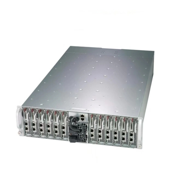
SuperServer 5039MA8/16-H12RFT User's Manual Chapter 1 Introduction 1.1 Overview This chapter provides a brief outline of the functions and features of the 5039MA8/16-H12RFT. The 5039MA8/16-H12RFT is a MicroCloud based on the A2SD1-3750-F/3955F motherboard and the SC939HE-R2K04BP chassis. In addition to the motherboard and chassis, several important parts that are included with the system are listed below. -
Page 9: System Features
Chapter 1: Introduction 1.3 System Features The following table provides an overview of the main features of the 5039MA8/16-H12RFT. Refer to Appendix C for additional specifications. System Features Motherboard 5039MA8-H12RFT: A2SD1-3750-F (8 Cores, 21W TDP) 5039MA16-H12RFT: A2SD1-3955F (16 Cores, 32W TDP) Chassis SC939HE-R2K04BP Intel Atom C3750F/3955F... -
Page 10: Chassis Features
SuperServer 5039MA8/16-H12RFT User's Manual 1.4 Chassis Features Power Button/LED The SC939HE-R2K04BP is a twelve-node chassis. Each node has a main power button that also functions as a status LED. See the table below for LED indications. Node Power Button LED LED Appearance Node Status Green... -
Page 11: Front Features
Chapter 1: Introduction Front Features See Figure 1-2 for the features included on the front of the chassis, and Figure 1-3 for the features included on each node. Figure 1-2. Chassis Front View Front Chassis Features Item Feature Description A removable motherboard node that supports two 3.5" drives or four Node 2.5"... - Page 12 SuperServer 5039MA8/16-H12RFT User's Manual Figure 1-3. Single Node Front View Node Features Item Feature Description UID Button Unit identifier button and LED Power Button Power button and LED Connect the adapter to this port to provide two USB2 ports, and one KVM Port serial port (keyboard/video/mouse connection) Two 10GBaseT LAN (RJ45) ports...
-
Page 13: Rear Features
Chapter 1: Introduction Rear Features The illustration below shows the features included on the rear of the chassis. Figure 1-4. Chassis Rear View Rear Chassis Features Item Feature Description Power Port Use to connect the power supply to a grounded AC power outlet Fans 9-cm exhaust fans provide cooling for the system... -
Page 14: Motherboard Layout
SuperServer 5039MA8/16-H12RFT User's Manual 1.5 Motherboard Layout Below is a layout of the A2SD1-3750-F/3955F with jumper, connector and LED locations shown. See the table on the following page for descriptions. For detailed descriptions, pinout information and jumper settings, refer to Chapter 4. JKVM1: VGA and USB0/1 LAN2 LAN1... -
Page 15: Quick Reference Table
Chapter 1: Introduction Quick Reference Table Jumper Description Default Setting JBR1 BIOS Recovery Pins 1-2 (Normal) JBT1 CMOS Clear Open (Normal) JPG1 VGA Enable/Disable Pins 1-2 (Enabled) JPME1 ME Recovery Pins 1-2 (Normal) JPTG1 10Gb Ethernet Enable/Disable for LAN1/2 Pins 1-2 (Enabled) JVRM1 VRM SMB Clock (to BMC or PCH) Pins 1-2 (Normal) - Page 16 SuperServer 5039MA8/16-H12RFT User's Manual SVID VR13.0/ 12.x SVID 2400/2133/1866/1600MHz Intel U/RDIMM DIMMA0 DDR4 (CHA) DIMMA1 2400/2133/1866/1600MHz PCIe3.0_x4 U/RDIMM PCIe3.0_x2 DIMMB0 S-SATA[5]/ NVMe1 HSIO [8:9] 8.0Gb/s M.2 2280 SATA-III 6Gb/s DDR4 (CHB) SATA-III 1 X2 PCIE3 DIMMB1 6.0Gb/s PCIe3.0_x4 PCIe3.0_x2 PCIe3.0_x8 HSIO [0-7] M.2 2280 HSIO [10:11]...
-
Page 17: Chapter 2 Installation In A Rack
Chapter 2 Installation in a Rack Chapter 2 Installation in a Rack 2.1 Overview This chapter provides advice and instructions for mounting your system in a server rack. If your system is not already fully integrated with drives, fans etc., refer to Chapter 3 for details on installing those specific components. -
Page 18: System Precautions
SuperServer 5039MA8/16-H12RFT User's Manual • Always verify that the rack is stable before extending a server or other component from the rack. • You should extend only one server or component at a time. Extending two or more simul- taneously might cause the rack to become unstable. System Precautions •... -
Page 19: Circuit Overloading
Chapter 2 Installation in a Rack Circuit Overloading Consideration should be given to the connection of the equipment to the power supply circuitry and the effect that any possible overloading of circuits might have on overcurrent protection and power supply wiring. Appropriate consideration of equipment nameplate ratings should be used when addressing this concern. -
Page 20: Installing The Rails
SuperServer 5039MA8/16-H12RFT User's Manual 2.3 Installing the Rails There are a variety of rack units on the market, which may require a slightly different assembly procedure. Also refer to the installation instructions that came with the rack. This rail set fits a rack between 28" and 33.5" deep. Do not use a two post "telco" type rack. 1. -
Page 21: Installing The Server
Chapter 2 Installation in a Rack Figure 2-2. Installing the Left Rail 2.4 Installing the Server 1. If you want to install the optional chassis handles, use screws including a thumbscrew through the bottom hole of each handle. Note: These handles need only be installed when mounting the system into a short rack. - Page 22 SuperServer 5039MA8/16-H12RFT User's Manual Figure 2-3. Installing the Server onto the Rails...
-
Page 23: Chapter 3 Maintenance And Component Installation
Chapter 3: Maintenance and Component Installation Chapter 3 Maintenance and Component Installation This chapter provides instructions on installing and replacing main system components. To prevent compatibility issues, only use components that match the specifications and part numbers given. Remove power from the system or node before installing or replacing components. Refer to Section 3.1. -
Page 24: Accessing The System
SuperServer 5039MA8/16-H12RFT User's Manual 3.2 Accessing the System Top Cover The SC939HE-R2K04BP features a removable top cover, which allows easy access to the inside of the chassis. Removing the Top Cover 1. Remove power from the system as described in Section 3.1. 2. -
Page 25: Removing And Installing Motherboard Nodes
Chapter 3: Maintenance and Component Installation Removing and Installing Motherboard Nodes The chassis features twelve removable nodes. Each node contains a motherboard and hard drives mounted on a sled, allowing for convenient installation and removal. Release Tab Handle Figure 3-2. Removing/Installing a Node Removing Nodes from the System 1. -
Page 26: Connecting To A Node
SuperServer 5039MA8/16-H12RFT User's Manual Connecting to a Node USB and serial port capabilities can be added to any node through the KVM port on the front. Plug in the adapter (pictured below). Figure 3-3. Adapter to Provide USB and Serial Ports... -
Page 27: Motherboard Components
Note: Check the Supermicro website for recommended memory modules. Caution: Exercise extreme care when installing or removing DIMM modules to prevent any possible damage. -
Page 28: Dimm Installation
SuperServer 5039MA8/16-H12RFT User's Manual DIMM Installation JKVM1: VGA 1. Insert DIMM modules in the following USB0/1 order: DIMMA2, DIMMB2, then DIMMA1, LAN2 LAN1 JBT1 SRW3 SRW4 JPTG1:10Gb LAN 1-2:ENABLE 2-3:DISABLE DIMMB1. Use memory modules of the OSC1 JPO1: 1-2:ENABLE 2-3:DISABLE JBR1: JPME1: 1-2:NORMAL... -
Page 29: Motherboard Battery
Chapter 3: Maintenance and Component Installation Motherboard Battery The motherboard uses non-volatile memory to retain system information when system power is removed. This memory is powered by a lithium battery residing on the motherboard. Replacing the Battery Begin by removing power from the system as described in Section 3.1, and remove the cover as described in Section 3.2. -
Page 30: Chassis Components
SuperServer 5039MA8/16-H12RFT User's Manual 3.4 Chassis Components Hard Drives The hard drives are installed directly to the node tray. For this reason, hard drives are not hot-swappable as the tray must be removed from the system. It supports two 3.5", four 2.5", or a combination of one 3.5"... - Page 31 Chapter 3: Maintenance and Component Installation Figure 3-6. Installing 2.5" HDDs Note: Enterprise level hard disk drives are recommended for use in Supermicro chassis and servers. For information on recommended HDDs, visit the Supermicro website at http://www. supermicro.com/products/nfo/storage.cfm.
-
Page 32: System Cooling
SuperServer 5039MA8/16-H12RFT User's Manual System Cooling Corresponding Nodes and Fans The 5039MA8/16-H12RFT has four fans. By default, there is one fan zone for the entire system. This may be changed to two fan zones by opening jumper JP37 on the HDD backplane. -
Page 33: Replacing Fans
Chapter 3: Maintenance and Component Installation Replacing Fans Four 9-cm fans circulate air through the chassis to lower the internal temperature. These fans are designed to be easily changed, with no tools required and no need to remove any other parts inside the chassis. Replacing a Fan 1. -
Page 34: Air Shroud
SuperServer 5039MA8/16-H12RFT User's Manual Air Shroud The air shroud is used to concentrate airflow to maximize fan efficiency. Installing the Air Shroud 1. Remove the node from the chassis onto a flat, non-conductive surface. 2. If necessary, move any cables that interfere with the air shroud placement. 3. -
Page 35: Power Supply
The chassis features redundant power supplies. They are hot-swappable, meaning they can be changed without powering down the system. New units can be ordered directly from Supermicro or authorized distributors. These power supplies are auto-switching capable. This feature enables them to automatically sense the input voltage and operate at a 100-120V or 180-240V. -
Page 36: Chapter 4 Motherboard Connections
I-SATA0 and I-SATA1 for 3.5" hard drive connection. Note 1: I-SATA6 is a Supermicro SuperDOM. This is a yellow SATA DOM connector with power pins built in and do not require separate external power cables. This connector is backward-compatible with non-Supermicro SATADOMs that require an external power supply. - Page 37 Serial Link DOM devices. DOM Power Pin Definitions Pin# Definition Ground Ground SATA Ports The A2SD1-3750F/3955F has two SATA 3.0 ports. I-SATA2 supports SuperDOM, Supermicro's proprietary SATA DOM with a built-in power connection.
-
Page 38: Ports
SuperServer 5039MA8/16-H12RFT User's Manual M.2 Slot M.2 is formerly known as Next Generation Form Factor (NGFF). The A2SD1-3750F/3955F has two M.2 PCI-E 3.0 slots that support M-key 2280 SSD/NVMe. Backplane Connector The backplane connector at J4 provides four SATA 3.0 connections or two NVMe PCI-E 3.0 x4 connections. - Page 39 Note: UID can also be triggered via IPMI on the motherboard. For more information on IPMI, please refer to the IPMI User's Guide posted on our website at https://www.supermicro.com/ products/nfo/IPMI.cfm. UID LED...
-
Page 40: Jumpers
SuperServer 5039MA8/16-H12RFT User's Manual 4.4 Jumpers Explanation of Jumpers To modify the operation of the motherboard, jumpers are used to choose between optional settings. Jumpers create shorts between two pins to change the function associated with it. Pin 1 is identified with a square solder pad on the printed circuit board. See the motherboard layout page for jumper locations. - Page 41 Chapter 4: Motherboard Connections VGA Enable/Disable Use JPG1 to enable or disable the VGA port using the onboard graphics controller. The default setting is Enabled. VGA Enable/Disable Jumper Settings Jumper Setting Definition Pins 1-2 Enabled Pins 2-3 Disabled Management Engine (ME) Recovery Use jumper JPME1 to select ME Firmware Recovery mode, which will limit resource allocation for essential system operation only in order to maintain normal power operation and management.
-
Page 42: Led Indicators
SuperServer 5039MA8/16-H12RFT User's Manual C Bus for VRM Jumpers JVRM1 and JVRM2 allow the BMC or the PCH to access CPU and memory VRM controllers. Refer to the table below for jumper settings. Jumper Settings Jumper Setting Definition Pins 1-2 BMC (Normal) Pins 2-3 BIOS Recovery... - Page 43 Chapter 4: Motherboard Connections Onboard Power LED LED1 is an Onboard Power LED. When this LED is lit, it means power is present on the motherboard. In suspend mode, this LED will blink on and off. Turn off the system and unplug the power cord before removing or installing components.
-
Page 44: Chapter 5 Software
USB/SATA DVD drive, or a USB flash drive, or the IPMI KVM console. 2. Retrieve the proper RST/RSTe driver. Go to the Supermicro web page for your motherboard and click on "Download the Latest Drivers and Utilities", select the proper driver, and copy it to a USB flash drive. - Page 45 Chapter 5: Software 4. During Windows Setup, continue to the dialog where you select the drives on which to install Windows. If the disk you want to use is not listed, click on “Load driver” link at the bottom left corner. Figure 5-2.
-
Page 46: Driver Installation
The Supermicro website contains drivers and utilities for your system at https://www. supermicro.com/wftp/driver. Some of these must be installed, such as the chipset driver. After accessing the website, go into the CDR_Images (in the parent directory of the above link) and locate the ISO file for your motherboard. Download this file to to a USB flash drive or a DVD. -
Page 47: Superdoctor ® 5
5.3 SuperDoctor ® The Supermicro SuperDoctor 5 is a program that functions in a command-line or web-based interface for Windows and Linux operating systems. The program monitors such system health information as CPU temperature, system voltages, system power consumption, fan speed, and provides alerts via email or Simple Network Management Protocol (SNMP). -
Page 48: Ipmi
The A2SD1-3750-F/3955F supports the Intelligent Platform Management Interface (IPMI). IPMI is used to provide remote access, monitoring and management. There are several BIOS settings that are related to IPMI. For general documentation and information on IPMI, please visit our website at: http://www.supermicro.com/products/nfo/IPMI.cfm. -
Page 49: Chapter 6 Uefi Bios
Chapter 4: BIOS Chapter 6 UEFI BIOS 6.1 Introduction This chapter describes the AMIBIOS™ Setup utility for the A2SD1-3750-F/3955F motherboard. The BIOS is stored on a chip and can be easily upgraded using a flash program. Note: Due to periodic changes to the BIOS, some settings may have been added or deleted and might not yet be recorded in this manual. -
Page 50: Main Setup
Note: The time is in the 24-hour format. For example, 5:30 P.M. appears as 17:30:00. The date's default value is the BIOS build date after RTC reset. Supermicro A2SD1-3750F BIOS Version This item displays the version of the BIOS ROM used in the system. - Page 51 Chapter 4: BIOS Memory Information Total Memory This item displays the total size of memory available in the system. Memory Speed This item displays the default speed of the memory modules installed in the system.
-
Page 52: Advanced
SuperServer 5039MA8/16-H12RFT User's Manual 6.3 Advanced Use the arrow keys to select Advanced setup and press <Enter> to access the submenu items: Warning: Take caution when changing the Advanced settings. An incorrect value, a very high DRAM frequency or an incorrect BIOS timing setting may cause the system to malfunction. When this occurs, restore to default manufacturer settings. - Page 53 Chapter 4: BIOS Wait For "F1" If Error This feature forces the system to wait until the F1 key is pressed if an error occurs. The options are Disabled and Enabled. INT19 (Interrupt 19) Trap Response Interrupt 19 is the software interrupt that handles the boot disk function. When this item is set to Immediate, the ROM BIOS of the host adaptors will "capture"...
- Page 54 SuperServer 5039MA8/16-H12RFT User's Manual • Microcode Revision • Processor Frequency • CPU BCLK Frequency • L1 Cache RAM • L2 Cache RAM EIST (GV3) EIST (Enhanced Intel SpeedStep Technology) allows the system to automatically adjust processor voltage and core frequency to reduce power consumption and heat dissipation. The options are Disable and Enable.
- Page 55 Chapter 4: BIOS Max Core C-State Use this feature to specify which idle power saving state to enter. The options are C1 and C6. Enhanced Halt State (C1E) Select Enable to enable Enhanced Halt State support, which will significantly reduce the CPU's power consumption by minimizing the CPU's clock cycles and voltage use during a Halt State.
- Page 56 SuperServer 5039MA8/16-H12RFT User's Manual Virtualization Technology Select Enable to use Intel Virtualization Technology to allow one platform to run multiple operating systems and applications in independent partitions, creating multiple virtual systems in one physical computer. The options are Disable and Enable. Extended APIC (Advanced Programmable Interrupt Controller) Based on the Intel Hyper-Threading technology, each logical processor (thread) is assigned 256 APIC IDs (APIDs) in 8-bit bandwidth.
- Page 57 Chapter 4: BIOS • MRC Version • Total Memory • Memory Frequency VT-d Select Enabled to enable Intel Virtualization Technology support for Direct I/O VT-d by reporting the I/O device assignments to VMM through the DMAR ACPI Tables. This feature offers fully-protected I/O resource-sharing across the Intel platforms, providing the user with greater reliability, security and availability in networking and data-sharing.
- Page 58 SuperServer 5039MA8/16-H12RFT User's Manual PMC reset Enable this feature to receive a notification when there is a global reset because of an SMBus slave power down. The options are Disabled and Enabled. Power Button Override When this feature is set to Enabled, it sends a notification when there is a power but- ton override.
- Page 59 Chapter 4: BIOS Interleaving Set this feature to Enabled for NVDIMM interleaving support. Interleaving is a technique that increases memory speed. The options are Disabled and Enabled. Restore When this feature is set to Enabled, data is restored to NVDIMM after a system power- up.
- Page 60 SuperServer 5039MA8/16-H12RFT User's Manual Patrol Scrub Enable Patrol Scrubbing is a process that allows the CPU to correct correctable memory errors detected in a memory module and send the correction to the requestor (the original source). When this item is set to Enable, the IO hub will read and write back one cache line every 16K cycles if there is no delay caused by internal processing.
- Page 61 Chapter 4: BIOS Scrambler This feature scrambles data in the memory and makes it inaccessible. The options are Disabled and Enabled. Slow Power Down Exit Use this feature to enable or disable the slow exit after the precharge power down. The options are Disable dand Enabled.
- Page 62 SuperServer 5039MA8/16-H12RFT User's Manual Flexible I/O Selection Use this feature to configure the I/O signal as PCI-E or SATA. The options are U.2 + M.2-1 + SATA [15], M.2 + SATA, and U.2 + SATA[18:19]. SATA Configuration SATA0 SATA 0 Enable controller Use this feature to enable or disable the onboard SATA controller supported by the processor.
- Page 63 Chapter 4: BIOS SATA1 SATA 1 Enable controller Use this feature to enable or disable the onboard SATA controller supported by the Intel PCH chip. The options are Enabled and Disabled. SATA 1 LPM (Link Power Management) When this item is set to Enabled, the SATA AHCI controller manages the power usage of the SATA link.
- Page 64 SuperServer 5039MA8/16-H12RFT User's Manual • Backup Firmware Version • Recovery Firmware Version • ME Firmware Features • ME Firmware Status #1 • ME Firmware Status #2 • Current State • Error Code PCIe/PCI/PnP Configuration The following PCI information will be displayed: •...
- Page 65 Chapter 4: BIOS ASPM Support Use this item to set the Active State Power Management (ASPM) level for a PCI-E device. Select Auto for the system BIOS to automatically set the ASPM level based on the system configuration. Select Disabled to disable ASPM support. The options are Disabled, Auto, and Force L0s.
- Page 66 SuperServer 5039MA8/16-H12RFT User's Manual PXE Boot Wait Time Use this feature to select the wait time to press the ESC key to abort the PXE boot. The default is 0. Media Detect Count Use this feature to select the wait time in seconds to detect LAN media. The default is 1. Super IO Configuration ...
- Page 67 Chapter 4: BIOS COM1 Console Redirection Settings COM1 Terminal Type This feature allows the user to select the target terminal emulation type for Console Redirection. Select VT100 to use the ASCII Character set. Select VT100+ to add color and function key support. Select ANSI to use the Extended ASCII Character Set. Select VT-UTF8 to use UTF8 encoding to map Unicode characters into one or more bytes.
- Page 68 SuperServer 5039MA8/16-H12RFT User's Manual COM1 Recorder Mode Select Enabled to capture the data displayed on a terminal and send it as text messages to a remote server. The options are Disabled and Enabled. COM1 Resolution 100x31 Select Enabled for extended-terminal resolution support. The options are Disabled and Enabled.
- Page 69 Chapter 4: BIOS SOL Parity A parity bit can be sent along with regular data bits to detect data transmission errors. Select Even if the parity bit is set to 0, and the number of 1's in data bits is even. Select Odd if the parity bit is set to 0, and the number of 1's in data bits is odd.
- Page 70 SuperServer 5039MA8/16-H12RFT User's Manual OS Redirection Resolution Use this feature to select the number of rows and columns used in Console Redirection for legacy OS support. The options are 80x24 and 80x25. Redirection After POST Use this feature to enable or disable legacy console redirection after BIOS POST. When set to BootLoader, legacy console redirection is disabled before booting the OS.
- Page 71 Chapter 4: BIOS Bits Per Second This feature sets the transmission speed for a serial port used in Console Redirection. Make sure that the same speed is used in the host computer and the client computer. A lower transmission speed may be required for long and busy lines. The options are 9600, 19200, 57600, and 115200 (bits per second).
- Page 72 SuperServer 5039MA8/16-H12RFT User's Manual Trusted Computing (Available when a TPM device is installed and detected by the BIOS) The following Trusted Platform Module (TPM) information will display if a TPM 2.0 module is detected: TPM20 Device Found Vendor Firmware Version Security Device Support If this feature and the TPM jumper on the motherboard are both set to Enable, onboard security devices will be enabled for TPM (Trusted Platform Module) support to enhance data...
- Page 73 Chapter 4: BIOS Endorsement Hierarchy Use this feature to disable or enable endorsement hierarchy for privacy control. The options are Disabled and Enabled. TPM2.0 UEFI Spec Version Use this feature to specify the TPM UEFI spec version. TCG 1.2 supports Windows® 2012, Windows 8, and Windows 10.
- Page 74 SuperServer 5039MA8/16-H12RFT User's Manual Blink LEDs This feature allows the user to specify the duration for LEDs to blink. The range is from 0 ~ 15 seconds. The default setting is 0. Port Configuration Information This section displays the following port information: •...
-
Page 75: Event Logs
Chapter 4: BIOS 6.4 Event Logs Use this menu to configure Event Log settings. Change SMBIOS Event Log Settings Enabling/Disabling Options PCIe ELog Support Use this feature to enable or disable PCIe error logging suport. The options are Disabled and Enabled. Memory ELog Support Use this feature to enable or disable memory error logging suport. - Page 76 SuperServer 5039MA8/16-H12RFT User's Manual Erasing Settings Erase Event Log Select Enabled to erase all error events in the SMBIOS (System Management BIOS) log before an event logging is initialized at bootup. The options are No, Yes, Next reset, and Yes, Every reset. When Log is Full Select Erase Immediately to immediately erase all errors in the SMBIOS event log when the event log is full.
-
Page 77: Ipmi
Chapter 4: BIOS 6.5 IPMI Use this menu to configure Intelligent Platform Management Interface (IPMI) settings. BMC Firmware Revision This item indicates the IPMI firmware revision used in your system. IPMI Status This item indicates the status of the IPMI firmware installed in your system. System Event Log Enabling/Disabling Options SEL Components... - Page 78 SuperServer 5039MA8/16-H12RFT User's Manual When SEL is Full This feature allows the user to determine what the BIOS should do when the system event log is full. Select Erase Immediately to erase all events in the log when the system event log is full.
- Page 79 The Disable option is for applications that require faster power on time wthout using Supermicro Update Manager (SUM) or extended IPMI features. The BMC network configuration in the BIOS setup is also invalid when IPMI Function Support is disabled.
-
Page 80: Security
SuperServer 5039MA8/16-H12RFT User's Manual 6.6 Security Use this menu to configure the following security settings for the system. Password Check Select Setup for the system to check for a password at Setup. Select Always for the system to check for a password at bootup or upon entering the BIOS Setup utility. The options are Setup and Always. - Page 81 Chapter 4: BIOS CSM Support This feature is for manufacturing debugging purposes. *If Secure Boot Mode is set to Custom, Key Management features are available for configuration: Reset to Setup Mode Select Yes to delete all Secure Boot key databases and force the system to Setup Mode. The options are Yes and No.
- Page 82 SuperServer 5039MA8/16-H12RFT User's Manual Authorized Signatures Set New Select Yes to load the database from the manufacturer's defaults. Select No to load the DB from a file. The options are Yes and No. Append Select Yes to add the database from the manufacturer's defaults to the existing DB. Select No to load the DB from a file.
-
Page 83: Boot
Chapter 4: BIOS 6.7 Boot Use this menu to configure Boot Settings: Boot Configuration Boot Mode Select Use this feature to select the boot mode. The options are LEGACY, UEFI, and DUAL. Fixed Boot Order Priorities This option prioritizes the order of bootable devices that the system to boot from. Press <Enter>... - Page 84 SuperServer 5039MA8/16-H12RFT User's Manual UEFI Application Boot Priorities • Boot Option # - This feature sets the system boot order of detected devices. The options are [the list of detected boot device(s)] and Disabled. UEFI NETWORK Drive BBS Priorities •...
-
Page 85: Save & Exit
Chapter 4: BIOS 6.8 Save & Exit Select the Save & Exit tab from the BIOS setup screen to configure the settings below. Save Options Save Changes and Reset When you have completed the system configuration changes, select this feature to save all changes made and reset the system. - Page 86 SuperServer 5039MA8/16-H12RFT User's Manual Default Options Restore Optimized Defaults To set this feature, select Restore Optimized Defaults and press <Enter>. These are factory settings designed for maximum system performance but not for maximum stability. Save as User Defaults To set this feature, select Save as User Defaults from the Exit menu and press <Enter>. This enables the user to save any changes to the BIOS setup for future use.
- Page 87 Appendix A: BIOS Codes Appendix A BIOS Codes A.1 BIOS Error POST (Beep) Codes During the POST (Power-On Self-Test) routines, which are performed each time the system is powered on, errors may occur. Non-fatal errors are those which, in most cases, allow the system to continue the boot-up process.
- Page 88 When BIOS performs the Power On Self Test, it writes checkpoint codes to I/O port 0080h. If the computer cannot complete the boot process, a diagnostic card can be attached to the computer to read I/O port 0080h (Supermicro p/n AOC-LPC80-20). For information on AMI updates, please refer to http://www.ami.com/products/.
- Page 89 Supermicro's Technical Support department for assistance. Only certified technicians should attempt to install or configure components. Read this appendix in its entirety before installing or configuring components in the Supermicro chassis. These warnings may also be found on our website at http://www.supermicro.com/about/...
- Page 90 Appendix B: Standardized Warning Statements Warnung WICHTIGE SICHERHEITSHINWEISE Dieses Warnsymbol bedeutet Gefahr. Sie befinden sich in einer Situation, die zu Verletzungen führen kann. Machen Sie sich vor der Arbeit mit Geräten mit den Gefahren elektrischer Schaltungen und den üblichen Verfahren zur Vorbeugung vor Unfällen vertraut. Suchen Sie mit der am Ende jeder Warnung angegebenen Anweisungsnummer nach der jeweiligen Übersetzung in den übersetzten Sicherheitshinweisen, die zusammen mit diesem Gerät ausgeliefert wurden.
- Page 91 SuperServer 5039MA8/16-H12RFT User's Manual . ٌ ا ك ً ف حالة و ٌ يك أى تتسبب ف اصابة جسذ ة ٌ هذا الزهز ع ٌ خطز !تحذ ز قبل أى تعول عىل أي هعذات،يك عىل علن بالوخاطز ال ا ٌجوة عي الذوائز ٍ...
- Page 92 Appendix B: Standardized Warning Statements Warnung Vor dem Anschließen des Systems an die Stromquelle die Installationsanweisungen lesen. ¡Advertencia! Lea las instrucciones de instalación antes de conectar el sistema a la red de alimentación. Attention Avant de brancher le système sur la source d'alimentation, consulter les directives d'installation. .יש...
- Page 93 SuperServer 5039MA8/16-H12RFT User's Manual Warnung Dieses Produkt ist darauf angewiesen, dass im Gebäude ein Kurzschluss- bzw. Überstromschutz installiert ist. Stellen Sie sicher, dass der Nennwert der Schutzvorrichtung nicht mehr als: 250 V, 20 A beträgt. ¡Advertencia! Este equipo utiliza el sistema de protección contra cortocircuitos (o sobrecorrientes) del edificio.
- Page 94 Appendix B: Standardized Warning Statements Power Disconnection Warning Warning! The system must be disconnected from all sources of power and the power cord removed from the power supply module(s) before accessing the chassis interior to install or remove system components. 電源切断の警告...
- Page 95 SuperServer 5039MA8/16-H12RFT User's Manual يجب فصم اننظاو من جميع مصادر انطاقت وإ ز انت سهك انكهرباء من وحدة امداد انطاقت قبم انىصىل إىن امنناطق انداخهيت نههيكم نتثبيج أو إ ز انت مكىناث الجهاز 경고! 시스템에 부품들을 장착하거나 제거하기 위해서는 섀시 내부에 접근하기 전에 반드시 전원 공급장치로부터...
- Page 96 Appendix B: Standardized Warning Statements Attention Il est vivement recommandé de confier l'installation, le remplacement et la maintenance de ces équipements à des personnels qualifiés et expérimentés. !אזהרה .צוות מוסמך בלבד רשאי להתקין, להחליף את הציוד או לתת שירות עבור הציוד واملدربيه...
- Page 97 SuperServer 5039MA8/16-H12RFT User's Manual Warnung Diese Einheit ist zur Installation in Bereichen mit beschränktem Zutritt vorgesehen. Der Zutritt zu derartigen Bereichen ist nur mit einem Spezialwerkzeug, Schloss und Schlüssel oder einer sonstigen Sicherheitsvorkehrung möglich. ¡Advertencia! Esta unidad ha sido diseñada para instalación en áreas de acceso restringido. Sólo puede obtenerse acceso a una de estas áreas mediante la utilización de una herramienta especial, cerradura con llave u otro medio de seguridad.
- Page 98 Appendix B: Standardized Warning Statements Battery Handling Warning! There is the danger of explosion if the battery is replaced incorrectly. Replace the battery only with the same or equivalent type recommended by the manufacturer. Dispose of used batteries according to the manufacturer's instructions 電池の取り扱い...
- Page 99 SuperServer 5039MA8/16-H12RFT User's Manual هناك خطر من انفجار يف حالة اسحبذال البطارية بطريقة غري صحيحة فعليل اسحبذال البطارية فقط بنفس النىع أو ما يعادلها مام أوصث به الرشمة املصنعة جخلص من البطاريات املسحعملة وفقا لحعليامت الرشمة الصانعة 경고! 배터리가 올바르게 교체되지 않으면 폭발의 위험이 있습니다. 기존 배터리와 동일하거나 제 조사에서...
- Page 100 Appendix B: Standardized Warning Statements ¡Advertencia! Puede que esta unidad tenga más de una conexión para fuentes de alimentación. Para cortar por completo el suministro de energía, deben desconectarse todas las conexiones. Attention Cette unité peut avoir plus d'une connexion d'alimentation. Pour supprimer toute tension et tout courant électrique de l'unité, toutes les connexions d'alimentation doivent être débranchées.
- Page 101 SuperServer 5039MA8/16-H12RFT User's Manual Backplane Voltage Warning! Hazardous voltage or energy is present on the backplane when the system is operating. Use caution when servicing. バックプレーンの電圧 システムの稼働中は危険な電圧または電力が、 バックプレーン上にかかっています。 修理する際には注意く ださい。 警告 当系统正在进行时,背板上有很危险的电压或能量,进行维修时务必小心。 警告 當系統正在進行時,背板上有危險的電壓或能量,進行維修時務必小心。 Warnung Wenn das System in Betrieb ist, treten auf der Rückwandplatine gefährliche Spannungen oder Energien auf.
- Page 102 Appendix B: Standardized Warning Statements هناك خطز مه التيار الكهزبايئ أوالطاقة املىجىدة عىل اللىحة عندما يكىن النظام يعمل كه حذ ر ا عند خدمة هذا الجهاس 경고! 시스템이 동작 중일 때 후면판 (Backplane)에는 위험한 전압이나 에너지가 발생 합니다. 서비스 작업 시 주의하십시오. Waarschuwing Een gevaarlijke spanning of energie is aanwezig op de backplane wanneer het systeem in gebruik is.
- Page 103 SuperServer 5039MA8/16-H12RFT User's Manual תיאום חוקי החשמל הארצי !אזהרה .התקנת הציוד חייבת להיות תואמת לחוקי החשמל המקומיים והארציים تركيب املعدات الكهربائية يجب أن ميتثل للقىاويه املحلية والىطىية املتعلقة بالكهرباء 경고! 현 지역 및 국가의 전기 규정에 따라 장비를 설치해야 합니다. Waarschuwing Bij installatie van de apparatuur moet worden voldaan aan de lokale en nationale elektriciteitsvoorschriften.
- Page 104 Appendix B: Standardized Warning Statements Attention La mise au rebut ou le recyclage de ce produit sont généralement soumis à des lois et/ou directives de respect de l'environnement. Renseignez-vous auprès de l'organisme compétent. סילוק המוצר !אזהרה .סילוק סופי של מוצר זה חייב להיות בהתאם להנחיות וחוקי המדינה التخلص...
- Page 105 SuperServer 5039MA8/16-H12RFT User's Manual Warnung Gefährlich Bewegende Teile. Von den bewegenden Lüfterblätter fern halten. Die Lüfter drehen sich u. U. noch, wenn die Lüfterbaugruppe aus dem Chassis genommen wird. Halten Sie Finger, Schraubendreher und andere Gegenstände von den Öffnungen des Lüftergehäuses entfernt.
- Page 106 Verbindungskabeln, Stromkabeln und/oder Adapater, die Ihre örtlichen Sicherheitsstandards einhalten. Der Gebrauch von anderen Kabeln und Adapter können Fehlfunktionen oder Feuer verursachen. Die Richtlinien untersagen das Nutzen von UL oder CAS zertifizierten Kabeln (mit UL/CSA gekennzeichnet), an Geräten oder Produkten die nicht mit Supermicro gekennzeichnet sind.
- Page 107 حجم املوصل والقابس السليم. استخدام أي كابالت ومحوالت أخرى قد يتسبب يف عطل أو حريق. يحظر قانون السالمة لألجهزة الكهربائية واملعدات استخدام الكابالت املعتمدة من قبلUL أوCSA ( والتي تحمل عالمةUL/CSA) مع أي معدات أخرى غري املنتجات املعنية واملحددة من قبلSupermicro.
- Page 108 사항을 준수하여 제공되거나 지정된 연결 혹은 구매 케이블, 전원 케이블 및 AC 어댑터를 사용하십시오. 다른 케이블이나 어댑터를 사용하면 오작동이나 화재가 발생할 수 있습니다. 전기 용품 안전법은 UL 또는 CSA 인증 케이블 (코드에 UL / CSA가 표시된 케이블)을 Supermicro 가 지정한 제품 이외의 전기 장치에 사용하는 것을 금지합니다. Stroomkabel en AC-Adapter...
- Page 109 Appendix C: System Specifications Appendix C System Specifications Processors Single Intel Atom C3750F/3955F in an FCBGA1310 type socket, CPU TDP supports 21W/32W Note: Please refer to the motherboard specifications pages on our website for updates to supported processors. Chipset Intel C3000 SoC chipset (System-On-Chip) BIOS 128 Mb AMI®...
- Page 110 SuperServer 5039MA8/16-H12RFT User's Manual Regulatory Compliance Electromagnetic Emissions: FCC Class A, EN 55032 Class A, EN 61000-3-2/3-3, CISPR 32 Class A Electromagnetic Immunity: EN 55024/CISPR 24, (EN 61000-4-2, EN 61000-4-3, EN 61000-4-4, EN 61000-4-5, EN 61000-4-6, EN 61000-4-8, EN 61000-4-11) Safety: CSA/EN/IEC/UL 60950-1 Compliant, UL or CSA Listed (USA and Canada), CE Marking (Europe) Other: VCCI-CISPR 32 and AS/NZS CISPR 32 Environmental: Directive 2011/65/EU and Directive 2012/19/EU...
- Page 111 Warning: Do not upgrade the BIOS unless your system has a BIOS-related issue. Flashing the wrong BIOS can cause irreparable damage to the system. In no event shall Supermicro be liable for direct, indirect, special, incidental, or consequential damages arising from a BIOS update.
- Page 112 USB device or a writable CD/DVD. Note 1: If you cannot locate the "Super.ROM" file in your drive disk, visit our website at www.supermicro.com to download the BIOS package. Extract the BIOS binary image into a USB flash device and rename it "Super.ROM" for the BIOS recovery use.
- Page 113 Appendix D: UEFI BIOS Recovery 3. After locating the healthy BIOS binary image, the system will enter the BIOS Recovery menu as shown below. Note: At this point, you may decide if you want to start the BIOS recovery. If you decide to proceed with BIOS recovery, follow the procedures below.
- Page 114 SuperServer 5039MA8/16-H12RFT User's Manual 5. After the BIOS recovery process is complete, press any key to reboot the system. 6. Using a different system, extract the BIOS package into a USB flash drive. 7. Press <Del> continuously during system boot to enter the BIOS Setup utility. From the top of the tool bar, select Boot to enter the submenu.
- Page 115 Appendix D: UEFI BIOS Recovery 8. When the UEFI Shell prompt appears, type fs# to change the device directory path. Go to the directory that contains the BIOS package you extracted earlier from Step 6. Enter flash.nsh BIOSname.### at the prompt to start the BIOS update process. Note: Do not interrupt this process until the BIOS flashing is complete.
Need help?
Do you have a question about the SuperServer 5039MA8-H12RFT and is the answer not in the manual?
Questions and answers