Table of Contents
Advertisement
Quick Links
NMC-64 USER & INSTALLATION
Manual version:
Date of issue:
Publisher:
© Copyright 2003, Netafim
No part of this publication may be reproduced, stored in an automated data file or
made public in any form or by any means, whether electronic, mechanical, by
photocopying, recording or in any other manner without prior written permission of the
publisher.
Although Netafim takes the greatest possible care both with its products and the
associated manuals, there may be deficiencies in them.
Netafim will not however accept responsibility for damage resulting from the use of
Netafim products or damage resulting from the use of this manual. Netafim also
reserves the right to make changes and improvements to its products or to the
associated manuals without notice.
MANUAL
2.00
January 2005
TM
Netafim
(A.C.S.) Ltd.
1
Advertisement
Table of Contents
Troubleshooting

Related Manuals for Netafim NMC-64


Summary of Contents for Netafim NMC-64
-
Page 1: Table Of Contents
Although Netafim takes the greatest possible care both with its products and the associated manuals, there may be deficiencies in them. Netafim will not however accept responsibility for damage resulting from the use of Netafim products or damage resulting from the use of this manual. -
Page 2: Table Of Contents
Table of contents Table of contents ......................1 Introduction .........................6 General Description......................6 Main Features........................6 Operation of the NMC-64..................... 7 Main Menu Screen........................... 8 Use of the keypad: .......................... 8 Use of keypad buttons: ........................9 Hot Screens........................10 Hot Screen 0 ..........................10 Hot Screen 1 .......................... - Page 3 User & Installation Manual Table Of Contents 2.3 START/STOP VALVE.......................35 2.4 FILTER FLUSHING........................35 3. ALARM ..........................36 3.1 ALARM RESET.........................36 3.2 HISTORY...........................37 3.3 ALARM DEFINITION ........................37 3.4 ALARM SETTING ........................39 4. HISTORY ......................... 40 4.1 IRRIGATION LOG........................40 4.2 UNCOMPLETED IRRIGATION....................41 4.3 UNCOMPLETED PROGRAMS....................42 4.4 DAILY IRRIGATION........................42 4.5 IRRIGATION ACCUMULATION ....................43...
- Page 4 NMC-64 Irrigation 7. CONFIGURATION ......................58 7.1 DEVICE DELAY CONFIGURATION ..................58 7.2 PUMP CONFIGURATION ......................59 7.3 VALVE CONFIGURATION....................... 60 7.4 VALVE FLOW RATE........................ 60 7.5 WATER METER ........................61 7.6 DOSING CHANNEL CONFIGURATION.................. 61 7.7 DOSING CONFIGURATION ....................63 7.8 EC/pH RANGE DEFINITION....................
- Page 5 EC Transmitter & Sensor connection and calibration............ 93 Connecting EC sensor to Transmitter:..................93 EC Transmitter Calibration ......................93 Connecting EC transmitter to NMC-64 controller ..............94 pH Transmitter & Sensor connection and calibration............ 96 Connecting pH sensor to Transmitter:..................96 pH Transmitter Calibration ......................97 Connecting pH transmitter to NMC-64 controller...............97...
-
Page 6: Introduction
Once the controller is configured all relevant menus will be available for use. General Description • The Netafim NMC-64 is a top of the line irrigation controller made of the latest and most updated technology. • The NMC-64 is a modular flexible controller with many customizable features: Output Card Options for 24VAC, Dry Contact. -
Page 7: Operation Of The Nmc-64
• Up to 22 Analog Inputs (Cards of 11 inputs each) Operation of the NMC-64 Operating the NMC-64 is very simple and defined to be intuitive. Use the following guideline for easy operation: • To change specific settings navigate the cursor (flashing underline mark) using the arrows until it is under the relevant setting. -
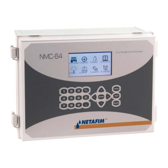
Page 8: Main Menu Screen
NMC-64 Irrigation Main Menu Screen Press the MENU key a few times until you reach the Main Menu screen. The main menu screen consists of eight icons. The navigation between icons is done using the arrow keys; the selected icon will be highlighted and can be entered by pressing the Enter button. -
Page 9: Use Of Keypad Buttons
User & Installation Manual Introduction Use of keypad buttons: Help Using the Help key you can access help screens and graphs. If not indicated otherwise press the ‘Menu’ key to exit the ‘Help’ menu. Menu The Menu key is used to exit screens and menus you are currently in. -
Page 10: Hot Screens
NMC-64 Irrigation Hot Screens The NMC-64 incorporates 8 keys that enable you to access quick information of actual and future processes as well as general conditions. To enter the Hot Screens go to the Main Menu screen and press the Menu button, you will enter you default Hot Screen. -
Page 11: Hot Screen 1
User & Installation Manual Introduction Hot Screen 1 Hot screen 1 displays a summary of active processes, irrigation programs, important messages, and the time and date. • NEXT IRRIGATION – Displays next irrigation data: • CYCLE – Displays how many cycles are set, which cycle is currently active and how many are remaining. -
Page 12: Hot Screen 3 - Program Status
NMC-64 Irrigation IRRIGATION PROCESS Prog:1 Valve:1 Time:10:00 Functions Program Actual Flow Valve Water 00:10 00:01 5.000 Fert.1 2.00 0.09 60.000 Fert.2 2.00 0.09 60.000 Fert.3 2.00 0.09 60.000 • Functions - Active functions for current irrigation. • Program - Total quantity or time to be given during the current irrigation. -
Page 13: Hot Screen 4 - Water / Ec/Ph / Fert
User & Installation Manual Introduction • Status - Cycle status: • End - All of the cycles are done. • Wait - In between cycles (Delay Time). • Irrig - Irrigation is active. • Next Start - When Status is "Wait" row will show the time for next irrigation. •... -
Page 14: Hot Screen 5 - Filter Flushing Status
(%) cannot be higher than the Max(%) and cannot be lower than the Min (%), if it is identical to one of them than the NMC-64 controller will not be able to reach desired EC/pH values and the fertilizer program setting must be rechecked. -
Page 15: Hot Screen 6 - Temperature And Humidity
User & Installation Manual Introduction • Flush Status - Indication whether filter flushing is active (On/Off/Waiting). • Time To Next Flush (hh:mm:ss) – Remaining time until next filter flushing will occur. This time is only counted when irrigation is active. •... -
Page 16: Hot Screen 7 - Weather Station
NMC-64 Irrigation Hot Screen 7 – Weather station Hot screen 7 shows the measured values of the weather station sensors (outside conditions). להוסיף שרטוט של המסך... -
Page 17: Software
Software Software Getting started This paragraph briefly explains how to get started with the NMC-64 software setup procedure. For further explanations please see the detailed instructions per table. For initial configuration of the controller start with Menu 8. Install. Later steps might depend on earlier ones; therefore it is essential to go through all the steps. -
Page 18: Program
NMC-64 Irrigation Table NMC64 Table description Test Relays Verify the functionality of each output/device. Program Water Run Time Define water programs; method (quantity/time), total water quantity/time, water before and water after. Notice: water before/after are deducted from total water quantity/time. -
Page 19: Irrigation
The Irrigation Program screen consists of all settings for automatic irrigation starts. It depends heavily on the Water Run Time and Dosing Program screens and therefore they must be filled before irrigation can actually take place. The NMC-64 consists of 15 irrigation programs. IRRIGATION PROGRAM Program: Priority Const. - Page 20 Run Time is 30 minutes and the Delay is 45 minutes the second cycle will start 15 minutes after the end of the first cycle. • Valve # - The NMC-64 can operate valves in any required order; set the valve number, press enter, the following window will appear: Select ‘–‘...
- Page 21 User & Installation Maunal Software 40 valves in any required order (all of them together, one after the other, a few groups, etc’). • Run Time # – attach a Run Time Program to a valve or a group of valves. When setting valves to work individually, a Run Time Program should be set for each valve.
-
Page 22: Water Run Time
NMC-64 Irrigation Setting an irrigation that is longer than 24H: An active irrigation will not change when the irrigation is longer than 24 hours there will be no changes in current sequence according to Cycle Days. Example 1: If cycle days is 1 and the irrigation length is 30 hours, the irrigation will repeat itself every 30 hours, so that it will be continues irrigation. -
Page 23: Dosing
P.Qty 0.00 0.00 The NMC-64 includes 10 predefined dosing programs. Each program can operate according to one of four methods. Each channel can be set to give a different amount, overlapping between the various channels is possible. Dosing programs can later be assigned to a valve or a group of valves in table IRRIGATION •... - Page 24 The total quantity of fertilizer that will be given is 5.0 * 3.5 = 17.5 liters (Gallons). 2. P.Time (hh:mm) - Proportional time. Each dosing channel is independently given the time to fertilize. The NMC-64 divides this time equally within the given irrigation time (quantity) set in 1.2 WATER RUN TIME.
-
Page 25: Condition
User & Installation Maunal Software The EC/pH columns will not be visible if EC/pH control is marked ‘No’ in menu 7.7 DOSING CONFIGURATION. 1.4 CONDITION Condition program enables to start and / or stop irrigation according to dry contacts. CONDITION PROGRAM From Start Trigger... -
Page 26: Agitator
NMC-64 Irrigation Notice that the Start Dry Contact doesn’t necessarily have to open and close in order to initiate another irrigation, is simply has to be closed when the irrigation has finished. 3. Only If On - the associated Irrigation program will be turned on providing the Start Dry Contact has been closed for more than 20 second and will remain on as long as the contact is closed. -
Page 27: Filter Flushing
User & Installation Maunal Software SELECTOR Dosing Prog. √ · · · · · √ · · · · · √ · · · · · √ · · · · · √ Assign Selector to a Fertilizer Program using the +/- keys. 1.7 FILTER FLUSHING Enables to define the required process for filter flushing. -
Page 28: Cooling
• Delta Pressure Reiteration – number of consecutive filter flushing cycles due to Delta Pressure that can take place without any breaks before the NMC-64 will generate an alarm indicating that the Delta pressure sensor is defective. The NMC- 64 will than ignore the Delta pressure input and will continue flushing only according to the set Time between Flushing until the alarm is reset. - Page 29 User & Installation Maunal Software The cooling / humidification program is used to keep the greenhouse temperature below a set value and / or the humidity above a set value. Each program can be set to maintain temperature or humidity as its first priority. There are 5 Cooling programs available with 2 periods in each program.
- Page 30 NMC-64 Irrigation • Example: • Period 1 is set between 08:00 to 17:00, Below RH is 80%, Above temp is 30 , On is 00:00:30 and Off is 00:05:00. • Period 2 is set between 08:00 to 17:00, Below RH is 70%, Above temp is 25 , On is 00:01:00 and Off is 00:10:00.
- Page 31 User & Installation Maunal Software • Above t (when status is humidification) – Stop humidification when the temperature is below this temperature. Humidification will be resumed when the temperature goes above the internal dead-band of 0.5 . For example if set to 25 humidification will stop when the temperature drops below 25 will be resumed when it goes above 25.5...
- Page 32 NMC-64 Irrigation MISTING PROGRAM Start hh:mm hh:mm hh:mm:ss hh:mm:ss 08:00 11:30 03:00 0:10:00 11:30 16:00 04:00 0:02:00 08:30 17:00 03:00 0:15:00 16:00 20:00 02:00 0:15:00 00:00 00:00 00:00 0:00:00 00:00 00:00 00:00 0:00:00 00:00 00:00 00:00 0:00:00 00:00 00:00 00:00...
-
Page 33: Water Heating
Water heating will start at 25ºc and will stop at 27 Minimum difference is 0.3ºC and the default is 0.5ºC. • Temp. Sensor 1/2 – assign up to 2 temperature sensors. If you assign 2 sensors, the NMC-64 will operate according to their average. -
Page 34: Manual
NMC-64 Irrigation 2. MANUAL MANUAL OPERATION 1. PAUSE SYSTEM 2. START/STOP PROGRAM 3. START/STOP VALVE 4. FLUSH FILTER Choose one of 4 manual operations from the MAIN MENU / MANUAL OPERATION. 2.1 PAUSE IRRIGATION PAUSE SYSTEM Pause Irrigation? Pause all irrigations (Yes/No). When the system is released from Pause mode it will complete all irrigations that should have taken place in the time the system was paused. -
Page 35: Start/Stop Valve
User & Installation Maunal Software 2.3 START/STOP VALVE START/STOP VALVE Valve Run Time # Dosing Program Enter a Valve number, Run Time program and (optional) Dosing program. Press the menu button to open the confirmation screen. START/STOP VALVE Do You Really Want To Start/Stop Valve Select Yes if you wish to start the relevant valve. -
Page 36: Alarm
This table shows active alarms and faults. The Upper section enables the user to cancel faults and reset alarms. Period of Automatic Reset enables the user to set a period of time that the NMC-64 will try to reset the alarms automatically and complete the uncompleted processes. -
Page 37: History
User & Installation Maunal Software 3.2 HISTORY Every alarm from the last reset will have a record on this table (Up to 250 alarms). HISTORY Message Date Time Shortage ? 08/Sep 10:01:34 Relay Card No. 1 Fail 23/Mar 13:35:44 3.3 ALARM DEFINITION ALARM DEFINITION Water Fill up (min) Water Leak (m3 / Gal.) - Page 38 NMC-64 Irrigation • Dosing Channel Leak (Pulse) - Number of pulses generated by the dosing meter when dosing channel should be idle before the system will generate a dosing leak alarm. • Delta EC Low - If measured EC value is lower than target value + Delta EC Low system will generate a Low EC pH Alarm.
-
Page 39: Alarm Setting
• Alarm Active – Define whether the alarm output should be activated due to the relevant alarm. An alarm will be generated on the NMC-64 screen even if the NMC has been set to continue or the alarm output has been set as not active (or not defined... -
Page 40: History
NMC-64 Irrigation 4. HISTORY The history menu provides extensive information regarding measurements and processes done by the NMC-64. HISTORY 1. IRRIGATION Log UNCOMPLETED IRRIGATION UNCOMPLETED PROGRAMS DAILY IRRIGATION IRRIGATION ACCUMULATION AUX METER ACCUMULATION ACCUMULATION RESET FILTERS COOLING 10. SENSORS LOG 11. -
Page 41: Uncompleted Irrigation
‘+’ sign is entered next to it to indicate that there are more valves associated. • The NMC-64 will attempt to complete the irrigations from current day (until end day time) upon manual or automatic alarm reset. -
Page 42: Uncompleted Programs
NMC-64 Irrigation In order to manually stop an uncompleted irrigation you must go to table START/STOP VALVE because the activation is according to single valves. 4.3 UNCOMPLETED PROGRAMS The Uncompleted Programs table provides information of programs that could not be completed. -
Page 43: Irrigation Accumulation
User & Installation Maunal Software Date : 15-Jan-05 DAILY IRRIGATION Water Fert-1 Fert-2 Fert-3 0.00 0.00 0.00 0.00 0.00 0.00 0.00 0.00 0.00 0.00 0.00 0.00 0.00 0.00 0.00 0.00 0.00 0.00 0.00 0.00 The relevant date you are currently viewing will be displayed at the top of the screen. Daily Irrigation table contains all water (m3 or gallon) and fertilizer (liter or gallon) quantities that were irrigated on the relevant day. -
Page 44: Aux Meter Accumulation
NMC-64 Irrigation 4.6 AUX METER ACCUMULATION The Auxiliary Meter Accumulation table enables to accumulate quantities from meters that don’t have designated software. For example in order to measure the drain water quantity or to measure the cooling system’s consumption. These water meters are accumulators only and are not a part of the irrigation control. -
Page 45: Filters
User & Installation Maunal Software To reset an individual Auxiliary Meter or all Auxiliary meters press the Enter key, choose the relevant option using the arrow keys and confirm by pressing the Enter key. When resetting an Aux Meter (or all Aux Meters) its history will be erased from the Aux Meter Accumulation table. -
Page 46: Sensors Log
NMC-64 Irrigation Date : 15-Jan-05 COOLING From Cycles Prog. Hh:mm hh:mm 10:12 11:23 13:26 15:52 4.10 SENSORS LOG Sensors Log table includes history avrage measurements of sensors that are logged. To define which sensors should be logged and the averaging interval refer to table SENSORS LOGGING. -
Page 47: Event Log
User & Installation Maunal Software 4.11 EVENT LOG The table provides information of the all processes performed by the NMC-64 including there time and date. EVENTS LOG Event Date Time Cold Start 12/Mar 11:25:36 Power Off 12/Mar 11:33:46 Power On... -
Page 48: Test
NMC-64 Irrigation 5. TEST TEST 1. RELAYS 2. DIGITAL INPUT 3. ANALOG INPUT 4. TEMPERATURE 5. HUMIDITY 6. HARDWARE CHECK LIST The Test menu provides a quick means to verify functionality. 5.1 RELAYS The Relays Test screen enables to check current output status and verify proper operation. -
Page 49: Digital Input
User & Installation Maunal Software 5.2 DIGITAL INPUT The Digital Input test screen enables to verify proper operation of digital inputs and sensors. Digital inputs show either a 0 or a 1; they reflect the status of inputs. ANALOG INPUT Channel Card No. -
Page 50: Temperature
NMC-64 Irrigation 5.4 TEMPERATURE This table shows the current temperature sensor readings in degrees (Celsius or Fahrenheit depending on definition in screen 6.2 SYSTEM SETUP). TEMPERATURE Value 32.20 31.34 5.5 HUMIDITY This table shows the current humidity sensor readings in % relative humidity. -
Page 51: Hardware Check List
CHECK LIST DESCRIPTION FOUND Analog Input Digital Input Analog Output Relay cards To update the hardware checklist disconnect the NMC-64 from the power supply or perform a cold start. _ _ _ D.In Relay A.In D.In COM. -
Page 52: Setup
NMC-64 Irrigation 6. SETUP The SETUP menu provides clock, calibration, plug storage/retrieval and language settings. SETUP 1. TIME & DATE 2. SYSTEM SETUP 3. TEMPERATURE CALIBRATION 4. HUMIDITY CALIBRATION 5. EC/pH CLIBRATION 6. WEATHER STATION CALIBRATION 7. SENSORS LOGGING 8. WRITE TO DATA PLUG 9. -
Page 53: System Setup
User & Installation Maunal Software • Cycle days in table 1.1 Irrigation Program are moved one day ahead. • The daily % change is zeroed (the constant % change stays the same). • All the irrigations are restarting. • Currently active cycle will continue with its current settings until completed. 6.2 SYSTEM SETUP System Setup screen includes all general system settings. - Page 54 NMC-64 Irrigation • SYSTEM SETUP • Language – Choose controller language. • Temperature Unit - Celsius or Fahrenheit. • Volume Unit - Metric (Liter) or Imperial (Gallon). • Maximum Cooling Parallel – Define the maximum number of cooling valves to be operated simultaneously. The maximum number is 20.
-
Page 55: Temperature Calibration
0.00 0.00 0.00 0.00 6.4 HUMIDITY CALIBRATION Same calibration shown for temperature applies to Humidity sensors. 6.5 EC/pH CALIBRATION EC/pH calibration enables to adjust between the EC/pH transmitters to the NMC-64. EC pH CALIBRATION Sensor value Factor 1.46 -0.06 7.21 0.18... -
Page 56: Weather Station Calibration
NMC-64 Irrigation 6.6 WEATHER STATION CALIBRATION Calibrate the outside conditions sensors. WEATHER STATION CALIBRATION Value Factor Temperature 29.33 -1.3 Humidity 56.2 Wind Direction Use the arrow keys to increase/decrease the factor in order to adjust the values. 6.7 SENSORS LOGGING Sensors Logging screen enables to define which sensors should be logged. -
Page 57: Write To Data Plug
User & Installation Maunal Software 6.8 WRITE TO DATA PLUG The Data-plug can be used to save controller settings, and restore when needed. Place the Data-plug in its socket and confirm your choice. ACTION WILL OVERWRITE EXISTING DATA PLUGE ARE YOU SURE? When writing to data-plug new program will overwrite old program on data-plug. -
Page 58: Configuration
NMC-64 Irrigation 7. CONFIGURATION CONFIGURATION DEVICE DELAY CONFIGURATION PUMP CONFIGURATION VALVE CONFIGURATION VALVE FLOW RATE WATER METER DOSING CHANNEL CONFIGURATION DOSING CONFIGURATION EC/pH SENSOR RANGE COOLING CONFIGURATION 10. MISTING CONFIGURATION 7.1 DEVICE DELAY CONFIGURATION Device Delay Configuration screen enables to define startup and shutdown order the irrigation process. -
Page 59: Pump Configuration
If a few pumps should be started the NMC-64 will start from the smallest to the largest and will turn them off from the largest to the smallest. -
Page 60: Valve Configuration
The NMC-64 uses cubic meters per hour when measuring the valve flow rate. The minimum and maximum levels set on this window are levels at which the NMC-64 will shut down valves and activate the alarm for low or high flow rates. The nominal level is the actual rate a valve should produce. -
Page 61: Water Meter
3 (M3/Pulse) 0.00 Set this ratio according to the ratio on the water meter so that the NMC-64 will know how much water runs through the water meter or is collected in a pulse. 7.6 DOSING CHANNEL CONFIGURATION... - Page 62 (for example in order to inject chemicals) set reaction to passive. • High % - set a limiting injection percentage. This percentage will limit the deviation from set dosing recipe when NMC-64 is injecting more than defined in order to try and reach the target EC/pH values.
-
Page 63: Dosing Configuration
User & Installation Maunal Software 7.7 DOSING CONFIGURATION EC pH SETTING EC Control pH Control Minimum Pulse Time(sec) Delay Pulse Time(sec) Coarse Tuning (1-Slow, 10-Fast) Fine Tuning (1-Slow, 10-Fast) Control Cycle (sec) EC pH Averaging (0-Low, 20-High) • EC Control – define whether EC control should be operative. •... -
Page 64: Ec/Ph Range Definition
NMC-64 Irrigation 7.8 EC/pH RANGE DEFINITION EC/pH RANGE DEFINITION Sensor 4 mA 20 mA EC(mS) Define the range of the EC/pH transmitters. 7.9 COOLING CONFIGURATION The cooling configuration screen will only be visible after one (or more) cooling valves have been defined in table 8.1 DEVICE... - Page 65 User & Installation Maunal Software • Main Valve – configure a main valve to each misting valve. This setting is not necessary in case the cooling doesn’t have a main valve.
-
Page 66: Installation
If you wish to define a few devices of the same type, lets say valves 1 to 10. simply define the first one and press enter a few times until you reach the required amount. The NMC-64 automatically continues with the same device until told otherwise or until reaching the system limitation for that device. -
Page 67: Available Devices
User & Installation Maunal Software 8.2 Available Devices The Available Devices screen enables to view what type and how many devices are currently defined. This screen automatically updates depending on the devices set in screen 8.1 DEVICE LAYOUT. OUTPUT DEFINITION TYPE Pumps Main Valves... -
Page 68: Analog Input 1-2
NMC-64 Irrigation DIGITAL INPUT 1 Input Function Water Meter Fertilizer Meter Program 1 Operate Stop System Pressostat Delta Pressure Drainage Qty Dry Contact Water Collent 8.5/6 ANALOG INPUT 1-2 Place the cursor on the Input Function column, use the arrow keys to reach the relevant line, press Enter, a list of choice including all available analog sensors will appear, choose the required sensor and confirm by pressing Enter. -
Page 69: Hardware
User & Installation manual Hardware Hardware General Specifications Housing Plastic housing with a screw on lid IP 66 Dimensions (LxWxH) 400x300x130 Ambient conditions Operating temperature range 0ºC to + 60ºC Storage temperature range -10ºC to + 70ºC Power Supply The power supply card receives line voltage (220 / 110VAC) and provides voltages for various users: •... - Page 70 NMC-64 Irrigation Power supply without external protection Power supply with external power supply protection...
-
Page 71: Dry Contact Output Card
User & Installation manual Hardware Dry Contact Output Card The NMC-64 consists of maximum 8 output cards, all of which (or some) can be dry contact output cards; each card consists of 8 outputs, in total maximum 64 dry contact outputs. -
Page 72: 24Avc Output Card
NMC-64 Irrigation 24AVC Output Card The NMC-64 consists of maximum 8 output cards, 5 of which can be 24VAC output cards; each card consists of 8 outputs, in total maximum 40 outputs 24VAC. The 24VAC output card is used to drive devices that require a 24VAC power supply. -
Page 73: Digital Input Card
User & Installation manual Hardware Digital Input Card The NMC-64 consists of maximum 2 digital input cards; each card consists of 8 inputs, in total maximum 16 digital inputs. The digital input cards are used to measure discrete sensors. The bottom row consists of the common connections and the upper row of the inputs. -
Page 74: Analog Input Card
NMC-64 Irrigation Digital input card protections Analog Input Card The NMC-64 consists of maximum 2 analog input cards; each card consists of 11 inputs, in total 22 analog inputs. • Inputs 1 – 4 can be connected to temperature sensors only. -
Page 75: Specifications
User & Installation manual Hardware Specifications Temperature inputs (RTS-2) 30 kOhm thermistor EC/pH inputs 4-20mA Humidity inputs (RHS-2) 0-:-3V Wind direction input Potentiometer Analog sensors connection See Appendix > Plug & Play > Analog Input Card for additional information regarding card identification and definition in the controller. - Page 76 NMC-64 Irrigation Analog input card protection...
-
Page 77: Troubleshooting
OK. In case of a malfunction, in communication or power, the led will stop blinking. Communication LED’s- • 2 communication LED’s indicate communication between NMC-64 and PC / modem. When the LED’s aren’t blinking there is no communication between the NMC-64 and the PC / modem. -
Page 78: Problems And Trouble Shooting
If you can’t find the faulty card it is probable that the CPU card is faulty, contact the Netafim dealer closest to you. The reason for this problem is probably a short circuit in one of the relay coils. The One of the output cards isn’t working at all. - Page 79 User & Installation manual Troubleshooting Problem description Troubleshooting Check the digital inputs using table Alarm message:: DIGITAL INPUT TEST Digital Input Card Missing If there is a problem with a digital input card, replace it (see also Pappendix > Plug & Play This can occur in two different cases: There are no short circuits in the...
-
Page 80: Alarm List
NMC-64 Irrigation ALARM LIST Alarm Group Temp Sns# Shorted (1 to 8) Temp Sns# Opened (1 to 8) Temp Sensor # Fail (1 to 8) Out Temp Sen. Shorted Out Temp Sen. Opened Hardware related alarms. The alarm message will appear Out Temp Sen. -
Page 81: Appendix
Appendix Appendix Cold Start procedure Cold Start resets the NMC-64 to the original factory settings. This procedure should be performed after replacing a software version, when reinstalling the controller or when instructed by Netafim technician. To perform a cold start: 1. -
Page 82: Short Circuit Control
Short Circuit Control General Description: The NMC-64 uses a fuse to prevent damage due to high current short circuits; if a high current short circuit occurs the fuse either burns (in the plastic box version) or pops (in the metal box version). -
Page 83: Plug & Play
User & Installation manual Appendix • If the measured A/D value is 60 to 300 add about 50%. • If the measured A/D value is above 300 add 150. • Set the calculated value on table 3.3 ALARM DEFINITION “Short Output Level”. Setting a higher value will result in a less sensitive system;... - Page 84 NMC-64 Irrigation Analog Input Card: • If only one card is present it will always be number 1, regardless of its position. • When add a card to a system that already has one Analog input card, the new card will be number 2 regardless of its position.
-
Page 85: Limitation Table
User & Installation manual Appendix Limitation table Device Max No. Remarks Devices Pumps Main Valves Filters Fertilizers Alarm Valves Misting Cooling Fert. Booster Agitator Selector Water Heater Main Valve Programs Irrigation programs Fertilizer programs Run-Time programs Filter Flushing programs Water Heating programs Cooling programs Misting programs Agitator programs... -
Page 86: Priority Specifications
Electrical grounding Electrical equipment can be destroyed or slowly damaged by voltage spikes, lightning hits, etc’. Proper electrical grounding in combination with the NMC-64 internal protections is essential to protect the system, reduce the risk of damage and prolong its lifetime. - Page 87 User & Installation manual Appendix • Length: Minimum 2.5 meters (8 feet), preferably 3-meter (10-foot). A longer ground rod will reach a soil with higher moisture content. Moist soil carries current much better than drier soil. • Single grounding: It is important that there is only one grounding location where a rod or series of rods are connected to each other using a ground wire.
-
Page 88: Ground Wire
NMC-64 Irrigation • Rod installation Drive the rod into the earth until about 10 cm (4 inches) is left above grade. If it is impossible to drive the rod to the proper depth, it is acceptable to lay the rod horizontally, 80 cm (2.5 feet) below grade. -
Page 89: What Should Be Grounded
3. Do not use light wires for these ground connections. They must carry heavy lightning currents, sometimes exceeding thousands of amperes. The galvanized plate of the NMC-64 is the ground reference for it. You may connect the heavy ground wire using spare screws on it. Do not use the shielding of sensor and low voltage wiring as lightning grounds. -
Page 90: Electrical Connections
NMC-64 Irrigation ELECTRICAL CONNECTIONS 1. Install electronic equipment in a separate ventilated control room that is protected from extreme temperatures and dirty environments. Place the controls so that the operators can conveniently use the control and read indicators and displays. -
Page 91: Sensors And Shield Wiring
User & Installation manual Appendix SENSORS AND SHIELD WIRING 1. Do not use shields to create a path for lightning. For long shield wires, such as building to building runs, connect the shield to ground at one end only, to reduce the chance of conducting lightning from one building to another. -
Page 92: Ec/Ph Correction Adjustment
NMC-64 Irrigation EC/pH correction adjustment In order to set your system for optimal dosage the NMC-64 incorporates an advance PID algorithm that is suited specifically for that purpose. Set your dosage as follows: • Set a runtime program with sufficient time, 30 minutes or so (1.2 WATER RUN... -
Page 93: Ec Transmitter & Sensor Connection And Calibration
User & Installation manual Appendix EC Transmitter & Sensor connection and calibration Connecting EC sensor to Transmitter: 1. Remove resistors from connectors 3-4 and 5-6. 2. Connect Green wire to connector 4. 3. Connect Red wire to connectors 5 and 6. 4. -
Page 94: Connecting Ec Transmitter To Nmc-64 Controller
• Repeat sensor calibration once every two months. Connecting EC transmitter to NMC-64 controller Connect EC transmitter to NMC-64 analog input card as follows: • EC transmitter’s connector 1 to analog card’s connector Red. • EC transmitter’s connector 2 to analog card’s connector T5. - Page 95 User & Installation manual Appendix NMC-64 EC definitions and calibration • Table 8.5 ANALOG INPUT 1 Define EC sensor No. 1 on input number 5. • Table 7.8 EC/pH RANGE DEFINITION Define table as follows: Sensor 4 mA 20 mA EC (Ms) •...
-
Page 96: Ph Transmitter & Sensor Connection And Calibration
NMC-64 Irrigation pH Transmitter & Sensor connection and calibration Connecting pH sensor to Transmitter: • Connect wire (HI) to connector 10. • Connect shield (LO) to connector 11. Do not remove resistors from connectors 3-4 and 5-6. Do not switch between shield and wire connections. -
Page 97: Ph Transmitter Calibration
The pH should not be dry, make sure to put it in fluid immediately after calibrating. Connecting pH transmitter to NMC-64 controller • Connect pH transmitter to NMC-64 analog input card as follows: • pH transmitter’s connector 1 to analog card’s connector Red. • pH transmitter’s connector 2 to analog card’s connector T6. - Page 98 NMC-64 Irrigation 12VDC Input...
-
Page 99: Ph Definitions And Calibration
User & Installation manual Appendix NMC-64 pH definitions and calibration • Table 8.5 ANALOG INPUT 1 Define pH sensor No. 1 on input number 6. • Table 7.8 EC/pH RANGE DEFINITION Define table as follows: Sensor 4 mA 20 mA EC (Ms) •... -
Page 100: Netafim Limited Warranty
NMC-64 Irrigation Netafim Limited Warranty...
Need help?
Do you have a question about the NMC-64 and is the answer not in the manual?
Questions and answers