
Related Manuals for GeoVision GV-VR360


Summary of Contents for GeoVision GV-VR360
- Page 1 GV-VR360 IR Virtual Reality IP Camera User’s Manual V1.00 Before attempting to connect or operate this product, VR360V10-UM-A please read these instructions carefully and save this manual for future use.
- Page 2 GeoVision. Every effort has been made to ensure that the information in this manual is accurate. GeoVision, Inc. makes no expressed or implied warranty of any kind and assumes no responsibility for errors or omissions. No liability is assumed for incidental or consequential damages arising from the use of the information or products contained herein.
- Page 3 Preface Welcome to the GV-VR360 IR Virtual Reality IP Camera User’s Manual. The instructions will guide you through the installation and use of the camera. This Manual is designed for the following models and firmware version: Model Model Number Firmware Version...
-
Page 4: Table Of Contents
Contents Preface........................i Note for Connecting to GV-VMS................v Note for Installing Camera Outdoor ................vi Chapter 1 Introduction................... 1 1.1 System Requirements.....................3 1.1.1 Software Supported ..................3 1.2 Packing List ......................4 Overview.........................5 1.4 Installing the Camera ....................6 Chapter 2 Getting Started.................. - Page 5 3.4.2 User Account ....................28 3.4.3 Tools ......................29 3.4.4 System Log....................30 Chapter 4 YouTube Live Stream ................. 31 4.1 Setting YouTube Live Stream ................32 4.2 Configuring Live Stream Settings ................34 4.3 Starting Live Stream....................35 Chapter 5 Smart Device Connection ..............36 Chapter 6 Advanced Applications ..............
-
Page 6: Regulatory Notices
Regulatory Notices FCC Notice This equipment has been tested and found to comply with the limits for a Class A digital device, pursuant to part 15 of the FCC Rules. These limits are designed to provide reasonable protection against harmful interference when the equipment is operated in a commercial environment. -
Page 7: Note For Connecting To Gv-Vms
Naming Definition GV-VMS GeoVision Video Management System for IP cameras. Note for Connecting to GV-VMS The camera is designed to work with and record on GV-VMS, a video management system. Once the camera is connected to the GV-VMS, the resolution set on the GV-VMS will override the resolution set on the camera’s Web interface. -
Page 8: Note For Installing Camera Outdoor
Note for Installing Camera Outdoor When installing the camera, be sure that: The camera is set up above the junction box to prevent water from entering the camera along the cables. Any PoE, power, audio and I/O cables are waterproofed using waterproof silicon rubber or the like. -
Page 9: Optional Accessories
Optional Accessories Optional devices can expand your camera’s capabilities and versatility. Contact our sales representatives for more information. Device Description GV-PoE Switch is designed to provide power along with network connection for IP devices. GV-PoE Switch is GV-PoE Switch available in various models with different numbers and types of ports. -
Page 10: Chapter 1 Introduction
Chapter 1 Introduction GV-VR360 is a Virtual Reality IP camera made true with two 4 MP fisheye panoramic cameras. The camera provides a live view of the surveillance area with an all-inclusive 720° angle range of view and extended depth of field, enabling a total coverage of wide open areas. - Page 11 Introduction Features: Dual 4MP fisheye provides 720° panoramic view with no blind spots 1/2.9’’ progressive scan low lux CMOS Dual streams from H.265 or H.264 Up to 30 fps at 3840 x 2160 Day and night (with removable IR-cut filter) ...
-
Page 12: System Requirements
1.1 System Requirements Intel® 6 generation Core Memory 4 GB or above On Board Graphics Intel® HD Graphics 500 series or above Windows 7 Service Pack 1 / Windows 10 or above Web Browser Internet Explorer 10 / 11 or above 1.1.1 Software Supported GV-VMS V18.1... -
Page 13: Packing List
Introduction 1.2 Packing List IR Virtual Reality IP Camera Mount Kit Screw x 3 Screw Anchor x 3 Hex Key Torx Wrench Silica Gel Bag Download Guide Warranty Card... -
Page 14: Overview
1.3 Overview Figure 1-1 Description Description Built-in microphone Earth ground (M3 terminal) IR LED RJ45 waterproof Fisheye lens DC 12V jack (black) Socket set screw Digital input (white cable) Audio in (pink jack) Digital output (green cable) Audio out (green jack, currently not Ground wire (black cable) functional) -
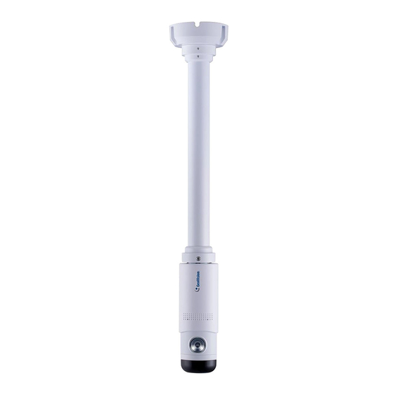
Page 15: Installing The Camera
Introduction 1.4 Installing the Camera The camera is designed for outdoors. With the standard package, you can install the camera on the ceiling. Adjoin the base with the straight tube by turning it clockwise. Figure 1-2 Thread the cables of the camera to the base end through the opposite end of the straight tube and rotate the straight tube clockwise to attach it to the camera. - Page 16 Connect a network cable to the camera. Optionally waterproof the network cable by disassembling the cap of the network connector and thread the network cable as illustrated below. Figure 1-5 Rotate the camera to adjust for the desired angle and tighten the screws to fixate its position.
-
Page 17: Chapter 2 Getting Started
Chapter 2 Getting Started 2.1 Looking Up the IP Address By default, GV-VR360 is assigned with a dynamic IP address when the camera is connected to a network with DHCP server. This IP address remains unchanged unless you unplug or disconnect your camera from the network. -
Page 18: Assigning An Ip Address
2.1.1 Assigning an IP Address When the DHCP server on your network is unavailable or disabled, the camera can be accessed by the default IP 192.168.0.10. To modify the static IP address, log on to the Web interface and access the network setting page. Open your Web browser and type the default IP address http://192.168.0.10. -
Page 19: Accessing The Live View
Getting Started 2.2 Accessing the Live View Two types of users are allowed to log on to the GV-VR360: Administrator and Guest. The Administrator has full access to all system configurations of the camera, while the Guest can only access its live view and network status. -
Page 20: The Live View Window
2.2.1 The Live View Window Figure 2-4 No. Name Function Play Plays live video. Stop Stops playing video. Snapshot Takes a snapshot of the live video. Full Screen Switches to full screen view. File Save Records live video to the local computer. Access and configure the following image settings: Video Attribute, Orientation, Flickerless, D/N, D/N Sensitivity, White Control Panel... -
Page 21: The Control Panel Of The Live View Window
Getting Started 2.2.2 The Control Panel of the Live View Window Using the control panel on the right side of the Live View window, you can adjust the following image settings. Note these settings are only accessible by the Administrator. Figure 2-5 [Image] Video Attributes: Adjusts the Brightness, Saturation, Contrast and Sharpness of the live... -
Page 22: Picture-In-Picture View
WDR (Wide Dynamic Range): Adjusts for clear images when the scene contains very bright and very dark areas at the same time. Select Strong to bring out details of the dark areas of the scene or Normal for a balanced effect. Defog: Select Auto to automatically enhance the visibility of images. -
Page 23: Chapter 3 Administrator Mode
Chapter 3 Administrator Mode The Administrator can access and configure the GV-VR360 over the network. Click System Settings at the top of the Web interface to access the following four configuration tabs: Audio & Video Settings, Events and Alerts, Network and Management. -
Page 24: Audio & Video Settings
3.1 Audio & Video Settings The GV-VR360 supports two streams, Streaming 1 and Streaming 2, which allow separate codec and resolution settings through a single video transmission. In a bandwidth-limited network, such as mobile phone surveillance, this dual-stream feature allows you to view live video in a lower resolution and codec (Streaming 2) while recording in a higher resolution and codec (Streaming 1). - Page 25 Administrator Mode [Video Format] Select either H.265 or H.264 as the codec type. Note: H.265 video codec is not supported for YouTube streaming. [Resolution] Select the desired resolution for video streaming from the drop-down list. The resolution of Streaming 2 will always be the same as Streaming 1. [Frame per Second] Select the desired FPS for video streaming from the drop-down list.
-
Page 26: Audio Settings
3.1.2 Audio Settings You can enable the microphone and select the audio quality from Low , Normal or YouTube. Select Built-in Microphone or External Microphone as the source of audio input. Figure 3-3 Note: 1. Normal audio quality and audio for YouTube streaming require AAC audio codec (optional) 2. -
Page 27: Metering
Administrator Mode 3.1.3 Metering Select between Center-Weighted Metering Mode and Evaluative Metering Mode for the camera to automatically measure the intensity of light. For Evaluative Metering Mode, click on a desired location on the image. Figure 3-4... -
Page 28: Rtsp
[Max Connection] Set the maximum number of RTSP connections to the camera, from 1 ~ 8. Note: 1. When the GV-VR360 is connected to a video management software and/or app, changing its RTSP settings may result in temporary disconnection or image freeze, for about 40 ~ 60 seconds 2. -
Page 29: Events And Alerts
Administrator Mode 3.2 Events and Alerts The Administrator can set up triggered actions, of either sending a snapshot by e-mail and/or activate an output device upon input events. For the abovementioned triggered actions, you must also configure the following settings: ... -
Page 30: Output Settings
3.2.1.2 Output Settings Select Enable to activate the output device. Figure 3-7 Name: Type a desired name for the output. Normal State: Select the output signal that best suits your device between Open Circuit (N/O) / Grounded Circuit (N/C). ... -
Page 31: E-Mail
Administrator Mode 3.2.2 E-mail You can set up e-mail address(es) for receiving e-mail notifications upon input triggers. Note: To send e-mail alerts upon input events, be sure to configure the input settings. See 3.2.1.1 Input Settings. Figure 3-8 To configure the e-mail settings: 1. -
Page 32: Network
3.3 Network The Network settings includes some basic but important network configurations that enable the GV-VR360 to be connected to a TCP/IP network. 3.3.1 LAN Configuration Select between Static IP address and Dynamic IP address according to your network environment. -
Page 33: Advanced Tcp/Ip
DDNS (Dynamic Domain Name System) provides a convenient way of accessing the camera when using a dynamic IP. DDNS assigns a domain name to the GV-VR360 for connection without the need of checking if the IP address assigned by DHCP Server or ISP (in xDSL... - Page 34 DDNS V2 and obtain a host name. Figure 3-12 3. Type the Host Name used to link to the GV-VR360. For users of GeoVision DDNS Server, the system will detect for the host name automatically. 4. Type the User Name and Password used to enable the service from the DDNS server.
-
Page 35: Ip Filter
Administrator Mode [HTTP] The HTTP port enables the GV-VR360 to be connected to the Web. For security purposes, the Administrator can hide the server from the general HTTP by changing the default port 80 to a different value within the range of 1025 ~ 65535. -
Page 36: Management
You can also view the firmware version and execute certain system operations. 3.4.1 Date and Time The date and time settings are used to set the time of the GV-VR360. Figure 3-14 [Date & Time on IP Camera] Displays the current date and time of the camera. -
Page 37: User Account
Administrator Mode [Synchronized with your computer or modify manually] Manually changes the camera’s date and time or select Synchronized with your computer to synchronize the camera’s date and time with those of the local PC. 3.4.2 User Account You can change the login name and password of the Administrator and Guest accounts. ... -
Page 38: Tools
Web interface. Figure 3-16 [Device Settings] You can reboot the GV-VR360, restore it back to its factory default settings or import / export the system settings. Reboot: Click Reboot for the camera to restart. -
Page 39: System Log
Administrator Mode 3.4.4 System Log The system log contains dump data required for problem diagnosis by service personnel. Clear: Click Clear to delete all system logs. Download: Click Download to download all system logs to the local computer. ... -
Page 40: Chapter 4 Youtube Live Stream
Chapter 4 YouTube Live Stream GV-VR360 can be streamed online, through YouTube, for a 360° live VR video that can be viewed by the user and/or viewers with granted access. Figure 4-1 To set up the live stream of GV-VR360 over YouTube, refer to the related settings below: Step 1 Obtaining Stream Name &... -
Page 41: Setting Youtube Live Stream
YouTube Live Stream 4.1 Setting YouTube Live Stream Before setting up a live stream, you need to have a YouTube account and complete the required settings to obtain the stream name and RTMP server URL. To do so, log in to your YouTube account and follow the steps below. - Page 42 Name the live stream. Set the start time of your live stream and Add end time if necessary. In the upper-right drop-down list, select between Unlisted and Public, for the stream to be viewable only by you or open to the public. Select Custom under Type.
-
Page 43: Configuring Live Stream Settings
YouTube Live Stream 4.2 Configuring Live Stream Settings Once your YouTube live stream event is set, go to the camera’s Web interface, click System Settings, Audio & Video Settings and select Live to configure its live stream settings. Figure 4-8 ... -
Page 44: Starting Live Stream
4.3 Starting Live Stream After the required settings are set, go back to the YouTube website and select Live control room. Click Preview and click Start Streaming. Figure 4-9 The live video stream of GV-VR360 is now viewable on YouTube. -
Page 45: Chapter 5 Smart Device Connection
Chapter 5 Smart Device Connection You can access the live video stream of GV-VR360 and view it in VR mode through mobile devices using the mobile application GV-Eye. YouTube mobile app is also supported. Download GV-Eye from Google Play or Apple Store. -
Page 46: Chapter 6 Advanced Applications
Chapter 6 Advanced Applications This chapter introduces advanced applications. 6.1 Upgrading System Firmware GeoVision periodically updates the latest firmware to the company website. You can update the camera’s firmware through the Web interface or GV-IP Device Utility. 6.1.1 Using the Web Interface 1. -
Page 47: Using The Gv-Ip Device Utility
Advanced Applications 6.1.2 Using the GV-IP Device Utility The IP Device Utility provides another way to upgrade the firmware. Note the computer used to upgrade firmware must be under the same network as the camera. 1. Download and install the GV-IP Device Utility from our website. 2. - Page 48 5. Click the Firmware Upgrade tab. This dialog box appears. Figure 6-4 5. Click the Browse button to locate the firmware file (.zip) saved at your local computer. 6. Type the Password and click Upgrade to start updating.
-
Page 49: Restoring To Factory Default Settings
Advanced Applications 6.2 Restoring to Factory Default Settings If for any reason the camera is not responding correctly, you can reset it to its factory default setting by using the camera’s Web interface or by operating directly on the camera. 6.2.1 Using the Web Interface On the Web interface, go to System Settings. - Page 50 Press and hold the Default button on the camera body. This shall take about 5 seconds. Release the Default button. The camera reboots automatically once the process of loading default settings is completed.
-
Page 51: Chapter 7 Vms Configurations
When a GV-VR360 is connected to IE browser or GeoVision CMS applications, it takes up 1 stream; when it is connected to GV-VMS, it takes up 1 to 2 streams. Note: By default, GV-VR360 is in single stream and will take up 1 stream when connected to GV-VMS. -
Page 52: Setting Up Ip Cameras On Gv-Vms
7.1 Setting Up IP Cameras on GV-VMS Follow the steps and conform the integration specification below to manually connect your GV-VR360 to GV-VMS. Note: The following instructions are based on V17.1 software and user interfaces. To access the IP Device Setup page, click Home... - Page 53 VMS Configurations Double-click GV-VR360 and type the User name and Password of the camera. Figure 7-3 Click OK and this dialog box appears. Figure 7-4...
- Page 54 Click OK to add the camera to the list. To connect the added camera, click the box besides the ID column. Upon successful connection, the Status icon shows green, with the video resolution and bit rate being displayed in the correspondent columns. Figure 7-5...
-
Page 55: Appendix
Appendix A. RTSP Protocol Support The GV-VR360 supports RTSP protocol for both video and audio streaming. For RTSP command, enter: rtsp://<IP of the GV-VR360:8554/<CH No.>.sdp For example, rtsp://192.168.3.111:8554/CH001.sdp If RTSP authentication is used, enter: rtsp://<username>:<password>@<IP of the GV-VR360>:<RTSP port>/<CH No.>.sdp For example, rtsp://admin.admin@192.168.0.200:8554/CH001.sdp...
Need help?
Do you have a question about the GV-VR360 and is the answer not in the manual?
Questions and answers