Table of Contents
Advertisement
Quick Links
Advertisement
Table of Contents

Related Manuals for AXIOMTEK DK1211C


Summary of Contents for AXIOMTEK DK1211C
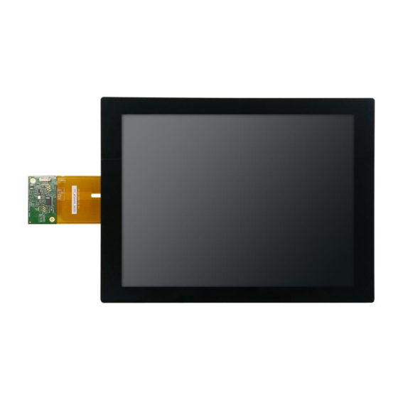
- Page 1 DK1211C User Guide DK1211C 12.1" Industrial Display Module Kit User Guide...
-
Page 2: Disclaimers
Axiomtek does not make any commitment to update the information in this manual. Axiomtek reserves the right to change or revise this document and/or product at any time without notice. No part of this document may be reproduced, stored in a retrieval system, or transmitted, in any form or by any means, electronic, mechanical, photocopying, recording, or otherwise, without the prior written permission of Axiomtek Co., Ltd. -
Page 3: Safety Precautions
Disconnect the power cords before making any installation. Be sure both the system and the external devices are turned OFF. Sudden surge of power could ruin sensitive components. Trademarks Acknowledgments Axiomtek is a trademark of Axiomtek Co., Ltd. ® Windows is a trademark of Microsoft Corporation. -
Page 4: Table Of Contents
DK1211C User Guide Table of Contents Disclaimers ......................2 Safety Precautions ....................3 Chapter 1 Introduction ..............5 1.1 General Description ..................5 1.2 Display Characteristics .................6 1.3 Absolute Maximum Ratings .................6 1.4 Block Diagram ....................8 1.5 Mechanical Dimensions ................9 Chapter 2 Electrical Characteristics ..........12 2.1 TFT LCD Module .................. -
Page 5: Chapter 1 Introduction
Introduction General Description The DK1211C is a 12.1” TFT-LCD module with a white LED Backlight Unit and 1ch-LVDS interface. This module supports 800 x 600 SVGA MVA mode and displays 262K/ 16.2M colors and adopt projected capacitive touch. The converter for the LED Backlight Unit is built in. -
Page 6: Display Characteristics
DK1211C User Guide Display Characteristics Item Specifications Unit Active Area 246.00 (W) x 184.50 (H) Outline Dimension 260.50(W) × 204.00(H) × 8.40(D) Pixels H x V 800 x 600 Pixel Pitch 0.3075× 0.3075 Display Colors 262K / 16.2M color White Luminance... -
Page 7: Electrical Absolute Ratings
DK1211C User Guide Note (4): No condensation. 1.3.2 Electrical Absolute Ratings 1.3.2.1 TFT LCD MODULE Item Symbol Min. Max. Unit Remark Power Supply Voltage -0.3 1.3.2.2 LED CONVERTER Item Symbol Min. Max. Unit Remark Converter Voltage -0.3 (1)(2) Enable Voltage Backlight Adjust Note (1): Permanent damage to the device may occur if maximum values are exceeded. -
Page 8: Block Diagram
DK1211C User Guide Block Diagram... -
Page 9: Mechanical Dimensions
DK1211C User Guide Mechanical Dimensions 1.5.1 Outline Drawing (Front Side) - Page 10 DK1211C User Guide 1.5.2 Outline Drawing (Back Side)
- Page 11 DK1211C User Guide This page is intentionally left blank...
-
Page 12: Chapter 2 Electrical Characteristics
DK1211C User Guide Chapter 2 Electrical Characteristics TFT LCD Module Ta = 25 ± 2 ºC Item Symbol Min. Typ. Max. Unit Condition at VCC=3.3V Power Supply Voltage 4.75 5.25 at VCC=5.0V Rush Current IRUSH (2), at VCC=5.0V (3) a, at VCC=3.3V,... - Page 13 DK1211C User Guide Note (1) The module is recommended to operate within specification ranges listed above for normal function. Note (2) Measurement Conditions: Note (3) The specified power supply current is under the conditions at Ta = 25 ± 2 ºC, fv = 60...
-
Page 14: Led Converter
DK1211C User Guide LED CONVERTER Ta = 25 ± 2 ºC Item Symbol Min. Typ. Max. Unit Condition Converter Power Supply 10.8 12.0 13.2 (Duty 100%) Voltage Converter Power Supply @ Vi = 12V 0.53 Current (Duty 100%) Converter Power... -
Page 15: The Input Data Format
DK1211C User Guide The Input Data Format... -
Page 16: Optical Characteristics
DK1211C User Guide Optical Characteristics Item Symbol Conditions Min. Typ. Max. Unit Note 0.600 0.353 0.348 Green 0.568 Color Typ - Typ + (1)(5) Chromaticity 0.05 0.05 0.150 θ =0°, θ =0° Blue CS-2000 0.097 0.313 White 0.329 Center Luminance of White... - Page 17 DK1211C User Guide Note (1) Definition of viewing angle: Note (2) Definition of Contrast Ratio, CR: The following expression can calculate the contrast ratio. Contrast Ratio, CR = L63 (255) / L0 L63: Luminance of gray level 63 (255)
- Page 18 DK1211C User Guide Note (4) Definition of Luminance of White, LC: Measure the luminance of gray level 63 (255) at center point LC = L (5) L (x) is corresponding to the luminance of the point X at Figure in Note (6).
-
Page 19: Interface Timing
DK1211C User Guide Interface Timing Item Signal Symbol Min. Typ. Max. Unit Note Total Tv=Tvd+Tvb Vertical Display Active Display Term Blank Tv-Tvd Tv-Tvd Total 1056 1150 Th=Thd+Th Horizontal Active Display Display Term Blank Th-Thd Th-Thd Frequency DCLK 48.3 Note (1): Because this module is operated by DE only mode, Hsync and Vsync input signals should be set to low logic level or ground. -
Page 20: Power On/Off Sequence
DK1211C User Guide Power On/Off Sequence To prevent a latch-up or DC operation of LCD module, the power on/off sequence should follow the conditions shown in the following diagram. Note (1) Please avoid floating state of interface signal at invalid period. -
Page 21: Chapter 3 Input Terminal Pin Assignments
DK1211C User Guide Chapter 3 Input Terminal Pin Assignments TFT LCD Module Interface Pin # Symbol Description Remark RX3+ Differential Data Input, CH3 (Positive) RX3- Differential Data Input, CH3 (Negative ) SEL68 LVDS 6/8 bit select function control, Note ( 3 ) Low or NC ->... - Page 22 DK1211C User Guide Note (1) Connector Part No.: FI-SEB20P-HFE(JAE) or 076B20-0048RA-G4(STARCONN) or equivalent. Note (2) User’s connector Part No.: FI-SE20ME(JAE) or equivalent Note (3) “Low” stands for 0V. “High” stands for 3.3V. “NC” stands for “No Connected”.
-
Page 23: Backlight Unit
DK1211C User Guide Backlight Unit Pin # Symbol Description Remark Converter input voltage Converter input voltage Converter input voltage Converter input voltage VGND Converter ground Ground VGND Converter ground Ground VGND Converter ground Ground VGND Converter ground Ground Enable pin 3.3V... - Page 24 DK1211C User Guide This page is intentionally left blank...
-
Page 25: Chapter 4 Touch Screen
DK1211C User Guide Chapter 4 Touch Screen Touch Characteristics 4.1.1 General Specifications Item Specifications Unit Touch Technology Projected capacitive touch Touch Panel Size 12.1 inch Touch Tail Design View Area 247.00(W) x 185.50(H) Total Thickness 1.59±0.30 Outline Dimension 290.00(W) x 220.50(H) x 1.59(D) -
Page 26: Electrical Characteristics
DK1211C User Guide Electrical Characteristics (Ta=25±2°C) Value Item Symbol Unit Note Min. Typ. Max. Power Supply Voltage Response time Power Consumption @5.0V Report Rate... -
Page 27: Touch Pin Assignment
DK1211C User Guide Touch Pin Assignment Pin No. Symbol GND_EARTH Front View... - Page 28 DK1211C User Guide This page is intentionally left blank...
-
Page 29: Appendix A Hanling Precaution
DK1211C User Guide Appendix A Handling Precautions A1 Handling Precautions (1) Do not apply rough force such as bending or twisting to the module during assembly. (2) To assemble or install module into user’s system can be only in clean working areas. The dust and oil may cause electrical short or worsen the polarizer. - Page 30 DK1211C User Guide This page is intentionally left blank...
Need help?
Do you have a question about the DK1211C and is the answer not in the manual?
Questions and answers