
Subscribe to Our Youtube Channel
Related Manuals for BK Precision 1651A


Summary of Contents for BK Precision 1651A
-
Page 1: Dc Power Supply
INSTRUCTION MANUAL MODELS 1651A & 1652 MODELOS 1651A & 1652 El Manual de la Instrucción Triple Output DC POWER SUPPLY FUENTES DE PODER De Triple Salida DC... -
Page 2: Test Instrument Safety
Observe the following safety precautions: 1. There is little danger of electrical shock from the dc output of this power supply. However, there are several other possible test conditions using this power supply that can create a high voltage shock hazard: a. -
Page 3: Dc Power Supply
Instruction Manual Triple Output DC POWER SUPPLY 22820 Savi Ranch Parkway Yorba Linda, CA 92887 www.bkprecision.com... -
Page 4: Table Of Contents
Independent Use of “A” or “B” Supply ...12 Series Tracking Operation...18 TABLE OF CONTENTS Page Parallel Tracking Operation... 22 Fixed 5 V Power Supply Operation... 25 APPLICATIONS... 29 General ... 29 Electronics Servicing... 29 Electronics Manufacturing... 29 Electronics Design Lab... 30 Electronics Education ... -
Page 5: Introduction
The B & K-Precision Models 1651A & 1652 Triple Output DC Power Supplies are high quality, general purpose dc power sources. They provide two supplies with a 0-24 volt dc output and one with a fixed 5 volt dc output. The 0-24V supplies are adjustable and are capable of current output of 0-0.5 amp. - Page 6 Their laboratory quality specifications will meet most engineering laboratory requirements. The same features that make the Model 1651A and 1652 a good choice for an engineering lab also make them a good choice engineering for most other solid state electronic applications.
-
Page 7: Features
TRIPLE OUTPUT Operates as three separate power supplies. Each has floating output and is completely isolated from the other two. ONE FIXED 5V SUPPLY 0-to-4 amp fixed 5 volt supply is ideal for use with most digital logic circuitry. Adequate current capacity for extensive circuitry. -
Page 8: Isolated Output
OVERLOAD PROTECTION Fully adjustable current limiting (from 6% to 100% of maximum output current) for “A” and “B” supplies protects circuit under test and the power supply REVERSE POLARITY PROTECTION Prevents damage to power supply from external voltage of reverse polarity. -
Page 9: Specifications
“A” AND “B” SUPPLIES Output Voltage Range: 0V to 24VDC (0 ± 100mV) Output Current Limit Range: 0 to 0.5A. Constant Voltage Operation: Voltage Regulation: Load: ≤0.01% + 3mV Line (108 – 132V): ≤0.01% + 3mV Ripple Noise: ≤2mVrms (5Hz to 1MHz) Recovery Time: ≤100us typical. - Page 10 SPECIFICATIONS_____________________________________________________________________________________ FIXED 5V SUPPLY Output Voltage: Maximum Current: Load Regulation: Line Regulation 108 – 132 V: Ripple And Noise: Overvoltage Protection Threshold: GENERAL Power Requirements: Power Consumption: Protection: NOTE: Specifications and information are subject to change without notice. Please visit most current product information.
-
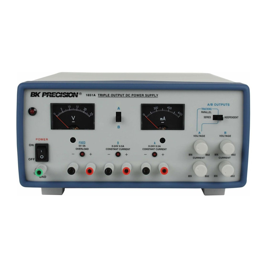
Page 11: Controls And Indicators
1. POWER Switch. Turns power on and off. 2. Power ON light. Red LED lights to indicate a power on condition. 3. GND Terminal (Green). Earth and Chassis Ground. 4. A/B Metering Switch. Selects simultaneous Voltage & Current metering for the “A” or “B” supplies. When in the A position, the V and mA meters are connected to the “A”... - Page 12 CONTROLS AND INDICATORS__________________________________________________________________________ Figure 1. Front panel controls and indicators...
-
Page 13: B" Supply Controls And Indicators
“B” supply. 13. CONSTANT CURRENT Indicator. Red LED lights when “A” supply is in the Constant Current mode. The Power Supply regulates the output current at the value set by the “A” CURRENT control. In the Parallel Tracking mode, when this indicator is lit, both the “A”... -
Page 14: Fixed 5V Supply Terminals And Indicator
CONTROLS AND INDICATORS__________________________________________________________________________ FIXED 5V SUPPLY TERMINALS AND INDICATOR 19. “+” Terminal (Red). Positive polarity output terminal for FIXED 5V supply. 20. “-“ Terminal (Black). Negative polarity output terminal for FIXED 5V supply. 21. OVERLOAD Indicator. Lights when load on FIXED 5 Volt supply becomes too large. - Page 15 __________________________________________________________________________CONTROLS AND INDICATORS Figure 2. Rear panel controls.
-
Page 16: Operating Instructions
Avoid using the power supply in ambient temperatures above +40° C. Always allow sufficient air space around the heat sink at the rear of the power supply for effective radiation to prevent internal heat build-up. Although the power supply is protected against reverse polarity damage, the circuit being powered may not include such protection. - Page 17 ___________________________________________________________________________OPERATING INSTRUCTIONS Hook-up 3. Set the INDEPENDENT/TRACKING mode switch to the right position so that the power supply is in the INDEPendent operating mode. 4. Set the A/B Metering selection switch to the A (up) position to monitor the “A” supply.
- Page 18 OPERATING INSTRUCTIONS___________________________________________________________________________ Figure 3. Independent operation grounding possibilities (sheet 1 of 2)
- Page 19 ___________________________________________________________________________OPERATING INSTRUCTIONS Figure 3. Independent operation grounding possibilities (sheet 2 of 2)
- Page 20 3. Set CURRENT control counterclockwise). Figure 4. Typical constant voltage operation 4. Turn off the power supply and connect it to the device to be powered. 5. Turn on the power supply. The CONSTANT CURRENT minimum (fully indicator should light.
- Page 21 8. If the load current drops below the constant current value, the CONSTANT CURRENT indicator will go off. In this case, the power supply automatically switches to the constant voltage mode, and further rotation of the CURRENT control will not increase the output current.
-
Page 22: Series Tracking Operation
Fig. 7 shows the relationship between this crossover point and the load. For example, if the load is such that the power supply is operating in the constant voltage mode, a regulated output voltage is provided. - Page 23 __________________________________________________________________________OPERATING INSTRUCTIONS Figure 8. Series tracking (0-48 V) operation grounding possibilities (sheet 1 of 3).
- Page 24 OPERATING INSTRUCTIONS___________________________________________________________________________ Figure 8. Series tracking (0-48 V) operation grounding possibilities (sheet 2 of 3)
- Page 25 VOLTAGE control (remember that the actual output voltage is double the reading on the Volt meter). 5. Turn off the power supply and the equipment to be powered during hook-up. 6. Connect the positive polarity of the device being powered to the red (+) terminal of the “A”...
-
Page 26: Parallel Tracking Operation
4. Adjust the output voltage to the desired level using the “A” VOLTAGE control. 5. Turn off the power supply and the equipment to be powered during hook-up. 6. Connect the positive polarity of the device being powered to the red (+) terminal of the “A”... - Page 27 __________________________________________________________________________OPERATING INSTRUCTIONS Figure 9. Parallel tracking operation grounding possibilities (sheet 1 of 2).
- Page 28 OPERATING INSTRUCTIONS___________________________________________________________________________ Figure 9. Parallel tracking operation grounding possibilities (sheet 2 of 2).
-
Page 29: Fixed 5 V Power Supply Operation
The FIXED 5 V supply provides a 4 amp current capacity. The supply is ideal for use with TTL circuits. 1. Turn off the power supply and the equipment to be powered during hook-up. 2. Connect the positive polarity of the device being powered to the red (+) terminal of the FIXED 5 V supply. - Page 30 OPERATING INSTRUCTIONS___________________________________________________________________________ Figure 10. Grounding possibilities for fixed 5 V power supply (sheet 1 of 2).
- Page 31 __________________________________________________________________________OPERATING INSTRUCTIONS Figure 10. Grounding possibilities for fixed 5 V power supply (sheet 2 of 2).
- Page 32 The hook-up leads supplied with the power supply are rated for 4 amps. 7. If the red OVERLOAD indicator lights, too much load has been placed on the supply. This will cause voltage and current to drop and prevent proper operation of the FIXED 5 V supply.
-
Page 33: Applications
GENERAL The Model 1651A power supply has a very wide variety of applications in electrical and electronics servicing, engineering laboratories, manufacturing and testing facilities, schools, and home hobbying. The “A” and “B” power supply outputs are fully adjustable from 0-to-24 volts and 0-to-0.5 amps and the FIXED 5 V supply has a current capability of 0-to-4 amps. -
Page 34: Electronics Design Lab
SPLIT SUPPLY Frequently, “split power supplies” are required for amplifiers and other electronic circuits. The Model 1651A is ideally suited for “split power supply” operation. This supply can be configured to provide two positive voltages with a... - Page 35 3. Connect a ground wire between the “A” supply’s negative terminal and the GND (green) terminal. 4. Turn off the power supply and the equipment to be powered during hook-up. 5. Connect the positive polarity inputs of the circuit to be...
- Page 36 5. Connect the ground straps between each supplies’ negative terminal and the GND (green) terminal. 6. Turn off the power supply and the equipment to be powered during hook-up. 7. Connect the positive polarity inputs of the circuit to be powered to the positive (red) terminal of the supply.
- Page 37 3. Connect a ground wire between the “A” supply positive terminal and the GND (green) terminal. 4. Turn off the power supply and the equipment to be powered during hook-up. 5. Connect the negative polarity inputs of the circuit to be powered to the negative (black) terminals of the supplies.
- Page 38 5. Connect the ground wires between each supplies’ positive terminal and GND (green) terminal. 6. Turn off the power supply and the equipment to be powered during hook-up. 7. Connect the negative polarity inputs of the circuit to be powered to the negative (black) terminals of the supplies.
- Page 39 3. Connect a ground wire between the “A” supply negative terminal and the GND (green) terminal. 4. Turn off the power supply and the equipment to be powered during hook-up. 5. Connect the positive polarity input of the circuit to be powered to the positive (red) terminal of the “A”...
- Page 40 “B” supply and the GND (green) terminal. 6. Turn off the power supply and the equipment to be powered during hook-up. 7. Connect the positive polarity input of the circuit to be powered to the positive (red) terminal of the “A”...
-
Page 41: Maintenance
FUSE REPLACEMENT If the fuse blows, the LED indicator will not light and the power supply will not operate. The fuse should not normally open unless a problem has developed in the unit. Try to determine and correct the cause of the blown fuse, then replace only with a fuse of the correct rating. -
Page 42: Service Information
Service Information Warranty Service: Please return the product in the original packaging with proof of purchase to the address below. Clearly state in writing the performance problem and return any leads, probes, connectors and accessories that you are using with the device. Non-Warranty Service: Return the product in the original packaging to the address below. -
Page 43: Limited One-Year Warranty
Limited One-Year Warranty B&K Precision Corp. warrants to the original purchaser that its products and the component parts thereof, will be free from defects in workmanship and materials for a period of one year from date of purchase. B&K Precision Corp. will, without charge, repair or replace, at its option, defective product or component parts. Returned product must be accompanied by proof of the purchase date in the form of a sales receipt. - Page 44 “hot chassis”. To make measurements in “hot chassis” equipment, always connect an isolation transformer between the ac outlet and the equipment under test. The B+K Precision Model TR-110 or 1604 Isolation Transformer, or Model 1653 or 1655 AC Power Supply is suitable for most applications.
-
Page 45: Spanish Manual
MANUAL DE INSTRUCCIÓNES FUENTE DE PODER DE CD TRIPLE MODELOS 1651A & 1652 22820 Savi Ranch Parkway Yorba Linda, CA 92887 www.bkprecision.com... - Page 46 El uso normal de equipo de prueba lo expone a un posible riesgo de choque eléctrico debido a que las pruebas pueden realizarse cuando en presencia de alto voltaje expuesto. Un choque eléctrico que permita el paso de 10mA de corriente por el corazón causará que deje de latir. Voltajes tan bajos como 35 volts DC o AC RMS considerarse como de peligro dado que pueden causar corrientes letales bajo ciertas condiciones.
- Page 47 SEGURIDAD DEL INSTRUMENTO DE PRUEBA INTRODUCCION... 44 CARACTERISTICAS ... 45 ESPECIFICACIONES ... 47 CONTROLES E INDICADORES ... 49 De la fuente A ... 49 De la fuente B... 51 Terminales e indicador de la fuente fija de 5V... 52 Controles del panel trasero ... 52 INSTRUCCIONES DE OPERACIÓN ...
-
Page 48: Introduccion
Los modelos 1651A &1652 de BK Precision son fuentes de poder de salida triple de CD de propósito general y alta calidad. Incluyen 2 fuentes variables de 0-24 volts y una fija de 5V DC. Las fuentes variables son ajustables y proveen una salida de corriente de 0-0.5 amps. -
Page 49: Caracteristicas
SALIDA TRIPLE Opera como tres fuentes de poder separadas. Cada una tiene salida flotante y está totalmente aislada de las otras dos. FUENTE FIJA DE 5V Fuente fija de 0 a 5V ideal para la mayoría de los circuitos digitales. Capacidad de corriente adecuada para circuitos extensos. - Page 50 CARACTERÍSTICAS SALIDA AISLADA Cualquier polaridad puede flotarse o conectarse a tierra PROTECCIÓN CONTRA SOBREFLUJO La limitación de corriente totalmente ajustable (de 6% a 100% de la corriente máxima de salida) para las fuentes “A” y “B” protege tanto a la fuente de poder como al circuito bajo prueba. PROTECCIÓN DE POLARIDAD INVERSA CABLES Se entregan 3 juegos de cables de conexión...
-
Page 51: Especificaciones
FUENTES “A” Y “B” Rango del voltaje de salida: 0V a 24V (0+- 100mV) Rango de Corriente limitada de salida: 0 a 0.5A Operación de voltaje constante: Regulación de voltaje: Carga: Línea (108-132V): Ruido de ondulaccion: Tiempo de recuperación: Coeficiente de temperatura 0°C a 40°C Error de rastreo Sin carga:... - Page 52 ESPECIFICACIONES FUENTE FIJA DE 5V Corriente máxima: ≥4A Regulación de carga: ≥ 10mV Regulación de línea 108-132V: ≤5mV Ondulaccion y ruido ≤2mV rms (5Hz a 1Mhz) Umbral de protección de sobrevoltaje: 5.7 a 6.5V GENERAL Requerimientos de potencia: 100/120/220/240VAC ±10%, 50/60Hz Consumo de Potencia: 165VA Protección:...
-
Page 53: Controles E Indicadores
Interruptor de encendido POWER. Enciende o apaga al equipo Lámpara de encendido. El Led rojo prende al encenderse la unidad Terminal GND (verde). Tierra física y de chasis Interruptor medidores simultáneamente la medición de voltaje&corriente de las fuentes A y B. En la posición A, los medidores V y mA se conectan a la fuente A, mientras que se conectan a la fuente B en la posición B. - Page 54 Figura 1. Controles e indicadores del panel frontal...
-
Page 55: De La Fuente A
CONTROLES E INDICADORES 10. Control CURRENT. Ajusta la corriente límite de A en modo de voltaje constante. Ajusta la corriente constante de A en modo de corriente constante. Ajusta el valor de corriente constante de B en modo de rastro serial o paralelo. La corriente se lee en el medidor mA al seleccionar el modo A. -
Page 56: Terminales E Indicador De La Fuente Fija De 5V
CONTROLES E INDICADORES INDICADORES Y CONTROLES DE LA FUENTE DE 5V 25. Terminal “+“ (roja). Terminal de polaridad positiva de la fuente FIXED de 5V. 26. Terminal “-“ (negra). Terminal de polaridad negativa de la fuente FIXED de 5V. 27. Indicador de sobreflujo OVERLOAD de 5A. Enciende cuando la carga de la fuente es excesiva. - Page 57 Figura 2. Controles del panel trasero...
-
Page 58: Instrucciones De Operación
PRECAUCIONES PARA SEGURIDAD PRECAUCION Evite tocar el disipador de calor en la parte trasera de la fuente de poder. Cuando la fuente provee una corriente alta en cualquiera de sus salidas el disipador puede estar muy caliente. El tocarlo en estas condiciones puede ocasionar quemadas de la piel o daños al equipo que esté... -
Page 59: Conexiones
INSTRUCCIONES DE OPERACIÓN Conexiones Ajuste el interruptor INDEP/TRACK a su posición de la derecha para que la fuente opere en modo INDEP. Seleccione la posición superior del interruptor A/B de los medidores para monitorear a la fuente A. Apague la fuente de poder y el circuito bajo prueba durante el proceso de conexión Conecte la terminal positiva del equipo bajo prueba a la terminal roja (+) de la fuente... - Page 60 Figura 3. Posibilidades de conexión a tierra en operación independiente (1 de 2)
- Page 61 Figura 3. Posibilidades de conexión a tierra en operación independiente (2 de 2)
-
Page 62: Estableciendo La Corriente Límite
INSTRUCCIONES DE OPERACIÓN Si la corriente de carga excede del límite preestablecido, el indicador CONSTANT CURRENT se encenderá. En este caso, la fuente entra automáticamente en modo de corriente constante y no es posible aumentar el voltaje aunque rote aún más el control VOLTAGE. Estableciendo la corriente límite Determine la máxima corriente soportada con seguridad por el dispositivo por probar... - Page 63 INSTRUCCIONES DE OPERACIÓN Fig. 5. Estableciendo la corriente límite Incremente la corriente mediante CURRENT hasta que el valor deseado aparezca en el medidor, o establezca de antemano la corriente límite (antes de conectar la carga) como se describe en el procedimiento “Estableciendo la corriente límite”...
-
Page 64: Voltaje Constante/Corriente Constante
INSTRUCCIONES DE OPERACIÓN Característica de voltaje constante/corriente constante La característica de trabajo de la fuente es del tipo de cruce automático de voltaje/corriente. Esto permite la transición continua de los modos de corriente constante a voltaje constante en respuesta a cambios de la carga. La intersección de los modos de corriente y voltaje constantes se llama el punto de cruce. - Page 65 Fig. 8. Posibilidades de conexión a tierra en la operación de rastreo en serie (0-48V) (1 de 3)
- Page 66 Fig. 8. Posibilidades de conexión a tierra en la operación de rastreo en serie (0-48V) (2 de 3)
- Page 67 INSTRUCCIONES DE OPERACIÓN En este modo, el voltaje máximo de salida de ambas fuentes “A” y “B” puede variarse simultáneamente con un control. El voltaje máximo de “B” puede fijarse al mismo valor de la fuente “A” mediante el control VOLTAGE de A. El voltaje total a través de ambas fuentes es de hecho el doble de la lectura del medidor.
-
Page 68: Operación De Rastreo Paralelo
INSTRUCCIONES DE OPERACIÓN Similarmente, polaridad aterrizarse uniendo la terminal roja (+) de “A” a la verde (GND) de “A” como en la Fig. 8B. Si desea una operación de “fuentes separadas” puede lograr un voltaje positivo y uno negativo con tierra central uniendo las terminales negra (-) y verde (GND) de la fuente “A”... - Page 69 Fig. 9. Posibilidades de conexión a tierra en operación de rastreo en paralelo (1 de 2)
- Page 70 Fig. 9. Posibilidades de conexión a tierra en operación de rastreo en paralelo (2 de 2)
-
Page 71: Operación De La Fuente Fija De 5V
INSTRUCCIONES DE OPERACIÓN Si la polaridad negativa del circuito bajo prueba es también el chasis o común, puede conectarse a tierra uniendo la terminal (-) negra de “A” con la verde (GND) de “A” como se muestra en la Fig. 9A Similarmente, la polaridad positiva puede aterrizarse uniendo la terminal roja (+) de “A”... - Page 72 Fig. 10. Posibilidades de conexión a tierra para la fuente fija de 5V (1 de 2)
- Page 73 Fig. 10. Posibilidades de conexión a tierra para la fuente fija de 5V (2 de 2)
- Page 74 INSTRUCCIONES DE OPERACIÓN Asegúrese que los cables de conexión permiten la corriente suficiente y poseen resistencia baja entre la fuente y el circuito por probar. Los cables suministrados soportan 4A. Si enciende la luz roja indicadora de sobrecarga OVERLOAD significa que la carga es excesiva. Esto causa que bajen el voltaje y la corriente y evita que opere correctamente la fuente fija de 5V.
-
Page 75: Aplicaciones
GENERAL La fuente de poder modelo 1651A tiene una gran variedad de aplicaciones en servicio eléctrico y electrónico, laboratorios de ingeniería, instalaciones de manufactura y pruebas, escuelas y el hogar. Las salidas de las fuentes “A” y “B” son totalmente ajustables de 0 a 24 volts y 0 a 0.5 amps y la fuente de 5V ofrece una corriente... -
Page 76: Laboratorio De Diseño Electrónico
Con cierta frecuencia se requieren “fuentes de poder divididas” para amplificadores y otros circuitos electrónicos. El modelo 1651A es ideal para la operación de “fuente dividida”, con dos voltajes positivos y un negativo común, dos voltajes negativos y un positivo común, o bien uno negativo, uno positivo y una tierra común. - Page 77 APLICACIONES Dos voltajes positivos idénticos con un negativo común (Refiérase a la Fig. 9-11) Algunos equipos electrónicos requieren dos voltajes positivos idénticos con un negativo común. Un buen ejemplo es el de un reloj digital automotor con dos voltajes positivos de +12V y negativo común.
- Page 78 APLICACIONES Dos voltajes positivos diferentes con un negativo común (Refiérase a la Fig. 12) Muchos circuitos electrónicos requieren de dos voltajes positivos con un negativo común. Un ejemplo típico es el de un dispositivo que usa TTL (5V) y componentes analógicos (15V). Usando dos fuentes, la operación deseada se obtiene como sigue: Seleccione el modo independiente INDEP y el medidor para monitoreo de la fuente A...
- Page 79 APLICACIONES Dos voltajes negativos idénticos con un positivo común (Refiérase a la Fig. 13) Cuando se requiera el mismo voltaje negativo en dos puntos del mismo circuito y un positivo común, realice lo siguiente: 1. Seleccione el modo TRACKING PARALLEL y el medidor para monitoreo de la fuente A 2.
- Page 80 APLICACIONES Dos voltajes negativos diferentes con un positivo común (Refiérase a la Fig. 14) Usando ambas fuentes, se obtienen dos voltajes negativos diferentes con un positivo común como sigue: Seleccione el modo independiente INDEP y el medidor para monitoreo de la fuente A Fije el voltaje y corriente límite de A mediante los controles VOLTAGE y CURRENT de A Seleccione el medidor para monitoreo de la fuente B...
- Page 81 APLICACIONES Voltajes positivos y negativos idénticos con un común separado (refiérase a la Fig. 15) Otra aplicación típica de “fuente dividida” ocurre con amplificadores operacionales. Estos requieren típicamente voltajes positivo y negativo idénticos. Usando dos fuentes en modo de rastreo en serie se obtienen voltajes positivo y negativo idénticos con un común separado como sigue: Seleccione...
- Page 82 APLICACIONES Voltajes positivo y negativo diferentes con un común separado (Refiérase a la Fig. 16) Usando las dos fuentes en modo independiente, puede obtener voltajes positivos y negativos diferentes con un común separado como sigue: Seleccione el modo de operación INDEPENDENT y fije el medidor para monitorear voltaje de A Fije el voltaje y la corriente límite de A con los controles VOLTAGE y CURRENT de A...
-
Page 83: Mantenimiento
ADVERTENCIA Las instrucciones siguientes son para personal calificado solamente. Para evitar choque eléctrico, no realice ningún ningún servicio diferente a los incluidos en estas instrucciones de operación a menos que esté calificado para hacerlo. REEMPLAZO DE FUSIBLES Si el fusible se abre, el indicador LED no encenderá y la fuente no funcionará. -
Page 84: Información Sobre Servicio
Información de Servicio Servicio de Garantía: Por favor regrese el producto en el empaquetado original con prueba de la fecha de la compra a la dirección debajo. Indique claramente el problema en escritura, incluya todos los accesorios que se estan usado con el equipo. Servicio de No Garantía: Por favor regrese el producto en el empaquetado original con prueba de la fecha de la compra a la dirección debajo. -
Page 85: Garantia Limitada De Un Año
Garantía Limitada de Un Ano B&K Precision Corp. Autorizaciones al comprador original que su productos y componentes serán libre de defectos por el periodo de un ano desde el día en que se compro. B&K Precision Corp. sin carga, repararemos o sustituir, a nuestra opción, producto defectivo o componentes. Producto devuelto tiene que ser acompañado con prueba de la fecha del la compra en la forma de un recibo de las ventas. - Page 86 Párese sobre un material aislante en el piso, o tapete aislante, y coloque el equipo sobre una superficie aislante. Asegúrese que dichas superficies no estén húmedas o mojadas. Use la probada técnica de “una mano en el bolsillo” al manejar una punta de prueba. Evite particularmente el tocar algún objeto metálico cercano que pueda proveer una trayectoria a tierra.
- Page 87 Declares that the below mentioned product DC Power Supplies Product Name: 1651A, 1652, 1653A, 1655A, 1710A, 1711A, 1715A, 1730A, 1735A, 1740A, 1740B, 1743A, 1744, 1745, Part Numbers: 1745A, 1746A, 1760A, 1761 complies with the essential requirements of the following applicable European Directives: Low Voltage Directive 73/23/EEC (19.02.73) amended by 93/68/EEC (22.07.93)
- Page 88 22820 Savi Ranch Parkway Yorba Linda, CA 92887 www.bkprecision.com © 2005 B&K Precision Corp. 481-325-9-001 Printed in Taiwan...
Need help?
Do you have a question about the 1651A and is the answer not in the manual?
Questions and answers