Advertisement
Quick Links
Download this manual
See also:
Instruction Manual
Wireless, thermostatic TRV head
Manual for models: TRV10RFM, TRV10RAM i TRV28RFM
Quick Guide
DISTRIBUTOR OF SALUS CONTROLS:
QL CONTROLS Sp. z o.o., Sp. k.
Rolna 4,
43-262 Kobielice,
Poland
Importer:
SALUS Controls plc
Salus House, Dodworth Business Park
Whinby Road, Barnsley S75 3SP,
United Kingdom
www.salus-controls.eu
SALUS Controls is a member of the Computime Group
Maintaining a policy of continuous product development SALUS
Controls plc reserve the right to change specification, design and
materials of products listed in this brochure without prior notice.
Introduction
The TRV thermostatic head is controlled through wireless ZigBee
communication protocol. It can replace classic, manual thermostatic head in a
very quick and easy way. For proper operation of the TRV head it is necessary
to synchronize it correctly with wireless thermostat using the CO10RF
coordinator or UGE600 Internet gateway (all devices are sold separately). TRV
head paired with the iT600RF series digital thermostats (e.g. VS10RF / VS20RF
/ HTRS-RF (30) / HTRP-RF (50) / TS600) provides comfort within the whole
room, not just in the radiator area.
Product Compliance
This product complies with the essential requirements and other relevant
provisions of Directives 2014/53/EU, 2014/30/EU, 2011/65/EU. The full text
of the EU Declaration of Conformity is available at the following internet
address: www.saluslegal.com.
Safety Information
Use in accordance to national and EU regulations. Use the device as intended,
keeping it in dry condition. Product for indoor use only. Installation must be
carried out by a qualified person in accordance to national and EU regulations.
Box Content
TRV10RFM
TRV28RFM
TRV10RAM
TRV10RFM
adapter
TRV28RFM
metal
TRV10RAM
Allen Wrench key
washer
Each box additionally contains:
Manual
2 x AA batteries
instruction
General informations
The TRV head is a modulating device. This means that the valve can be
gradually closed or opened, depending on the current room temperature
measured by thermostat and the setpoint temperature.
+
+
OR
Note: One thermostat can control up to 6 TRV heads within one room.
To achieve the best possible results in cooperation between the thermostat
and the heating source, it is recommended to use the RX10RF receiver.
RX10RF turns on the heat source depending on the demand signal sent by
thermostat. More informations about RX10RF receiver is included in its user
manual.
Checking compatibility with the heating system
TRV head is compatible with most of the thermostatic valves available on
the market, however, before installation, please check whether the valve is
suitable for use with the TRV head.
1
radiator
valve
dismantle the old radiator
head
Note: If all valve dimensions are consistent with those given below, then the TRV
head will be compatible. If there are dimension differences, contact us or the installer
to find replacement for the valve.
2
3
Measure the thread diameter.
Measure the height of the valve's
Thread for the TRV10RFM must
pin when it is in the open position.
have a diameter of 30 mm, and for
For TRV10RFM valve's pin height
the TRV28RFM - 28 mm.
should be 13-15 mm, while for
TRV28RFM 10-11 mm.
TRV28RFM head installation
For MMA or Herz M28x1,5 thermostatic valves make
sure you have a metal washer as shown in the picture.
NOTE: For the Comap valve with M28 thread you do
not need to mount a metal washer.
TRV10RFM head installation
For a standard thermostatic valve with M30x1,5
thread (e.g. Oventrop, Honeywell, TA, Heimeier)
TRV10RFM head installation looks like as shown in
the picture.
TRV head installation on the Danfoss RA valve
When mounting the TRV10RFM head on the Danfoss
RA valve (see picture), please use the RA adapter
included with the head. However, to install the
TRV10RAM head it is necessary to use the Allen
Wrench key.
TRV10RFM HEAD MOUNTING
Tight RA
Put the RA
adapter
adapter on the
and screw
Danfoss RA
TRV10RFM
valve.
head on it.
TRV10RAM HEAD MOUNTING
Assembly to
the valve and
Place TRV
tighten only
head on the
2 out of 4
valve.
screws.
TRV head setup
1
2
Remove the battery cover located on
Insert the batteries according to the
the side of the device.
markings and close the battery cover.
3
4
When the LED diode lights up
The LED will start blinking
green
/
continuously with a
red
color,
red
informing about the software
screw the TRV on the valve.
version.
5
6
Press any button to start the
When the LED goes out and TRV
adaptation process of TRV head with
head does not make any sounds,
thermostatic valve. The process takes
adaptation process is finished.
up to 5 minutes.
Equipment is ready for pairing
with thermostat.
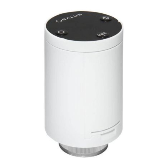
User interface
1
LED diode (indicates device status)
2
Opening the head / indication
of the device status
3
Closing the head / indication
vof the device status
4
Pairing button
Buttons function
Note: Buttons lock itself automatically after 5 minutes from the last one keystroke.
To do this...
Press the...
...pair with thermostat
...pairing button
for 10 seconds.
...pairing
and close
buttons together
...lock/unlock the buttons
for 5 seconds.
...manually open the valve
...opening button
for 5 seconds.
...manually close the valve
...closing button
for 5 seconds.
...enter the automatic mode
...shortly pairing button
...remove the head from the
...pairing button
for 10 seconds
ZigBee network
...Open
, pairing
, and close
...restore factory default settings
buttons together for 5 seconds
Advertisement

Subscribe to Our Youtube Channel
Related Manuals for Salus TRV10RFM


Summary of Contents for Salus TRV10RFM
- Page 1 (e.g. Oventrop, Honeywell, TA, Heimeier) QL CONTROLS Sp. z o.o., Sp. k. The TRV head is a modulating device. This means that the valve can be TRV10RFM head installation looks like as shown in LED diode (indicates device status) Rolna 4, the picture.
- Page 2 Connect equipment specification, for a period of two years from the date of installation. SALUS Controls sole liability for breach of this warranty will be (at its option) to repair or replace the defective product.
Need help?
Do you have a question about the TRV10RFM and is the answer not in the manual?
Questions and answers