
Related Manuals for Salus SC102ZB


Summary of Contents for Salus SC102ZB
- Page 1 Installation & Operation Manual SC102ZB Fan Coil Controller ST103 Wireless Fan Coil Remote SMC-IOM-SC102ZB-ST103ZB-2020.02v1_2020-02-10...
-
Page 2: Table Of Contents
SC102ZB/ST103ZB Installation and Operation Manual Contents Section Page Introduction Why SALUS? . . . . . . . . . . . . . . . . . . . . . . . . . . . . . . . . . . . . . . . . . . . . . . . . . . . . . . . . . . . . . . . . . . . . . . . . . . . . . . . . . . . . . . . . . . . . . 1-1 Using This Manual . - Page 3 SC102ZB/ST103ZB Installation and Operation Manual Contents Section Page Thermostat Configuration Settings Button Operation . . . . . . . . . . . . . . . . . . . . . . . . . . . . . . . . . . . . . . . . . . . . . . . . . . . . . . . . . . . . . . . . . . . . . . . . . . . . . . . 8-1 Special Function Codes .
-
Page 4: Introduction
Salus also offers a broad ecosystem of smart home products, including connected thermostats, a smart home hub, smart plugs, water valve shutoff, and door and window sensors . A proven leader in the European market since 2003, Salus is currently expanding across North America . Using this Manual For the latest Instructions go to: WWW.SALUSINC.COM... -
Page 5: System Overview
By connecting the SG888ZB Gateway to your home network, the system is connected to the worldwide web . Monitor or adjust your Fan Coil system from anywhere via the SALUS Smart Home application from a smart device or computer . If the connection to the internet is lost, the system continues to function... -
Page 6: Salus Smart Home Application
Class B digital devices . In the absence of local requirements, the FCC rules, listed below, are to be followed . Intended Use: The SALUS SC102ZB Wireless Fan Coil Controller and ST103ZB Wireless Fan Coil Remote are intended for interior room temperature control in conjunction with hydronic fan coil heating systems only . -
Page 7: Included Parts/Tools
SC102ZB/ST103ZB Installation and Operation Manual Section 2 Included Parts/Tools Review Parts Be sure that all parts listed for each device are included and available before start installation . SC102ZB Wireless Fan Coil Controller Screws and Installation/ Controller with Wiring Mount... -
Page 8: Existing Wired Thermostat Removal
SC102ZB/ST103ZB Installation and Operation Manual Section 3 SC102ZB Fan Coil Controller Installation Before beginning the installation procedure, turn off power to the fan coil system . Existing Wired Thermostat Removal Use the following procedure to review and record the wiring configuration before disconnecting an existing wired thermostat . - Page 9 SC102ZB/ST103ZB Installation and Operation Manual Section 3 SC102ZB Fan Coil Controller Installation SC102ZB Fan Coil Controller Installation Install the Wiring Mount in the desired location using the wall screws provided, making sure the wires go through the center opening . Anchors are provided if necessary . An optional wall plate (sold separately) is available for mounting to a junction box (see below) .
- Page 10 SC102ZB/ST103ZB Installation and Operation Manual Section 3 SC102ZB Fan Coil Controller Installation SC102ZB SC102ZB 4-Pipe Application 2-Pipe Application SC102ZB 2-Pipe Auxiliary Heat Application SC102ZB Internal Block Diagram...
-
Page 11: Optional External Antenna (Sold Separately) Installation
SC102ZB/ST103ZB Installation and Operation Manual Section 3 SC102ZB Fan Coil Controller Installation Connect Wiring to the SC102ZB Back Plate – Use table 3 .2 below to identify the desired configuration Table 3.2: Wiring Configuration Checklist Configuration 2-Pipe Heat Only ... -
Page 12: St103Zb Wireless Fan Coil Remote Installation
SC102ZB/ST103ZB Installation and Operation Manual Section 4 ST103ZB Wireless Fan Coil Remote Installation ST103ZB Wireless Fan Coil Remote Installation The ST103ZB Wireless Fan Coil Remote acts as a remote thermostat which can be wall mounted or placed in a stand for desk or cabinet top operation . The Wireless Remote can be paired prior to mounting (see Section 5, Pairing Instructions for details) . -
Page 13: Ss909Zb Remote Temperature Sensor Installation
SC102ZB/ST103ZB Installation and Operation Manual Section 5 SS909ZB Remote Temperature Sensor Installation The SS909ZB Remote Temperature Sensor is OPTIONAL and not required for all installations. The SS909ZB Remote Temperature Sensor provides additional temperature input for your Wireless Fan Coil System . Multiple SS909ZB Sensors can be connected to allow temperature averaging throughout the conditioned space . -
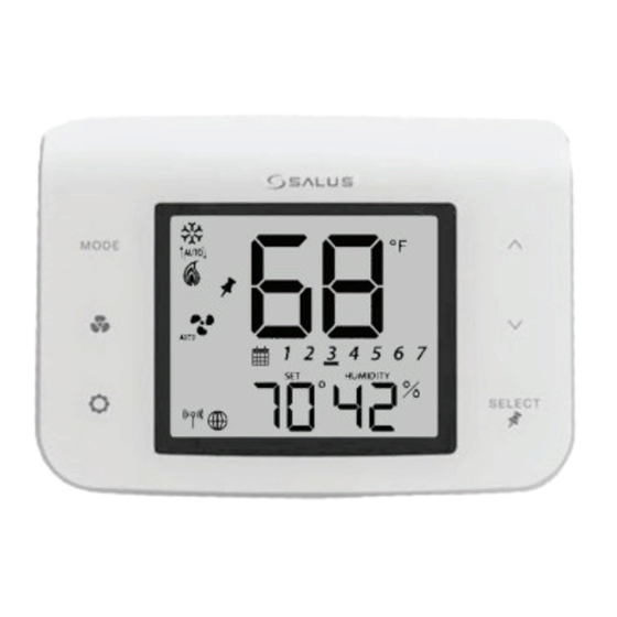
Page 14: Keypad
SC102ZB/ST103ZB Installation and Operation Manual Section 6 Device Controls – Keypad & Display Keypad SC102ZB ST103ZB Table 6.1: Keypad Functions MODE Heat, Cool, Auto, Off selection Increase Value Fan On/Auto, Low Speed, Medium Decrease Value Speed, or High Speed SELECT... - Page 15 Fixed Fan Speed – Medium Fixed Fan Speed – High Wireless/Internet Indications Device connected to local network Device connected to SALUS Smart Home Service Test/Key Lock/Battery/Filter Test Mode (Special Code 22) Keys Locked Mode Battery Low (ST103 Wireless Remote Only)
-
Page 16: Device Joining & Pairing
After installing the SC102ZB Fan Coil Controller, the ST103ZB Wireless Fan Coil Remote and any optional SS909ZB Remote Temperature Sensors, turn on electrical power to the fan coil system and SC102ZB Fan Coil Controller . When the SC102ZB Fan Coil Controller... -
Page 17: Ss909Zb Remote Temperature Sensor Preparation For Joining Network
SC102ZB/ST103ZB Installation and Operation Manual Section 7 Device Joining & Pairing SS909ZB Remote Temperature Sensor Preparation for Joining Network Remove the SS909ZB Remote Temperature Use a small screwdriver to remove the face Sensor from the Wall Plate or Desk Stand . -
Page 18: Pairing With Sg888Zb Gateway & Internet Connection
SC102ZB/ST103ZB Installation and Operation Manual Section 7 Device Joining & Pairing Pairing with SG888ZB Gateway and Internet Connection Open the SALUS Smart Home application, select the drop-down menu from the upper right of the screen and select: Settings Devices Add New Equipment Scan for New Equipment ... -
Page 19: Pairing Without Internet Connection
When the tile flips on When the Controller is linked, return to the the screen, choose “# corresponding to the dashboard by pressing the SALUS Logo . available controllers” . desired controller Once the SC102ZB Fan Coil Controller Next, the SC102ZB Fan Coil... - Page 20 . After pulling the battery tab on the MODE Press keys Use the keys ST103ZB Fan Coil Remote, it will simultaneously to enter to set digits to “00” . automatically pair with the SC102ZB . functions .
-
Page 21: Thermostat Configuration
SC102ZB/ST103ZB Installation and Operation Manual Section 8 Thermostat Configuration Settings Button Operation Pressing the SETTINGS button will allow adjustment of user selectable settings . Table 8 .1 lists the available settings and their functions . Table 8.1: Thermostat Settings * Humidity: This setting allows users to adjust the relative humidity setpoint . - Page 22 Note: This setting is available in standalone or local mode only. Note: Schedule parameters are only available in standalone or local mode . If the Fan Coil Thermostat is connected to the SALUS Smart Home application, the schedule must be programmed on your PC or smart device .
- Page 23 SC102ZB/ST103ZB Installation and Operation Manual Section 8 Thermostat Configuration Table 8.1: Thermostat Settings (continued) Schedule (Continued) Time Interval: Use the keys to set the start time for each time interval, displayed next to the calendar icon . 1st: Set the hour for the time interval start 2nd: Set the minutes for time interval start Press SELECT to move on to the heating setpoint .
-
Page 24: Special Function Codes
SC102ZB/ST103ZB Installation and Operation Manual Section 8 Thermostat Configuration Special Function Codes To access special functions, press and hold the MODE, keys simultaneously . Use the keys to scroll through the available codes . Table 8.2: Special Function Codes SELECT Identify Mode –... - Page 25 SC102ZB/ST103ZB Installation and Operation Manual Section 8 Thermostat Configuration Table 8.2: Special Function Codes (continued) SELECT Join/Leave Network – Press to join or leave a network . If the thermostat has not joined a network, the display will enter the pairing sequence .
-
Page 26: Operation
Fan Coil Thermostats, Controllers and Remotes can be operated in the following operating modes: • Standalone Mode – when SC102ZB Controller & ST103ZB Remote are paired but not connected to network • Local Mode – when disconnected from the gateway •... -
Page 27: Programmable Thermostat
SC102ZB/ST103ZB Installation and Operation Manual Section 9 Operation Programmable Thermostat (Standalone or Local Mode Only) When in Standalone or Local mode, the default operation of the Fan Coil Thermostat is as a Non- Programmable Thermostat with no scheduling capability . Changing the value of Parameter P00 (See Appendix A) to 1, changes the device to Programmable, allowing users to program a wide variety of schedule options . -
Page 28: Fan Modes
SC102ZB/ST103ZB Installation and Operation Manual Section 9 Operation Fan Modes Table 9.2: Fan Modes Fan Mode Speed Display Output Terminal Fan output is only activated when a thermostat call is present (On Call Fan) . When a call is present the fan runs at the selected speed . -
Page 29: P22 - Accessory Function
SC102ZB/ST103ZB Installation and Operation Manual Section 9 Operation P22 - Accessory Function Terminals Ac1 and Ac2 on the Fan Coil Thermostat provide output to an accessory such as a Humidifier, Dehumidifier, Heat Recovery Ventilator (HRV) or Energy Recovery Ventilator (ERV) .The built-in humidity monitor continually samples humidity at the thermostat and will operate a humidifier or dehumidifier to maintain the specified value . -
Page 30: P16 - Away Mode
SC102ZB/ST103ZB Installation and Operation Manual Section 9 Operation P16 - AWAY Mode Fan Coil Thermostat terminals Ts and Tc are used to initiate or terminate an Away state in the device . The Ts/Tc contact closure is configured by P16 as a Normally Open or Normally Closed contact, or as an input to be ignored . -
Page 31: Troubleshooting
SC102ZB/ST103ZB Installation and Operation Manual Section 10 Troubleshooting Troubleshooting The following error messages are displayed to identify issues when certain conditions occur . Table 10.1: Error Messages Error Message Description Corrective Action Error 01: Pipe supply sensor circuit is • Check connection of pipe supply sensor... -
Page 32: Installer Notes
SC102ZB/ST103ZB Installation and Operation Manual Section 11 Installer Notes Installer Notes 11-1... -
Page 33: Parameter List
SC102ZB/ST103ZB Installation and Operation Manual Appendix A Parameter List MODE, To change parameters, press and hold the keys simultaneously . Use the keys to scroll to “49” and press SELECT . Name Values Default Description/Comment 0 = Non-Programmable Type of thermostat... - Page 34 SC102ZB/ST103ZB Installation and Operation Manual Appendix A Parameter List Name Values Default Description/Comment 0 = Analog input Displayed only if P01=0 and P02=3 or 4 1 = Normally open, default mode is Heat 2 = Normally open, default mode is Cool Pipe sensor NOTE: PO2 option #3 &...
- Page 35 5: Lock Settings and HVAC Combination key pressing will not be locked at any time . 6: Lock Settings and Fan 7: Lock All * SC102ZB Controller and each ST103ZB Remote is controlled locally and can be set to different P36/P37/P44 values .
Need help?
Do you have a question about the SC102ZB and is the answer not in the manual?
Questions and answers