
Related Manuals for Salus PCSol 150


Summary of Contents for Salus PCSol 150
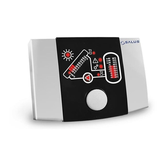
- Page 1 Controller PCSol 150 FOR SOLAR COLLECTORS INSTALLATION AND OPERATION MANUAL REVISION: 1.1 SOFTWARE: 1.xx 26-05-2015...
-
Page 3: Table Of Contents
Contents List of Figures Fig. 2.1 Functional diagram ..........4 Fig. 5.1 Controller screen ..........8 SAFE INSTALLATION AND USE ..... 4 Fig. 5.2 Collector temperature display......8 GENERAL ............ 4 Fig. 5.3 Reservoir temperature display......8 Fig. 5.4 Screen navigation..........8 DIRECTIVE WEEE 2002/96/EC ...... -
Page 4: Safe Installation And Use
Controller used only intended purpose. 2. GENERAL It is required to use auxiliary protection PCSol 150 is an advanced electronic automatics to protect hot water system (in temperature controller designed heat case of controller or software malfunction). -
Page 5: Directive Weee 2002/96/Ec
3. DIRECTIVE WEEE 2002/96/EC The product you have purchased was designed and made using the highest quality components that may be recycled and reused. If the product is marked with the above crossed bin symbol, it means that it meets requirements of the European Directive 2002/96/EC. -
Page 7: Operating Manual
OPERATING MANUAL PCSol 150... -
Page 8: Operation
Fig. 5.1 Controller screen 5.1. Temperature display Measured temperatures from both connected sensors are presented on PCSol 150 linear display indicators. Fig. 5.4 Screen navigation. Number of lit segments increases along with the Press the knob to start editing selected value. The temperature rise. -
Page 9: Temperature Presets
Press the knob (sun symbol 5.3. Temperature presets will start fast blinking) to enter value editing mode. The controller allows you to set the following You may change the value temperatures: by turning the knob. The Temperature setting for reservoir TsDHW temperature selection step is ... -
Page 10: Setting Of Deltas 4÷14
7. CONTROLLER OPERATING ALGORITHM When switched controller automatically starts to control the collector pump operation. When the T1 sensor temperature reaches minimal collector operation value (TCOLmin), the controller will enable collector pump operation. Such status is indicated by illumination of the sun symbol indicator. When the collector Fig. -
Page 11: Alarms
Cyclical discharge heat from During alarm collector temperature collector may be only up to the time when DHW indicator for 35÷75°C is blinking, while 80°C reservoir maximal temperature is reached. Then, temperature is lit steadily. the controller will not let loading heat into the T2 sensor malfunction, short circuit reservoir, even if critical temperature has been Alarm on incorrect operation or damage to T1... -
Page 12: Switching Off
The table below includes numbers of software Alarm reaching versions corresponding temperature collector maximal indications. temperature 180°C. Alarm stops collector pump Collector Number 1 Reservoir Number 2 operation. Alarm will be off temp. temp. when collector 100°C 80°C temperature drops below 90°C 75°C... -
Page 13: Installation Manual
INSTALLATION MANUAL PCSol 150... -
Page 14: Technical Data
* unit at ambient temperature of 23°C 10.1. Elements of the set 11.1. Installation of the controller The controller is designed for vertical wall- - Controller PCSol 150 1 pc. mounted installation. Mounting hole locations are - Temperature sensor T1(CT6w) 1 pc. -
Page 15: External Circuits Connection
The controller must be installed in a way that: Do not open casing by levering its cover from below. It will break the cover clip. Degree of protection is ensured suitably to environmental conditions Dust and water access is prevented Permissible operating temperature is not exceeded (40°C for controller) Air exchange inside casing is allowed... -
Page 16: Diagram Of Connections
DIAGRAM OF CONNECTIONS See below diagram of connections for PCSol 150 controller. Details of connecting to individual ports are presented in sections 12.1.2÷12.1.3 Presented hydraulic diagram will not replace central heating technical design and may be used only for informative purposes. -
Page 17: Use Of Connectors
(with a sleeve on) and then release the push. Fig. 12.3 Power supply connection 12.1.3. Temperature sensor connection PCSol 150 controller works with temperature sensors with pt1000 structure, types CT6w and Fig. 12.2 Using clamped terminals CT6, with the temperature ranges:... -
Page 18: How To Close Casing
HOW TO CLOSE CASING To close the unit casing hook the casing cover with recesses against the base insets (shown in Fig. 13.1) Fig. 12.4 Connection of temperature sensors Temperature sensors are equipped with brass coat with diameter of 6mm and 50mm long. -
Page 19: Fuse Replacement
FUSE REPLACEMENT Before fuse replacement, disconnect the unit from power supply. It is not possible to check the fuse visually. Fuse checked means ohmmeter. Infinite resistance in the fuse circuit means that the fuse is burnt and must be replaced. For the unit use sub-miniature slow blow fuse 1.25A compliant to IEC 60127 and with maximum switching current not lower than 100A. -
Page 20: Troubleshooting
TROUBLESHOOTING Symptom Remedy Controller is not working 1. Start the controller by keeping its knob depressed for at least 2 seconds 2. Check power supply 3. Check fuse in the controller Controller alarms collector 1. Collector pump runs at too low speed overheating 2. -
Page 21: Fig. 15.1 Casing Drawing For Installation Aid
Presented drawing is in 1:1 scale and it may be helpful during installation. You may cut off this page and use to mark installation place Fig. 15.1 Casing drawing for installation aid... - Page 24 SALUS Controls Made in Poland...
Need help?
Do you have a question about the PCSol 150 and is the answer not in the manual?
Questions and answers