
Related Manuals for Salus WT100


Summary of Contents for Salus WT100
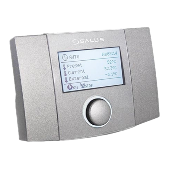
- Page 1 WEATHER CONTROLLER WT100 FOR CONTROL TEMPERATURE HEATING CIRCUIT OPERATIONS AND INSTALLATION MANUAL VERSION: 1.4 SOFTWARE VERSION: v01.XX.XX 03-2018...
-
Page 3: Table Of Contents
TABLE OF CONTENTS SAFETY INFORMATION…………………………………….. 4 GENERAL INFORMATION…………………………………. 5 INFORMATION ABOUT DOCUMENTATION………. 5 DOCUMENTATION STORAGE…………………………….5 USED SYMBOLS…………………………………………………5 WEEE DIRECTIVE 2012/19/UE………………………….. 5 OPERATING THE REGULATOR………………………….. 8 ……………….. 8 ESCRIPTION OF DISPLAY MAIN WINDOW ……………………………………. 8 ONTROLLER OPERATION USER’S MAIN MENU………………………………………… 9 ……………………………………………………... -
Page 4: Safety Information
SAFETY INFORMATION Short circuit at the outputs leads to damage to the device (not output COM- NO). Requirements concerning safety are Do not operate the unit when it is listed in particular sections of this instruction. malfunctioning repaired Apart from them it in necessary to fulfill the unauthorized persons. -
Page 5: General Information
General information - useful information and tips, Weather controller WT100 is designed to useful information concerning control the temperature in the heating circuit property damage, health or life threat for with the valve 3 or 4-way equipped with a people or pets. - Page 7 REGULATOR INSTRUCTION MANUAL WT100...
-
Page 8: Operating The Regulator
1. Regulator working modes: Operating the regulator - OFF mode controller TOUCH&PLAY system that - AUTO mode (work with clock) facilitates operation. 3sek. Encoder is operated by its - COMFORT mode rotating and pressing. - ECONOMY mode To start the controller, keep pressed encoder knob for 3 - AUTO-ECO mode seconds. -
Page 9: User's Main Menu
Continous control – preset is setting (Preset temperature - Decrease temperature of water in the heating circuit of work mode). is constant at the set value, without the Comfort - preset temperature in the impact changes external room is constant and corresponds to the temperature. -
Page 10: Summer/Winter Function
Information information menu allows view information temperatures and allows to see which devices are currently enabled. By Example time interval. turning the encoder TOUCH&PLAY changes between successive windows of information. In the example below, a “night” period will last from 00:00 till 06:00. “day” period will last Additional functions between 06:00 –... - Page 11 INSTALLATION MANUAL AND SERVICE SETTINGS WT100...
-
Page 12: Hydraulic Schemes
Hydraulic schemes Scheme 1 Hydraulic scheme with of the four-way valve controlling the central heating circuit or floor circuit Legend: TP – room thermostat (NO-NC) T1 – heating circuit temperature sensor type CT10 T2 – external temperature sensor (weather) type CT6-P T3 –... -
Page 13: Scheme 2
Scheme 2 Hydraulic scheme of the three-way valve controlling the central heating circuit (with a hydraulic coupling) Legend: TP – room thermostat (NO-NC) T1 – heating circuit temperature sensor type CT10 T2 – external temperature sensor (weather) type CT6-P T4 – hydraulic coupling temperature sensor type CT10 P –... -
Page 14: Scheme 3
Scheme 3 Hydraulic diagram of the three-way valve controlling circuit underfloor heating (with a hydraulic coupling) Legend: TP – room thermostat (NO-NC) T1 – heating circuit temperature sensor type CT10 T2 – external temperature sensor (weather) type CT6-P T4 – hydraulic coupling temperature sensor type CT10 P –... -
Page 15: Installation Of The Controller
Installation of the controller Installations regulator on the wall is shown in the picture below. Environmental conditions Due to the risk of fire is prohibited to use the controller explosive dust environment (eg. coal). Regulator should be separated using appropriate enclosure. The controller is designed for operation in the environment where... -
Page 16: External Circuits Connection
External circuits connection TP – room thermostat (NO-NC), L N PE – power supply 230V~, 50Hz, T1 – temperature sensor mixer heating circuit P – CH pump, type CT10, SM – mixer actuator, T2 – external temperature sensor type CT6- S –... -
Page 17: Connecting Electrical System
Connecting electrical system Fixing the external wires Electric cables external circuits are predicted Regulator is designed to be fed with 230V~, for the installation of surface-mounted. A 50Hz voltage. Supply connected concealed external cable outlet should be terminals L, N, PE. provided, as well as protection against the The electrical system should be: wire being pulled out, loosened or strained,... -
Page 18: Connection Of Temperature Sensors
Connection of temperature sensors Connecting weather sensor (external) Use only following sensor types: CT10, CT6-P. The use of other sensors is prohibited. The regulator cooperates only with a weather Sensors cables could be extended by a cable sensor of the CT6-P type. The sensor should with cross-sectional area min. -
Page 19: Temperature Sensor Checking
Temperature sensor checking therefore only serve to disconnect circuit voltage of 230V ~. Use separate relay in the Temperature sensors CT10, CT6-P can be event of having to disconnect circuits at low checked by measuring their resistance in voltage. given temperature. In case of big differences Risk of electric shock caused by between measured... -
Page 20: Service Menu
SERVICE MENU range fact. Protection Entrance to the service menu: Return sensor Off/On Password → [0000] → OK Min. temperature* 30..65ºC Histeresis* 2..15K Services settings range fact. Closing the valve* 0..50% Heating circuit Frost protection Off/On Heat source Frost protection delay* 1..10h Protection Frost protection temp.*... -
Page 21: Services Settings
Services settings Heating circuit Support ON or OFF supporting the heating circuit (radiators or underfloor) by the controller. Kind of the system Selecting the type of heating installation: Radiators system or Underfloor heating. Weather control – preset temperature of water circulating in the heating circuit reference is with regard to indications external temperature sensor. -
Page 22: Protection
ON – When the temperature of the heat source is lower than the Min. temperature for the circuit, the controller lowers the circuit preset temperature, but only when there is HW priority no active reduction from the operation mode. ... -
Page 23: Function
it is necessary to set the value of parameter Function Decrease by thermostat, e.g. at 2°C. After opening of the thermostat contacts, the preset Prompts mixer circuit temperature will be decreased, The controller reports on the main screen which, if proper decrease value is selected, prompts alarm indicating the status of the will stop growth of temperature in the heated controller and damage the sensors, so that... -
Page 24: Frost Protection
the building, the room temperature remains Description of frost protection against constant regardless temperature external temperature sensor outside. readings. The regulator introduced value for the heating When the external temperature drops below curve for underfloor heating: 3°C, an Frost protection delay, e.g. 4h must external t. -
Page 25: Pump Anti Standstill Function
Pump anti standstill function Technical data controller performs function Power 230V~, 50Hz protecting pump from anti standstill. It Maximum current consumption 3(3)A involves the periodic switching (which 167h with loaded outputs for a few seconds). This protects the pump Maximum current consumption against immobilization scaling. - Page 28 SALUS – Controls ul. Rolna 4 43-262 Kobielice Poland www.salus-controls.pl...
Need help?
Do you have a question about the WT100 and is the answer not in the manual?
Questions and answers