Table of Contents
Advertisement
Micro Intelligent Public Address System
User's Manual
Thank you for using DSPPA public address system. To ensure optimal operation of this equipment, please read these
operational instructions carefully before using.
Public Address System
G u a n g z h o u D S P PA A u d i o C o . L t d
1
MAG2120II
MAG2140II
http://www.DSPPA.com
http://www.dsppstech.com
Advertisement
Table of Contents

Related Manuals for DSPPA MAG2120II


Summary of Contents for DSPPA MAG2120II
- Page 1 MAG2140II User’s Manual Thank you for using DSPPA public address system. To ensure optimal operation of this equipment, please read these operational instructions carefully before using. G u a n g z h o u D S P PA A u d i o C o . L t d http://www.DSPPA.com...
- Page 2 All contents in this Operation Instructions are based on operation of MAG2140II, which are only for illustration. Furthermore, operation methods for MAG2120II are similar to that of MAG2140II. For future use, please make a good disposition of this manual...
-
Page 3: Table Of Contents
Content 1. System Overview .................................... 4 2、Performance characteristics ................................4 3、Appearance and Functions ................................5 4、Connection Description ................................8 5、Operation Instructions ..................................12 6、 Other Functions ..................................31 Packing list ......................................34 Specifications .....................................36 1 Safety Precautions ...................................37 2. Precautions for After-sale Services ............................38 ATTACHMENT ....................................39 Remote Control (Optional) ................................40... -
Page 4: System Overview
This address system falls into two types as per the number of control zone, namely MAG2120II and MAG2140II. MAG2120II and MAG2140II can control 20 and 40 zones respectively to provide more options for users. -
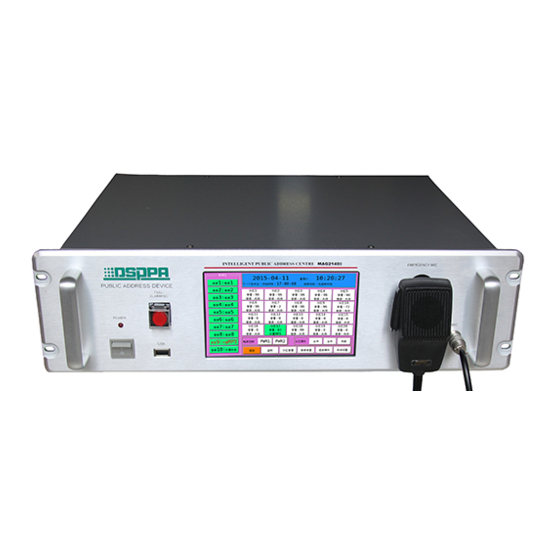
Page 5: 3、Appearance And Functions
3、Appearance and Functions Front Panel 1. Power Switch Press I and O to switch on and off the power source respectively. 1. USB Interface It is connected with such memorialize as USB stored with MP3 programs and mobile HD for copying of programs to MP3 player, which is available for plug-in of the mouse with USB plug. -
Page 6: Back Panel
3.2 Back Panel 1. 8-route Audio Source Input Interface and Volume Control Knob 8 independent audio source input channels are available for connection with 8 external audio sources. Each channel is provided with one independent volume control knob. 2. 40 Audio Matrix Output Interfaces Each audio output interface is corresponding to a zone for connection with power amplification audio input interface. - Page 7 9. Alarm link output interface 10. The power output linkage interface 11. Zone 1-20 Alarm Signal Input Interface Input signals from firefighting center. 12. Zone 21-40 Alarm Signal Input Interface Input signals from firefighting center. 13. Built-in Radio Head Module For radio head module, please refer to Connection of Radio Head Module.
-
Page 8: 4、Connection Description
4、Connection Description 4.1 Input Connection Description (Audio sources as indicated in the following figure are for illustration only; any user may proceed with connection at his or her discretion.) Audio source 7 external Audio source 6 Audio source 3 VCD Audio source 2 PC Audio source 8 external radio... - Page 9 4.2 Description of Output Connection This machine is expected to distribute 8 external audio sources and 2 built-in ones to 40 audio output ports for output to 40 zones. Each zone is provided with one set of power amplifier to receive audio signals from this machine. Refer to the following figure 40 output ports connected with power amplifiers in zone 1-40...
-
Page 10: Other Connections
Paging hub Remote paging 4.3 Other Connections Remote paging 0 Can be connected Remote pager directly Wireless remote MIC2 Alarm linkage Fire center control receiving output antenna Power linkage MIC1 output Network Outside audio source control Telephone signal Description: Make sure that placement of wireless receiving antenna is close to the receiving orientation of wireless remote controller to obtain more satisfactory receiving effect and longer receiving distance. - Page 11 4.4 Connection of Radio Module Radio function of this machine is realized by the module, which is available for separation. It is applicable to place radio module at the position of strong receiving signals for connection with extended network line so as to ensure effective improvement of receiving effect.
-
Page 12: 5、Operation Instructions
5、Operation Instructions Main Interface “Welcome! Process Starting, please waiting” will be displayed on the screen once the power is switched on to start the machine. It is applicable to enter the main interface as shown in the following figure after start-up. Current time and date... - Page 13 Figure2 MP3 player) Play operation, choose the “catalog of songs” on the left side firstly. Songs in the catalog will be displayed in the play-list on the right side. After that, proceed with setting of play mode (such as “loop play”) in the “mode selection”...
- Page 14 indicates that radio is switched to mute mode. The button will be in white color again if “MUTE” is clicked to cancel the mute mode. 3) Zone Switch Operation Zone switch is available for both individual and synchronous control. As shown in the main interface, only zone 1-20 are displayed on the interface.
- Page 15 Figure 4 Monitoring Setting It is applicable to monitor zone status by clicking zone button on the monitoring interface directly. The button will be in green color when the zone is under monitoring; whereas “×” before the speaker icon will be changed into “√”. Use “Page Rolling”...
-
Page 16: System Setting
Sound volume Click the source volume button on main interface , enter the audio volume control interface, the interface (Figure 7) shows as follows, regulate the sound volume and partition the volume control setting method of the same, this is no longer in this paper. - Page 17 interface. This aims to ensure accurate execution and operation of various system functions. Figure 9 System Setting 1) Timing setting Click “Timing Setting” button to enter the timing setting interface as shown in the following figure: This item is to be selected during timing Chime setting: Select chime signal.
- Page 18 of the button board. Input timing point, and click the “Confirm” button at the bottom to complete editing, and exit the button board. Be sure to select English or Chinese before input Figure 11 Timing point naming editor keyboard ③ Bell selection: There are 3 bell signals available for selection in the system. Click inverted triangular symbol after the “Bell”, and select bell signal on the drop down menu.
- Page 19 Selection” button to enter the program setting interface as shown in Figure (10), (11) and (12). One built-in timing point is available for timed play control of built-in MP3, built-in radio and 4 external audio source Select the directory from the top box and click here to open the directory and select tracks Set wave band and channel after.
- Page 20 trolled External source Add external device Device Program device other Device type Socket 1 Control type Playing program Click this button to add equipment as set into the list of controlled equipment Delete Delete all Return (Figure 15) Audio Sources for Timing Points ⑧...
- Page 21 exit the timing point setting interface. 2) Timing scheme In the "system settings" interface, click the "timing scheme" button to pop up the timing scheme selection interface, interface as shown in the following figure (Figure 17) .Here chose to determine a timing scheme and programming from time to time in editing the timing point will be automatically saved in the set of timing scheme.
- Page 22 button, can complete the rename edit and exit the keyboard and other operations. Delete Backspace Sound source 1 Cancel (Figure 19) keyboard editing interface 3) Program Setting (Figure 19) keyboard editing interface Click “Program Setting” on the “System Setting” interface to enter the setting interface as shown in the following figure (Figure 20): Program Setting”...
- Page 23 click “Individual Copy” button below the block to copy selected songs into the machine. In the event that catalog is displayed in the block below “USB Device”, just select certain catalog, and click “Next Catalog” below the block to enter the play list before copy programs. Tips: when insert the U disk to the device, waiting for 10 seconds until the disk program can display in the directory column.
- Page 24 5) Wireless Process Setting Click “Wireless Process Setting” button on “System Setting” interface to enter wireless process setting interface as shown in the following figure (Figure 16). This system can be controlled with wireless controller in the control mode identical to that for timing points. Remote control distance of wireless remote controller ranges from 100m to 1000m as per different environments.
- Page 25 following figure (Figure 23). The user can set password at discretion on the telephone setting interface. If it is necessary to select use of password, just input 4-digit password in the password input block. In this way, it will be applicable to input password t for calling or paging in case of incoming call.
- Page 26 Click “Audio Source Setting” on the “System Setting” interface to enter the audio source setting interface as shown in the following figure (Figure 25): (Figure25) Nomination of Audio Sources It is applicable to alter or nominate designation of each audio source on this interface. Click the block displaying designation of audio source to select certain audio source (such as CH2), and then click “Alteration”...
- Page 27 It is applicable to edit a designation for each zone on this setting interface so as to facilitate edit and management of zones in this function. Click the zone for designation editing to enter designation editing button board in case of setting. Input zone designation on the button board, and click “Confirm” button to exit the button board to complete nomination of the zone.
- Page 28 11) Language selection English and Chinese can be selected here! Chinese English Cancel 13)Machine code 12) Configuration operation This setting, configuration file are exported to the U disk, import the configuration file to the system and software upgrades, before the operation of this item, insert the U disk.
- Page 29 Click the recording operation button on the interface of system settings, entering the following (Figure 29) shows: click on the "recording" button will see “preparing to record, please wait for a moment” .when the recording is finished, click the "stop" button.
- Page 30 To regulate the screen on the touch screen settings, click the “re-regulate” screen will restart the system into the touch screen calibration; select the items on the screen protection settings, after a period of time without any operation, the screen does not display or change any screen protection, until the touch panel on the screen with touch when the screen display again.
-
Page 31: 6、Other Functions
6、Other Functions 6.1 Warning This machine aims to send warnings to individual or partial or all zones based on the input warning signals. Prerequisite for receiving external warning signals by the machine is stated as follows: It is a must to set warning level properly in “Warning Setting”... - Page 32 and select target zone on the remote pager to send remote paging to corresponding zone in this system. With regard to method for paging with remote pager, please refer to Operation Instructions for Remote Pager. Remote paging signals have level 3 priority, which can cover signals of telephone paging and background audio source.
- Page 33 3) Click the center of cross icon with nib on the screen calibration interface (note: be sure to click the center). 4)Proceed with aforesaid calibration at four corners and center of the screen. Otherwise, it will be unable to shift the cursor to the designated option during operation.
-
Page 34: Packing List
Packing list List Quantity MAG2140II(MAG2120II) Touch pen MP-P National standard power line FM antenna AM antenna and antenna pedestal Hardware MP9908 flat cover SY564 line(Crystal serial port) SY542 audio line Wireless receiving antenna 12 remote wireless remote control M5× 19 cup head cross screw... -
Page 35: Specifications
Specifications Model MAG2120II MAG2140II No. of control zone Display 5.6-inch color screen Control mode Touch screen/remote control/wireless control Input sensitivity 250mV(± 25mV) Output 1V(0dBV) Built-in audio source Radio, MP3 Frequency 20Hz-20kHz response 85dB Dynamic 90dB range Harmonic 0.05% distortion Sensitivity... -
Page 36: Safety Precautions
1 Safety Precautions Do not plug the power plug of the device into the power grid without connecting the system line. Make sure the voltage input equipment and the equipment requirements are exactly the same, or risk burning equipment. ... -
Page 37: 2. Precautions For After-Sale Services
2. Precautions for After-sale Services Our company will provide three-year free guarantee (including free replacement of parts) for any quality problem as occurred during regulated installation and normal operation as per operation instructions from the date of purchase. Any user enjoying the free guarantee is requested to present receipt of the warranty card and invoice. -
Page 38: Attachment
ATTACHMENT Notes on the application of U disk file format: 1. Due to the rapid development of the U disk and various type of memory and the market is complex and chaos, this product may not be compatible with all brands, models and specifications of the U disk on the market. -
Page 39: Remote Control (Optional)
Remote Control (Optional) 1)Installation of Remote Control Computer Software LAN interface can be connected with computers to realize remote control of the host computer through control software (realize auto play of fixed programs at fixed time and place). (Such function is to be realized by remote control software separately purchased). Any system installed with remote control software is to be attached with a remote control software installing CD at the time of delivery. - Page 40 Click “Finish” and it the installation will be done...
- Page 41 2. Computer remote control After finishing the installation of remote software with computer controller, it will generate a shortcut icon on the desktop; double click the icon to enter the next one interface: 2.1 Remote Control Operation System control interface as shown in the aforesaid figure can be used for setting of audio matrix to distribute 10 audio sources to 40 zones (20 zones for MAG2120).
- Page 42 2.2 Timing Point Setting and Synchronization Click timing point, and input password to enter the timing edit interface Mark in red represent timing point edit zone 1. As shown in the aforesaid figure, all timing points as edited are displayed in the list. Click options in the list for setting.
- Page 43 timing points. Shift the mouse to such button to display detailed help information. Download Timing Points: Download timing points on the broadcasting mainframe to current list. Synchronization to broadcast: Synchronize edited timing points to broadcasting mainframe. 2.3 Resources Nomination Zone nomination is identical to that for audio sources Click “Resources Nomination”, and input correct password to enter the setting interface...
- Page 44 2.4 Wireless Grouping Setting Click here to do the wireless grouping setting As indicated by the icon, wireless grouping falls into 3 steps: ① Select remote control key for setting. ② Display selected information on remote control key for direct setting on such interfaces. ③...
- Page 45 2.5 Telephone Setting Click “Telephone Setting”, and input correct password to enter this setting interface As shown in the figure: ○ 1 This zone is for telephone grouping setting. Click grouping list to select corresponding group for setting, and then click zone list setting to see if it has been opened. ○...
- Page 46 2.6 program management Operation instructions: Firstly, double-click in the regional radio host program list to select the programs need to modify, and then select the upload songs in the right area of the local host directory tree, after selection, click "start copy" button (or direct the hook selected file drag and drop it into the host broadcasting program list) to begin copying files and please do not carry out other operations during the copying period.
-
Page 47: System Requirements
3.1.2 System Requirements As tested, the software can support mobile phone system (tablet above version 3.0) above Android 2.1. Please do not hesitate to contact use, and indicate mobile phone model and system version if your mobile phone (tablet) is not compatible with this software. - Page 48 3.2.1.2 Setting Methods (1)Refer to operation instructions for micro intelligent mainframe, and click IP setting button on the system setting interface to enter mainframe IP address setting interface. Properly set IP address and remote control port of micro intelligent mainframe. For instance, IP address and port of the mainframe can be set as 192.168.1.211 and 8001 respectively.
- Page 49 3.2 Network Setting 3.2.1 WIFI Control (1) equipment requirements Android mobile phone (Android system), micro intelligent host, wireless router. (2) Setting method ① Read the micro smart host instructions for reference click the IP settings button in the system settings, enter the host IP address settings interface to set micro intelligent host IP address and remote control port.
- Page 50 not registered. Input the serial number in the sequence number column as shown below, and then click the "register" button. The serial number can be obtained on the CD or the host machine. Input the IP address in the IP address column (input he host's IP address), the port number to be consistent with the control port number of the host, click on the "registration"...
- Page 51 2) Remote Control Zone control: Click the button to load selected audio source at the designated zone. Click setting option for switch over to different functional modules. Power on/off Manual and Click this button to Zone full open/close button program select audio controller source.
- Page 52 3) Nomination of Audio Sources Click here to Click the selected partition select audio name recess Click the confirm button after Modify the source name and modifying the partition name. press "confirm" button Synchronize the modified audio Synchronize the modified partition list source to broadcast to broadcast.
- Page 53 Select 5) Audio Volume audio source “Select all” button to select the audio source Adjust the volume...
Need help?
Do you have a question about the MAG2120II and is the answer not in the manual?
Questions and answers