Table of Contents
Advertisement
Quick Links
Advertisement
Table of Contents

Related Manuals for LINK-MI LM-TV04M


Summary of Contents for LINK-MI LM-TV04M
- Page 1 Video Wall Controller LM-TV04M Operating Manual...
-
Page 2: Table Of Contents
Contents Chapter 1.Preface...........3 Chapter 2.Notices...........3 Chapter 3.Product Introduction......4 Chapter 4.System Parameters.........5 Chapter 5.Topological graph........6 Chapter 6.Port and Key..........7 1.Port specification..............7 2.Key specification..............7 3.Remote Control Button Specification.......8 Chapter 7.Function Description ......9 1.2X2 Installation Instructions..........9 2.Main Menu Description............11 3.Splicing Wall Setting up...........13 4.Parameter Description............13 5.Frame Blanking Description..........13 6.Screen Flipping Description..........13... -
Page 3: Chapter 1.Preface
Chapter 1.Preface Welcome to choose our products, thank you for the support of our products ! For the safety both of yourself and the equipment , please read the instruction manual carefully before using this equipment. Products are covered with a fragile label, pleasee preserve it carefully which will serve as the warranty certificate. -
Page 4: Chapter 3.Product Introduction
hard pressure. The connection line between the product and thee supporting module board can not be too long,Otherwise it may affect performance and image quality. Chapter 3.Product Introduction This product is a special LCD TV, ultra narrow LCD screen projection HD screen splicing processor, single support 4 to 16 HDMI,The utility model relates to a signal output, which is connected with a LCD television or other display devices,User can customize a variety of... -
Page 5: Chapter 4.System Parameters
Remote control support, infrared remote control can be completedd on the processor the function of setting, switching and adjusting of the remote control system,the distance is up to 7 to 10 meters. Chapter 4.System Parameters Appellation Specifications Input Signal HD15 interface;Support 640x480/85HZ to 1920x1200/60HZ;... -
Page 6: Chapter 5.Topological Graph
Chapter 5.Topological Graph... -
Page 7: Chapter 6.Port And Key
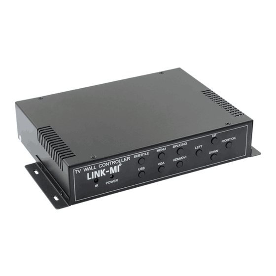
Chapter 6.Ports and Keys 1.Port Specification Input Output • DC12V:12V Power In • HDMI 1:HDMI 1 Output • RS232:RS232 In • HDMI 2:HDMI 2 Output • USB:USB Input • HDMI 3:HDMI 3 Output • HDMI:HDMI Input • HDMI 4:HDMI 4 Output •... -
Page 8: Remote Control Button Specification
3.Remote Control Button Specification Power OFF Power ON PC-RGB Signal HDMI HDMI Signal DVI Signal Volume Up Subtitle ON/OFF Volume Down SW/SP Splicing/Single INPUT Signal Source Menu ← Left → Right ↑ ↓ Down MENU MENU EXIT EXIT MUTE MUTE UPGRADE UPGRADE Packing Contents... -
Page 9: Chapter 7.Function Description
Chapter 7. Function Description 1. 2×2 Splicing Mode Setting Up Description • Put the input signal(HDMI,DVI,VGA)into the input port of the splicing box. • Put the HDMI output of the splice box is connected to the screen (no need to be in a certain order Connection). •... - Page 10 picture 2 After the adjustment, turn this splicing switcher att "open" that is the end of splicing...
-
Page 11: Main Menu Description
2. Main Menu Description : Menu1:Picture menu Menu2:Audio menu... - Page 12 Menu3:Time menu Menu4:Option...
-
Page 13: Splicing Wall Setting Up
3. Splicing Wall Setting up 1. in the main menu, choose to enter the setup menu - > stitching mode Set up. 2. press the left and right keys to select the appropriate splicing mode. 3. select the HDMI port selection, and according to the port ID select phase Location of stitching (curtain wall address). - Page 14 picture 1 In the LED settings project, you can image scaling, cutting, and other corresponding LED functions, the image will be scaled to adapt to the need to cut. As picture 2: picture 2...
- Page 15 LED Setting LED Image scaling DISP HSTAR:Select the X axis starting point for the zoomed image DISP VSTAR:Select the Y axis starting point for the zoomed image DISP WIDTH:Select the width of the zoomed image DISP HEIGHT:Select the height of the zoomed image LED Image clipping CROP HSTAR:Select the X axis coordinates for the cutting position CROP VSTAR:Select the Y axis coordinates for the cutting position...
-
Page 16: Flying Subtitle Description
8. Flying Subtitle This product has a built-in scrolling subtitles function, can be directly on the screen to send rolling subtitles, no need LED screen.. picture 1 Connect the RS232 cable to the RS232 interface of the product and open the corresponding scroll caption software,The system can perform the function rolling subtitles, and can carry out various functions of subtitles in the software text location, text size, font speed, text color, background color, etc.Can also be... -
Page 17: Chapter 8.Common Problem And Solution
Chapter 8.Common Problems and Solution When the connection is completed, the screenn has been shown "no signal" 1.Please check whether the signal line is plugged in. 2.Attempt to restart the device to recapture the signal. 3.Try to replace the signal line. The remote control does not respondd 1.Check if the remote control is abnormal. -
Page 18: Chapter 9.Guarantee Description
Chapter 9.Guarantee Description Please identify this, from the date off purchase, can enjoy one year warranty service. In addition, not contain the mail delivery fees, provide free warranty service, details are as follows: 1.Due to accidental damage, unauthorized repair,improper storage resulting in mechanical failure, are not included within the scope of the warranty. - Page 19 SHENZHEN LINK-MI TECHNOLOGY CO., LTD WWW.LINK-MI.COM E-mail: service@link-mi.com...
Need help?
Do you have a question about the LM-TV04M and is the answer not in the manual?
Questions and answers