Table of Contents
Advertisement
Quick Links
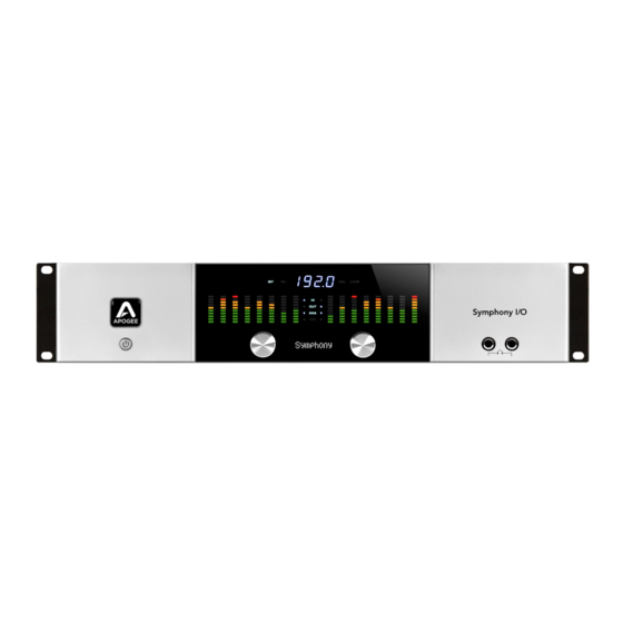
Apogee Symphony I/O
User's Guide
July 2018
Please Note: While Symphony I/O hardware and Maestro software are fully compatible with
macOS 10.9.5 and higher, Symphony I/O firmware can only be updated using macOS 10.10.5 or lower.
The Symphony I/O Firmware Updater is not compatible with macOS 10.11 or higher.
Advertisement
Table of Contents

Related Manuals for Apogee Symphony I/O


Summary of Contents for Apogee Symphony I/O
- Page 1 Please Note: While Symphony I/O hardware and Maestro software are fully compatible with macOS 10.9.5 and higher, Symphony I/O firmware can only be updated using macOS 10.10.5 or lower. The Symphony I/O Firmware Updater is not compatible with macOS 10.11 or higher. ...
-
Page 2: Table Of Contents
16 Analog Out + 16 Digital In (A16 OP) ..............2x6 Analog + AES + 8 Optical Module ..............Mic Pre Module ..................... Installing I/O Modules .................... Types of Screws in Symphony I/O ................. Directions for Installing I/O Modules ..............Auto Power-On ......................... Rack mounting Symphony I/O ................... - Page 3 ........Adjust for Volume Differences Between Speakers ..........Direct Monitoring ....................Setup Headphone/Speaker Mixes ................. Device Settings Tab Window ................. Input Routing Tab Window ..................Output Routing Tab Window ................. Standalone Routing ....................Symphony I/O - User's Guide Page 3...
- Page 4 ................How do I set my software’s I/O Buffer? ..............Troubleshooting - FAQ ....................... How do I reset Symphony I/O to its factory default settings? ......... Not getting audio input/output in my DAW ............No output from Symphony I/O ................
- Page 5 2 Symphony I/Os together with Symphony 64 Thunderbridge or PCI ? ....Symphony64 Thunderbridge/PCI not showing up after updating macOS ....Symphony I/O + AD/DA16x or Rosetta on Symphony64 Thunderbridge/PCI? ..Signal showing up in wrong place and/or routing is incorrect in Pro Tools HD ..
-
Page 6: Overview
Designed to deliver professional sound quality for audio recording, mixing and mastering, Symphony I/O is the ultimate music production centerpiece for any modern studio. -
Page 7: Package Contents
Register your product : apogeedigital.com/register • Access Apogee’s expert Technical Support for free • Receive important product update information by email • Take the Customer Satisfaction Survey for a chance to win Apogee gear! Symphony I/O - User's Guide Page 7... -
Page 8: Symphony I/O Panel Tour
Apogee icon will glow softly, indicating that Symphony I/O is in Standby. Press the power button for a half second to power up Symphony I/O. Symphony I/O may be configured to power on as soon as an AC voltage is present on the rear panel AC Input. You may find this preferable when using an external power switch (such as an equipment rack power strip) to power on the unit. -
Page 9: Rear Panel
7. USB - This USB ‘Type B’ receptacle is used to connect Symphony I/O to an Apple Mac computer. If Audio Interface Mode is set to USB Audio, audio may be streamed to and from the Mac. -
Page 10: I/O Module Cards
I/O Module Cards The Symphony I/O has a configurable chassis allowing it the flexibility for use in any environment. Two card slots can be filled by any combination of several module cards providing a solution for everyone. 8x8 Module Provides a total of 16 channels of audio input and output:... -
Page 11: 16X16 Module
- SPDIF OUT will duplicate any pair of analog or digital audio outputs. Routing of the S/PDIF Output is set with the S/PDIF Mirrors drop down menu, found in Apogee Maestroʼs Output tab window. Note: The following 16 channel cards are also compatible:... -
Page 12: 2X6 Analog + Aes + 8 Optical Module
S/PDIF Mirrors drop down menu, found in Apogee Maestroʼs Output tab window. NOTE: The Mk II and SE modules (8x8 Mk II, 16x16 Mk II, 2x6 SE) introduced for Symphony I/O Mk II cannot be used in the original Symphony I/O chassis. -
Page 13: Mic Pre Module
3. INSERTS Return 1-8 - This DB-25 connector accepts 8 analog balanced line level returns routed before each channel's A/D conversion stage. Use the INSERT sends and returns to insert analog line level gear (such as compressors and equalizers) between a channel's mic preamp and A/D conversion stage. Symphony I/O - User's Guide Page 13... -
Page 14: Installing I/O Modules
Installing I/O Modules In most cases, Symphony I/O ships with the first I/O Module installed. For the infrequent case where no I/O Modules are installed, we recommend having them installed by Authorized Symphony I/O Technicians. If you are brave enough to install them on your own, this section describes both how to install the first I/O Module as well as a second I/O Module. -
Page 15: Directions For Installing I/O Modules
Manipulating circuit boards under these conditions may result in permanent damage. a. Turn Symphony I/O off, but leave the AC cable connected. b. Ground yourself by touching the front panel of Symphony I/O to discharge static electricity. c. Unplug the AC cable from Symphony I/O. - Page 16 4. Remove the 2 screws holding the center support in place, and lift out the support. 5. Remove both I/O Module blanking panels and set the screws aside for later use. Symphony I/O - User's Guide Page 16...
- Page 17 7. Place the first I/O Module into the chassis by inserting the I/O Module rear panel into the Symphony I/O Card 1 opening, then gently dropping the front of the I/O Module into place. Line up the I/O Module's mounting holes with the 9 nuts on the bottom of the chassis.
- Page 18 I/O Module, install 9 stand-offs in the place of the 9 screws. 9. Secure the I/O Module rear panel to the chassis rear panel using the two screws from Step 4. Symphony I/O - User's Guide Page 18...
- Page 19 Module. Be sure to align the key on each ribbon cable connector to the key slot on each receptacle. 12. To install a second Module, insert the I/O Module rear panel into the Symphony I/O Card 2 opening, then gently dropping the front of the I/O Module into place. Line up the second I/O Module's mounting holes with the tops of the 9 stand-offs.
- Page 20 15. Reserving the steps to remove the cover, slide it back into place and secure with the 11 screws removed in Step 2. Use 6 undercut screws to secure the cover bottom and 5 round head screws to secure the cover's rear tab. Symphony I/O - User's Guide Page 20...
-
Page 21: Auto Power-On
Auto Power-On To configure Symphony I/O to power on as soon as AC power is present on the rear panel AC input, follow these steps. Auto Power is useful in circumstances where an external power switch is used to power on multiple devices, such as a rack of Symphony I/Os with a master power switch. -
Page 22: Rack Mounting Symphony I/O
Rack mounting Symphony I/O Rack ears are included in the Accessories box for mounting Symphony I/O in a standard 19” equipment rack. 1. Orient one rack ear to line up the ear's three holes with three holes found on the side of the chassis immediately behind the front panel extrusion. -
Page 23: Connecting Analog Inputs
8x8 or 16x16 module. The signal is then routed up through the Mic-Pre module after setting the input channels to ‘Mic’ or ‘Inst’ in the Apogee Maestro 2 software. Be sure that you don’t connect your inputs to the Insert Sends and Returns on the Mic-Pre module. See next page for details. -
Page 24: Connecting Inputs To The Mic-Pre Module
3. INSERTS Return 1-8 - This DB-25 connector accepts 8 analog balanced line level returns routed before each channel's A/D conversion stage. Use the INSERT sends and returns to insert analog line level gear (such as compressors and equalizers) between a channel's mic preamp and A/D conversion stage. Symphony I/O - User's Guide Page 24... -
Page 25: Connecting Analog Outputs
0dB. You could also do this in the Apogee Maestro app by going to the Output tab, scrolling over to the right, and raising the level to 0dB with the Main output’s software knob or changing the output format from Speaker to Line. -
Page 26: Audio Interface Modes
AIMs, although you can use all four if you would like. The Symphony I/O can only be in one AIM at a time, so when you switch to a different AIM (shown below), the unit will restart itself in the new AIM. -
Page 27: Symphony Aim
Symphony AIM Requirements Requirements when connecting to Symphony 64 ThunderBridge or PCI card: • Apogee Symphony 64 ThunderBridge or PCI card (sold separately) • mac OS Mavericks 10.9.5 or greater (64-bit and 32-bit kernel modes) Symphony System Release Package 5.3 (download from Apogee website) •... -
Page 28: Getting Started
(or using a standard IEC cable for your territory). The DC power supply accepts AC from 90-250 volts. 2. Connect the Main Symphony port of your Symphony I/O to Symphony 64 ThunderBridge Port 1: CH 1-32 and power on the connected unit. - Page 29 6. Confirm that your Symphony I/O is in ‘Symphony’ mode by pushing in and holding on the right-side front- panel encoder knob, scrolling through the different Audio Interface Modes until it shows ‘Symphony’, and then pushing in on the encoder knob again to restart the unit in the ‘Symphony’ mode.
-
Page 30: Connecting To Symphony 64 Pcie Card (Sold Separately)
8. Once the card is installed, re-attach the PCI bracket to secure the Symphony 64 card. Symphony I/O - User's Guide Page 30... - Page 31 9. Re-install the Mac’s side panel. 10. Using the 3 meter PC-32 cable included with the Symphony 64 card, connect the Symphony I/O’s Main port to the Symphony 64 PCI card’s Channels 1-32 port as shown below. 11. Power up your Mac and the Symphony I/O.
-
Page 32: Download And Install Software
Symphony I/O Software from Apogee’s website: www.apogeedigital.com/support/symphony-io 1. Connect Symphony I/O to your Mac’s USB with the USB cable that was included with the Symphony I/O. Connect Symphony I/O to your Symphony 64 ThunderBridge or PCIe card if you’re going to be using it in Symphony mode. - Page 33 6. In Audio MIDI Setup, make sure that ‘Symphony64′ (PCIe or ThunderBridge) is selected in the left-side column. In the ‘Source’ menu on the right, choose ‘Port 1: 32ch’ if you are using 1 Symphony I/O. Quit Audio MIDI Setup and restart the computer.
-
Page 34: Software Setup
0dB. You could also do this in the Apogee Maestro app by going to the Output tab, scrolling over to the right, and raising the level to 0dB with the Main output’s software knob or changing the output format from Speaker to Line. -
Page 35: Select Symphony In Your Daw
Logic, the labels you see in Logic’s Channel Strip input and output slots correspond exactly to Symphony I/O’s hardware inputs and outputs, making I/O assignment much easier. a) In Logic, choose Mix > I/O Labels 2. - Page 36 1. Go to Setup > Playback Engine. that have been provided by its driver in ProTools, the labels you see in Pro Tools’ Channel Strip input and output slots correspond exactly to Symphony I/O’s hardware inputs and outputs, making I/O assignment much easier.
-
Page 37: Monitoring The Input Signal
2. Make sure the Software Monitoring is checked in the monitoring. Preferences > Audio > Devices menu. 3. Select the “ I ” button in each track you’d like to input monitor. Symphony I/O - User's Guide Page 37... - Page 38 USB AIM (page 45) Standalone AIM (page 52) If you don’t need to set up your Symphony I/O in any of the three additional AIMs and would like to skip ahead to the other parts of the User’s Guide, you can go to: Maestro - Control software for Symphony I/O’s parameters and routing (page 54)
-
Page 39: Pro Tools Hd Aim
Digital audio and clock configuration data, such as the session sample rate and hardware clock source, is transmitted via the PC-32 cable (referred to as a DigiLink cable in Pro Tools documentation). Software control data between Symphony I/O Apogee Maestro software is transmitted via a USB connection. -
Page 40: Getting Started
Making Connections In Pro Tools HD AIM, each i/o module installed in the Symphony I/O will emulate one Avid HD I/O- example: a Symphony I/O with an 8x8 module installed in the Primary slot and a 16x16 module installed in the Secondary slot will appear as two Avid HD I/Os in Pro Tools HD/Ultimate. - Page 41 • Use a regular DigiLink cable (PC32) to connect the Symphony I/O’s Main port to an HD Core or Accel card. • Do not daisy chain Symphony I/O with other units. This includes Avid interfaces. Avid interfaces and Symphony I/O interfaces must be connected to separate ports.
-
Page 42: Setup Steps
Pro Tools software. Control over any other parameters can be done by installing ‘Apogee Maestro’ and connecting your Symphony I/O to your Mac via USB (if using Pro Tools on a PC, the Symphony can still be connected to a Mac via USB for software control through Apogee Maestro). - Page 43 0dB (make sure you’re not setting the headphones to 0dB). • You can launch ‘Apogee Maestro’ from your Applications folder if you are connected to the Mac via USB, go to the ‘Output’ tab, scroll all the way to the right until you see the Main Output control knob (with the speaker icon), and click on the drop-down menu and change the selection to ‘Line’.
- Page 44 USB AIM (page 45) Standalone AIM (page 52) If you don’t need to set up your Symphony I/O in USB or Standalone AIMs and would like to skip ahead to the other parts of the User’s Guide, you can go to: Maestro - Control software for Symphony I/O’s parameters and routing (page 54)
-
Page 45: Usb Aim
Note: When a Symphony I/O is in USB AIM, it can use a max of 16 inputs and 16 outputs. This is important to note, in case you have two i/o modules installed and you don’t have access to some or all of your i/o on the second module. - Page 46 3. After your Mac restarts, click ‘Yes’ to choose Symphony I/O : USB for Mac sound input and output. 4. If you receive a ‘firmware mismatch’ dialog that says your Symphony I/O’s firmware is not up-to-date, the firmware will need to be updated on a Mac running Mac OS 10.10.5 or below. Never attempt a “force-update” if the firmware is already up to date.
-
Page 47: Software Setup
0dB. You could also do this in the Apogee Maestro app by going to the Output tab, scrolling over to the right, and raising the level to 0dB with the Main output’s software knob or changing the output format from Speaker to Line. -
Page 48: Select Symphony In Your Daw
I/O assignment much easier. a) In Logic, choose Mix > I/O Labels 2. In the Devices Tab, select Symphony I/O : USB Audio in the Output and Input Device drop-down boxes. b) Type Command-A to Select All... - Page 49 Select Symphony in Pro Tools 5. By selecting the Symphony I/O’s input and output labels that have been provided by its driver in ProTools, the labels you see in Pro Tools’ Channel Strip 1. Go to Setup > Playback Engine.
-
Page 50: Monitoring The Input Signal
2. Make sure the Software Monitoring is checked in the monitoring. Preferences > Audio > Devices menu. 3. Select the “ I ” button in each track you’d like to input monitor. Symphony I/O - User's Guide Page 50... - Page 51 User’s Guide contains: Standalone AIM (page 52) If you don’t need to set up your Symphony I/O in Standalone AIM and would like to skip ahead to the other parts of the User’s Guide, you can go to: Maestro - Control software for Symphony I/O’s parameters and routing (page 54)
-
Page 52: Standalone Aim
(A 16x16 Analog I/O module will simply default its routing to Analog In to Analog Out and vice versa). As soon as a Symphony I/O is put into Standalone AIM, the Standalone A/D-D/A routing is already routed so it’s ready to use without any software. -
Page 53: Getting Started
Getting Started 1. Power up the Symphony I/O and make sure it’s in Standalone AIM by pushing in and holding on the right-side front-panel encoder knob and scrolling through the different modes with the knob until you get to ‘Standalone’ and then push in on the knob again to restart the unit in Standalone AIM. -
Page 54: Maestro
Maestro Apogee Maestro is a controller software for your Symphony I/O. Though you do not need Maestro open to use your Symphony I/O, it provides access to all of Symphony’s settings and parameters. Its level meters are also a useful diagnostic tool to see which inputs and outputs are receiving and sending signal. -
Page 55: Input Tab Window
- To use the S/PDIF Coax input, itʼs necessary to select another analog or digital 9. S/PDIF Replaces channel pair which the S/PDIF Coax input will replace on the Input Routing grid. Use this drop down menu to select the channel pair to be replaced. Symphony I/O - User's Guide Page 55... -
Page 56: Mic Pre Module Input Tab Window
- Use this button to enable 48 volt phantom power on the corresponding Analog IN channel. Condenser mics require 48 volt phantom power to operate. 7. High Pass - Use this button to engage an 80Hz high-pass filter on the input. Symphony I/O - User's Guide Page 56... -
Page 57: Output Tab Window
- Displays or hides the Trim faders 3. Reset Trims - Resets all Trim faders. - When calibrating Symphony I/O, use this drop down menu to choose the 4. Analog Ref Level analog reference level for each D/A conversion channel. Option-select any channel to set the analog reference for all channels. -
Page 58: Speaker & Headphone Controls
7. HP 1 Routing Selects the software outputs you want routed to Headphone Out 1. 8. HP 2 Routing Selects the software outputs you want routed to Headphone Out 2. Symphony I/O - User's Guide Page 58... -
Page 59: Monitor Control Center
Monitor Control Center Symphony I/O is equipped with several monitoring features to provide for your monitoring needs. How to set the Monitor Outputs as a fixed Line-Out This setting changes the Monitor Outputs from a variable volume controlled by the Output Controller knob to a fixed output at the full +4dBu or -10dBV reference level. -
Page 60: How To Setup And Use Multiple Speaker Sets
4. Click the Speaker Set 1, 2, or 3 button to select which speaker set is active. Note: To activate multiple speaker sets simultaneously, hold down [command ⌘] and select another speaker set button. Symphony I/O - User's Guide Page 60... -
Page 61: How To Connect & Configure A Surround Speaker Setup
2. Open Maestro and click the “Output” tab (or use the keyboard combination [⌘+2]). NOTE: When a 8x8 or 16x16 module card is in the bottom Module 1 slot, an additional option for 7.1 becomes available. Symphony I/O - User's Guide Page 61... -
Page 62: Adjust For Volume Differences Between Speakers
1. Open Maestro and select the Output tab window. 2. Select the ‘Show Trims’ button. 3. Decrease or Increase the trims for the outputs connected to speakers that need adjusting. Symphony I/O - User's Guide Page 62... -
Page 63: Direct Monitoring
NOTE: The Mixer’s location on the grid will vary based on the Module Card(s) installed. 3. In the Output tab, make sure your Headphones are set to mirror whatever hardware output you assigned Mixer 1 to. Symphony I/O - User's Guide Page 63... -
Page 64: Setup Headphone/Speaker Mixes
5. Mixer 1 will be the speaker mix and Mixer 2 will be the Headphone mix. Adjust the mixer channel faders, pan controls, and other settings to achieve the sound desired in each Mixer. Symphony I/O - User's Guide Page 64... -
Page 65: Device Settings Tab Window
Device Settings Tab Window 1. This section displays what Audio Interface Mode (AIM) the Symphony I/O is currently in. 2. This section allows you to change what metering is displayed in each bank on the front-panel. 3. If you have a module with optical i/o installed, this section allows you to toggle between ADAT/SMUX and SPDIF optical formats. -
Page 66: Input Routing Tab Window
Input Routing Tab Window The Input Routing tab window determines how Symphony I/O hardware inputs are routed to audio software inputs. The number of input channels that are available to a computer recording program is determined by Symphony’s driver. The Input Routing window determines how Symphony’s physical hardware inputs are routed to these software inputs. -
Page 67: Output Routing Tab Window
Output routing grid. Note that each marker represents an odd-even pair of audio signals - it’s not possible to route the odd and even signal of a pair to different destinations. Symphony I/O - User's Guide Page 67... -
Page 68: Standalone Routing
In Standalone mode, the PC-32 audio streams (to and from a Symphony 64 card) are not active, and thus don't appear on the grid. If multiple Symphony I/O in Standalone audio interface mode are detected, a separate Standalone Routing grid is displayed for each interface. -
Page 69: Mixer Tab Window
7. Software Return You can click on the dropdown menu below to assign a software output to it. - Stereo Master fader for Mixer. You would typically leave this at 0. 8. Mixer Master Symphony I/O - User's Guide Page 69... -
Page 70: System Setup Tab Window
* Only available in Symphony & Standalone AIMs. In Pro Tools HD AIM, clock source is selected in Pro Tools. USB AIM is always Internal. ** Only available in Symphony & Pro Tools HD AIMs. *** Only available in Symphony AIM. Symphony I/O - User's Guide Page 70... -
Page 71: Clocking With External Equipment
• The sample rate must match on both devices. Though the Slave device may automatically switch to the appropriate sample rate, this may not always occur and the sample rate will need to be set manually. Symphony I/O - User's Guide Page 71... -
Page 72: Configure Symphony As Clock Slave
When this happens, check your connections for a bad or misconfigured cable, and make sure the sample rate of the master and slave devices are set to the same value. Symphony I/O - User's Guide Page 72... -
Page 73: Menu Bar Menus
Menu Bar Menus About Apogee Maestro - Choose this menu item to display version information for all the hardware connected and software elements installed on your Mac. Preferences - Choose this menu item to display Maestro’s Preference panel. • Launch Maestro automatically when connecting a device - This launches Maestro when an Apogee device is connected to the computer. -
Page 74: Calibrating Symphony I/O
Calibrating Symphony I/O Symphony I/Oʼs A/D and D/A converters may be calibrated to operate at optimum levels with a wide variety of analog gear. The calibration process is performed in the following three steps: 1. Choose Analog Input and Output Levels 2. -
Page 75: Soft Limit
Soft Limit Soft Limit is Apogeeʼs proprietary analog process for taming transients before A/D conversion. By gently rounding transients in a transparent manner, itʼs possible to maximize level BEFORE the A/D conversion stage and prevent unwanted distortion from clipping. Soft Limit Settings Soft Limit may be engaged on each analog input in Maestroʼs Input tab window. -
Page 76: Digital I/O Formats
The S/PDIF Coax Output is “tapped” from one of the other analog or digital stereo output pairs. Use the S/PDIF Coax Mirrors drop down menu, in Maestro’s Output tab, to choose which analog or digital stereo output pair will be duplicated on the S/PDIF Coax Output. Symphony I/O - User's Guide Page 76... -
Page 77: Meters
Front Panel Meters Symphony I/O includes 2 banks of 8 level meters on the front panel. Select the audio signals to be displayed on each bank using the Meters buttons in the Device Settings tab window. Symphony I/O - User's Guide... -
Page 78: Vbus - Symphony Aim
Working with VBus Apogee's VBus is only available when Audio Interface Mode is set to Symphony. VBus creates virtual hardware buses to allow expanded routing of audio within one application or between different audio applications. For example, it’s possible in Logic Pro to record a submix of multiple audio tracks onto a new audio track as described below. -
Page 79: Reference
Now, with a 24-bit system (such as Symphony I/O), the noise floor is so low that thereʼs no real penalty for undershooting the gain setting and recording at a lower level. There IS a penalty for overshooting the gain setting - a digital Over that results in significantly increased distortion. -
Page 80: Understanding Latency
Because of the audio application’s latency, the vocalist hears his performance delayed by several milliseconds in his headphones. Symphony I/O - User's Guide Page 80... -
Page 81: How Does Maestro Resolve Latency
Symphony uses the very efficient Thunderbolt™ 2 Technology. If you’ve set your audio software’s input/output buffers according to the guidelines below and latency doesn’t bother you or other performers, there’s no need to use the Maestro mixer. Symphony I/O - User's Guide Page 81... -
Page 82: How Do I Set My Software's I/O Buffer
If you do encounter clicks, pops or software errors, don’t hesitate to experiment with the Buffer setting. Symphony I/O - User's Guide Page 82... -
Page 83: Troubleshooting - Faq
Yes. 5. This completes the hardware reset of Symphony. Not getting audio input/output in my DAW If you’re not able to get any audio input/output in your DAW with Symphony I/O, there are a couple things to check: •... -
Page 84: No Output From Symphony I/O
Level? If the first 2 analog outputs of Symphony I/O are too low in level or are muted, it is important to keep in mind that the first 2 analog outputs on Symphony I/O will default to -20dB and can be muted or dimmed, as many people use Symphony I/O as their monitor controller. -
Page 85: Exclamation-Mark (!) On Front-Panel/Symphony Doesn't Show Up In Maestro
Now plug in and unplug the cable to the ‘Main’ port of the Symphony I/O. Do this about 20 times, so the port gets clean. Now repeat this with the Main port on the Symphony 64 PCIe or Thunderbridge. -
Page 86: Is Symphony Mobile Still Supported
The Loop Sync option in the Maestro software’s System Setup tab will disappear under certain conditions. • Loop Sync is not available when Symphony I/O is in Standalone AIM or USB AIM. • When in Symphony AIM, if a legacy converter is connected to the other port on the Symphony64PCI or Thunderbridge card, Loop Sync will disappear. -
Page 87: Symphony I/Os Together With Symphony 64 Thunderbridge Or Pci
Symphony64 Thunderbridge or PCIe card using a PC-32 cable. Connect one end of the cable to the “main port” on the back of the first Symphony I/O and the other end of the cable to the 1st port (on the left) of the Symphony64 Thunderbridge or PCIe card. -
Page 88: Symphony I/O + Ad/Da16X Or Rosetta On Symphony64 Thunderbridge/Pci
Thunderbridge or PCIe card using a PC-32 cable. Connect one end of the cable to the “main port” on the back of the first Symphony I/O and the other end of the cable to the 1st port (on the left) of the Symphony64 Thunderbridge or PCIe card. -
Page 89: Signal Showing Up In Wrong Place And/Or Routing Is Incorrect In Pro Tools Hd
Tools HD? When using a 2×6 i/o module in a Symphony I/O, the 2×6 i/o module shows up as a 16ch Avid HD I/O in Pro Tools HD. Here is how the I/O corresponds with the ProTools I/O (Note that PT inputs 3 through 6 are nothing. -
Page 90: Delay Compensation With Pro Tools Hd
Using Symphony I/O & HD I/O together When using Symphony I/O with an HD I/O, delay through all tracks is equal IF HD I/O inputs are routed only to HD I/ O outputs and Symphony I/O inputs are routed to Symphony I/O outputs.When signal paths use a mix of HD I/O and Symphony I/O inputs and outputs, delay differences of a few samples will occur. -
Page 91: Mic Pre Module Faq
A. No. It only provides the option of selecting a mic pre to your existing card in slot 1. For example: If you have an 8×8 module in slot 1 of your Symphony I/O, this provides you with 8 channels of analog line-level input. -
Page 92: Pin Out Diagrams
Pinout for Analog IN (8x8 module, 16x16 module) and INSERTS RETURN 1-8 (Mic Pre I/O Module) Pinout for Analog OUT (8x8 module, 16x16 module, 2x6 module) and INSERTS SEND 1-8 (Mic Pre I/O Module) Symphony I/O - User's Guide Page 92... -
Page 93: Aes In/Out
AES IN/OUT Pinout for AES IN/OUT (8x8 module) Symphony I/O - User's Guide Page 93... -
Page 94: Specifications
Dynamic Range: 129dB A weighted Max output levels - ∞ to +24dBu Frequency response at 44.1 kHz: dc to 20kHz (+/- 0.05dB) Output impedance: 25 Ohm Outputs are balanced through Apogee's proprietary Perfect Symmetry Circuitry (PSC) Headphones: THD+N: -105dB @19dBu... -
Page 95: Additional Support
It’s never been easier to get back to work. As a ProCare member you’ll have premium access to Apogee’s world-class technical support group for the life of your agreement. The contract is fully transferable by the original registered owner of the agreement. All Apogee support technicians reside and are continuously trained at Apogee Electronics, Santa Monica, CA. -
Page 96: Warranty Information And Legal Notices
This warranty is void if Apogee determines, in its sole business judgment, the defect to be the result of abuse, neglect, alteration or attempted repair by unauthorized personnel. The warranties set forth above are in lieu of all other warranties, expressed or implied, and Apogee specifically disclaims any and all implied warranty... -
Page 97: Declarations Of Conformity
In the event your Symphony needs to be upgraded or repaired, it is necessary to contact Apogee prior to shipping, and a Return Materials Authorization (RMA) number will be assigned. This number will serve as a reference for you and helps facilitate and expedite the return process. - Page 98 Cet appareil numérique de la classe B respecte toutes les exigences du Règlement sur le matérial brouilleur du Canada. Declaration of Conformity – CE Apogee Electronics Corporation hereby declares that the product, the Symphony, to which this declaration relates, is in material conformity with the following standards or other normative documents: • EN50081-1/EN55022; 1995 •...
- Page 99 Symphony I/O - User's Guide Page 99...
Need help?
Do you have a question about the Symphony I/O and is the answer not in the manual?
Questions and answers