Sign In
Upload
Download
Table of Contents
Contents
Add to my manuals
Delete from my manuals
Share
URL of this page:
HTML Link:
Bookmark this page
Add
Manual will be automatically added to "My Manuals"
Print this page
×
Bookmark added
×
Added to my manuals
Manuals
Brands
Clear-Com Manuals
Intercom System
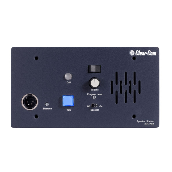
KB-702
User manual
Clear-Com KB-702 User Manual
Two channel remote station
Hide thumbs
Also See for KB-702
:
Instruction manual
(28 pages)
1
2
Table Of Contents
3
4
5
6
7
8
9
10
11
12
13
14
15
16
17
18
19
20
21
22
23
24
25
26
27
28
29
30
31
32
page
of
32
Go
/
32
Contents
Table of Contents
Troubleshooting
Bookmarks
Table of Contents
Table of Contents
Important Safety Instructions
1 Compliance
2 Operation
Introduction
Description
Operation
3 Installation
4 Maintenance
Block Diagram for the KB-702
Block Diagram for the KB-702GM/KB-802GM-IM
Troubleshooting
5 Technical Specifications
KB-702/KB-702GM/KB-802GM-IM Two-Channel Speaker Stations
6 Technical Support and Repair Policy
Technical Support Policy
Return Material Authorization Policy
Repair Policy
Advertisement
Quick Links
1
Installation
2
Block Diagram for the Kb-702
3
Block Diagram for the Kb-702Gm/Kb-802Gm-IM
Download this manual
See also:
Instruction Manual
User Guide
KB-702 and KB-702GM/
KB-802GM-IM
Two Channel Remote Station
User Guide
Part Number: 399G259 Rev A
Date: May 24, 2018
Table of
Contents
Previous
Page
Next
Page
1
2
3
4
5
Advertisement
Table of Contents
Need help?
Do you have a question about the KB-702 and is the answer not in the manual?
Ask a question
Questions and answers
Related Manuals for Clear-Com KB-702
Intercom System Clear-Com KB-702GM Instruction Manual
Two-channel speaker stations (28 pages)
Intercom System Clear-Com Encore Instruction Manual
(53 pages)
Intercom System Clear-Com KB-111A Instruction And Service Manual
Speaker station (13 pages)
Intercom System Clear-Com KB-111 Instruction And Service Manual
(17 pages)
Intercom System Clear-Com CS-100 Instruction And Service Manual
(17 pages)
Intercom System Clear-Com KB-802GM-IM User Manual
Two channel remote station (32 pages)
Intercom System Clear-Com RM-702-IM User Manual
Two channel remote station (43 pages)
Intercom System Clear-Com ENCORE MS-702 Instruction Manual
Two-channel main station (32 pages)
Intercom System Clear-Com FSII-TCVR-IP-19-US User Manual
For eclipse (111 pages)
Intercom System Clear-Com RS-700 Series Quick Refernce Manual
(3 pages)
Intercom System Clear-Com FreeSpeak II User Manual
(143 pages)
Intercom System Clear-Com Eclipse HX-Median User Manual
(161 pages)
Intercom System Clear-Com FreeSpeak II User Manual
Base station system wireless intercom system (106 pages)
Intercom System Clear-Com Eclipse HX User Manual
(259 pages)
Intercom System Clear-Com ICS-102 Instruction Manual
Intercom panel (81 pages)
Intercom System Clear-Com HME DX210 Operating Instructions Manual
Dual-channel wireless intercom (43 pages)
This manual is also suitable for:
Kb-702gm
Kb-802gm-im
Table of Contents
Print
Rename the bookmark
Delete bookmark?
Delete from my manuals?
Login
Sign In
OR
Sign in with Facebook
Sign in with Google
Upload manual
Upload from disk
Upload from URL


Need help?
Do you have a question about the KB-702 and is the answer not in the manual?
Questions and answers