
Subscribe to Our Youtube Channel
Related Manuals for HindlePower UMC Series


Summary of Contents for HindlePower UMC Series
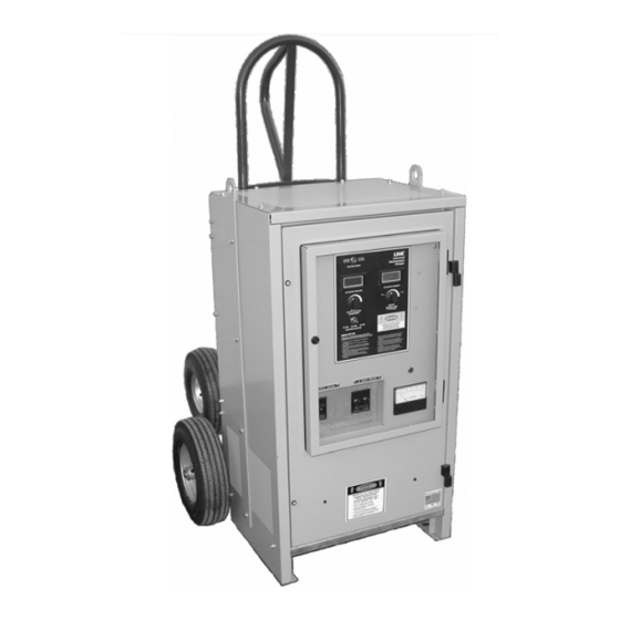
- Page 1 UMC SERIES Operating and Service Instructions UNIVERSAL MAINTENANCE CHARGER 120/208/240/480 Vac SINGLE PHASE INPUT 24/48/130 Vdc ADJUSTABLE OUTPUT JA5041-01...
-
Page 2: Quick Startup
QUICK STARTUP TURN OFF ALL POWER AND TURN OFF UMC'S INPUT & OUTPUT CIRCUIT BREAKERS (CB1 & CB2) 1. Move input jumpers on I/O panel to match the required input voltage. See connection chart on wiring diagram inside enclosure. 2. Connect the input terminals (TB1-L1/L2) to available ac power. 3. -
Page 3: Important Safety Instructions
IMPORTANT SAFETY INSTRUCTIONS Before using the battery charger, read all instructions and cautionary markings on: A) battery charger, B) battery, C) equipment connected to charger and battery This manual contains important safety and operating instructions, and therefore should be filed for easy access. -
Page 4: Table Of Contents
TABLE OF CONTENTS Page No. SECTION I • Quick Startup......................Inside Front Cover • Notes And Warnings ....................Inside Front Cover • Specifications ......................Inside Front Cover • Important Safety Instructions ....................... i • Table Of Contents (this page) ......................ii SECTION II - Installation And Operation •... -
Page 5: Section Ii - Installation And Operation
UNIVERSAL MAINTENANCE CHARGER (UMC) INSTALLATION AND OPERATION 1. BATTERY SAFETY NOTICE ...! WARNING... BATTERIES CONTAIN DANGEROUS CHEMICALS AND PRODUCE HYDROGEN GAS DURING CHARGING! THIS EQUIPMENT (UMC) SSHOULD BE CONNECTED AND DISCONNECTED WITH CARE. ALWAYS OPEN THE DC BREAKER (CB2) BEFORE CONNECTING OR DISCONNECTING THE BATTERIES, SO THAT NO SPARK OR ARC WILL OCCUR AT THE BATTERY TERMINALS. -
Page 6: Installation
3. INSTALLATION Location: Select a clean, dry location for the battery charger. It may be located in the battery room, but not over the battery, and must be upright. The openings for ventilation in the top, bottom and sides of the cabinet should not be obstructed, as they provide cooling and ventilation. -
Page 7: Maintenance
7. MAINTENANCE This charger requires a minimum of maintenance. There are no rotating parts and most components have an indefinite life with no expected aging effect. Large electrolytic capacitors (C1, C2) have a 20-year expected service life. They should be replaced when the output ripple voltage exceeds 500 mVrms, measured with a resistive load. -
Page 8: Caution
UNIVERSAL MAINTENANCE CHARGER (UMC) TROUBLESHOOTING AND REPAIR ...! CAUTION... Before troubleshooting, always isolate and deenergize the charger by opening the ac circuit breaker (CB1) and the dc circuit breaker (CB2). This avoids the possibility of personnel injury or equipment damage from high short circuit currents..NOTICE... -
Page 9: Testing Of Components
3. TESTING OF COMPONENTS a. Power Transformer (T1) With the ac and dc circuit breakers open or OFF, open the cabinet and carefully check the line voltage across line terminals on TB1, terminals L1 to L2 (do not confuse terminals L1 and L2 with the inductor components, also labeled L1 and L2). -
Page 10: Section Iv - Replacement Components
g. DC Ammeter (M1) The charger’s dc ammeter (M1) measures a shunt (R13) connected in series between the charger’s output and battery. The shunt is a 100A / 100mV shunt or 50A / 50mV shunt, depending on the model. But in either case the signal is 1mV for every Ampere out. -
Page 11: Section V - Document Control Information
UNIVERSAL MAINTENANCE CHARGER (UMC) DOCUMENT CONTROL INFORMATION DOCUMENT NUMBER The text and graphics contained within this manual are controlled by the battery charger manufacturer's internal part number (JA5017-00). The revision level and dates of this manual's text and graphics are featured in the electronic filename listed below. - Page 12 UMC SERIES Address: 1075 Saint John Street Easton, PA 18042-6661 Phone: 610.330.9000 Fax: 610.330.8510 Online: www.hindlepowerinc.com (http://www.atseries.net/HindlePower/JA5041-01.pdf) JA5041-01 - Rev. 08-2021...
Need help?
Do you have a question about the UMC Series and is the answer not in the manual?
Questions and answers