
Related Manuals for Toyotomi CFT 35 INV-Ri


Summary of Contents for Toyotomi CFT 35 INV-Ri
- Page 1 MODEL: CFT 35 INV-Ri CFT 50 INV-Ri CFT 70 INV-Ri CFT 100 INV-Ri CFT 140 INV-Ri CFT 170INV-Ri...
- Page 2 TLC-I-2011.1 Contents Part 1 General Information……………………………………………..……………………………1 Part 2 Indoor Units…………………………………………………………………………………..8 Part 3 Outdoor Units……………………………………………………………………………….122 Part 4 Installation………………………………….…………………………….……..…………..165 Part 5 Control……………………………………………………..…………………………….…231 Part 6 Control Function…………………………………………..…………………………….…262 Manufacture reserves the right to discontinue, or change at any time, specifications or designs without notices and without incurring obligations.
-
Page 3: Part 1 General Information
TLC-I-2011.1 Part 1 General Information 1. Model Names of Indoor/Outdoor Units ......2 2. External Appearance ............4 3. Nomenclature ..............6 4. Features ................7... -
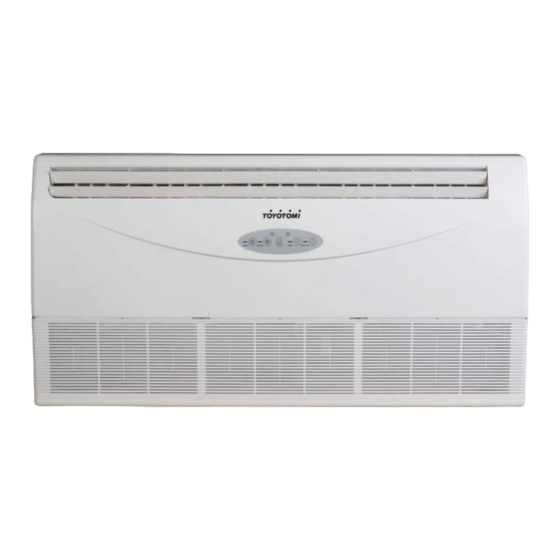
Page 4: Model Names Of Indoor/Outdoor Units
220~240V-1ph-50Hz DCT 100 INV-Si 1140×270×775 41/46 220~240V-1ph-50Hz DCT 140 INV-Si 1200×300×865 49/55 220~240V-1ph-50Hz DCT 170 INV-Si 1200×300×865 49/55 220~240V-1ph-50Hz CFT 35 INV-Ri 990×203×660 27/33 220~240V-1ph-50Hz CFT 50 INV-Ri 990×203×660 29/35 220~240V-1ph-50Hz CFT 70 INV-Ri 990×203×660 29/35 220~240V-1ph-50Hz CFT 90 INV-Ri 1280 ×203×... - Page 5 TLC-I-2011.1 CCT 140 INV-So CFT 140 INV-Ro 940×1245×360 99/107 380V-3ph-50Hz DCT 140 INV-So CCT 170 INV-So CFT 170 INV-Ro 940×1245×360 115/121 380V-3ph-50Hz DCT 170 INV-So DHP 170 INV -Ro 940×1245×360 124/130 380~415V-3 Ph-50Hz...
-
Page 6: External Appearance
TLC-I-2011.1 2. External Appearance 2.1 Indoor units Ceiling & Floor... - Page 7 TLC-I-2011.1 2.2 Outdoor unit CCT 501 INVo, CCT 50 INV-So, CCT 301 INVo, CFT 35 INV-Ro, DCT 35 INV-So CFT 50 INV-Ro, DCT 50 INV-So CCT 90 INV-So, CFT 90 INV-Ro, DCT 90 INV-So CCT 70 INV-So, CFT 70 INV-Ro, DCT 70 INV-So CCT 100 INV-So, CFT 100 INV-Ro, DCT 100 INV-So CCT 100 INV-So-1, CFT 100 INV-Ro-1, DCT 100 INV-So-1 CCT 140 INV-So-1, CFT 140 INV-Ro-1, DCT 140 INV-So-1...
-
Page 8: Nomenclature
TLC-I-2011.1 3. Nomenclature... -
Page 9: Features
TLC-I-2011.1 4. Features 4.1 Universal outdoor unit design Indoor unit with the same capacity can match with the same outdoor unit. 4.2 High efficiency and energy saving. Thanks to the DC inverter technology and optimized piping system, the EER and COP of whole series can easily reach A-class. -
Page 10: Part 2 Indoor Units
TLC-I-2011.1 Part 2 Indoor Units 1. Ceiling and Floor Type…………………………………9... - Page 11 TLC-I-2011.1 Ceiling and Floor Type 1. Features ....................2. Specifications ..................3. Dimensions ..................... 4. Service Space ..................5. Wiring Diagrams ..................6. Air Velocity and Temperature Distributions .......... 7. Capacity Tables ..................8. Electric Characteristics ................9. Sound Levels ................... Accessories ...................
- Page 12 TLC-I-2011.1 Features 1.1. New design, more modern and elegant appearance. 1.2. Convenient installation --The ceiling type can be easily installed into a corner of the ceiling even if the ceiling is very narrow --It is especially useful when installation of an air conditioner in the center of the ceiling is impossible due to a structure such as one lighting 1.3.
-
Page 13: Specifications
TLC-I-2011.1 Specifications Model CFT 35 INV-Ri CFT 50 INV-Ri name Indoor Code 220044000060 220044100120 Power 220~240V-1 Ph-50Hz 220~240V-1 Ph-50Hz supply Model Model CFT 35 INV-Ro CFT 50 INV-Ro name Outdoor Code 220075100071 220075200340 Power 220~240V-1 Ph-50Hz 220~240V-1 Ph-50Hz supply Capacity(Max.-Rated-Min.) 4.0-3.52-1.4... - Page 14 TLC-I-2011.1 Capacitor 3uF/450V 2.5/450V Speed r/min 770/560 800/550 Number of rows Tube pitch(a)x row pitch(b) 22×19.05 25.4×22 Fin spacing Fin type (code) Hydrophilic aluminium Hydrophilic aluminium Outdoor coil Ф9.53 Inner grooved copper 7.94 Inner grooved Tube outside dia.and type tube copper tube Coil length x height x width 778×660×38.1...
- Page 15 TLC-I-2011.1 Model CFT 70 INV-Ri CFT 90 INV-Ri name Indoor Code 220044200240 220044300000 Power 220~240V-1 Ph-50Hz 220~240V-1 Ph-50Hz supply Model Model CFT 70 INV-Ro CFT 90 INV-Ro name Outdoor Code 220075301070 220075401041 Power 220~240V-1 Ph-50Hz 220~240V-1 Ph-50Hz supply Capacity(Max.-Rated-Min.) 7.9-7.032-1.63 9.5-8.792-2.2 Input(Max.-Rated-Min.) 2.8-2.18-0.98...
- Page 16 TLC-I-2011.1 Capacitor 3uF/450V 10uF±5% 450V Speed r/min 815/550 740/530 Number of rows Tube pitch(a)x row pitch(b) 25.4 x 22 25.4×22 Fin spacing Fin type (code) Hydrophilic aluminum Hydrophilic aluminum Outdoor coil Ф9.53 Inner grooved Ф9.53 Inner grooved Tube outside dia.and type copper tube copper tube Coil length x height x width...
- Page 17 TLC-I-2011.1 Model CFT 100 INV-Ri CFT 100 INV-Ri name Indoor Code 220044400310 220044400310 Power 220~240V-1 Ph-50Hz 220~240V-1 Ph-50Hz supply Model Model CFT 100 INV-Ro-1 CFT 100 INV-Ro name Outdoor Code 220075500651 220075500920 Power 220~240V-1 Ph-50Hz 380V~3 Ph-50Hz supply Capacity(Max.-Rated-Min.) 13.2-10.551-3.0 13.2-10.55-3.0 Input(Max.-Rated-Min.) 5.5-3.25-2.3...
- Page 18 TLC-I-2011.1 Speed r/min (860/610)×2 740/530 Number of rows Tube pitch(a)x row pitch(b) 25.4×22 25.4×22 Fin spacing Fin type (code) Hydrophilic aluminum Hydrophilic aluminum Outdoor coil Ф9.53 Inner grooved Ф9.53 Inner grooved Tube outside dia.and type copper tube copper tube Coil length x height x width 887×1220×44 876×914.4×44 Number of circuits...
- Page 19 TLC-I-2011.1 Model CFT 140 INV-Ri CFT 140 INV-Ri CFT 170 INV-Ri name Indoor Code 220044600230 220044600230 220044700210 Power 220~240V-1 220~240V-1 220~240V-1 supply Ph-50Hz Ph-50Hz Ph-50Hz Model Model CFT 140 INV-Ro-1 CFT 140 INV-Ro CFT 170 INV-Ro name Outdoor Code 220075700341 220075700690 220075800161 Power...
- Page 20 TLC-I-2011.1 Capacitor (3.5uF/450V)×2 3.5uF/450V (3.5uF/450V)×2 Speed r/min (860/610)×2 860/610 (860/610)×2 Number of rows Tube pitch(a)x row pitch(b) 25.4×22 25.4×22 25.4 x 22 Fin spacing Hydrophilic Hydrophilic Hydrophilic Fin type (code) aluminum aluminum aluminum Outdoor coil Ф9.53 Inner Ф9.53 Inner Ф9.53 Inner Tube outside dia.and type grooved copper grooved copper...
- Page 21 TLC-I-2011.1 Dimensions...
-
Page 22: Service Space
TLC-I-2011.1 Capacity(Btu/h) 12000-24000Btu/h 30000-36000Btu/h 1280 1195 48000-60000Btu/h 1670 1070 1542 Service Space... -
Page 23: Wiring Diagrams
TLC-I-2011.1 Wiring Diagrams CFT 35 INV-Ri... - Page 24 TLC-I-2011.1 CFT 50 INV-Ri, CFT 70 INV-Ri CFT 90 INV-Ri, CFT 100 INV-Ri, CFT 140 INV-Ri, CFT 170 INV-Ri...
-
Page 25: Air Velocity And Temperature Distributions
TLC-I-2011.1 Air Velocity and Temperature Distributions Discharge angle 60e e e e (CEILING) Airflow velocity Condenser Evaporator Electronic Condenser temp. sensor expansion valve Evaporator temp. sensor High pressure switch Filter Filter Capillary Room temp. sensor Discharge temp. sensor Oil separator Ambient temp. - Page 26 TLC-I-2011.1 Discharge angle 60e e e e (FLOOR) Airflow velocity Temperature...
-
Page 27: Capacity Tables
TLC-I-2011.1 Capacity Tables CFT 35 INV-Ri Cooling Indoor temperature(° C WB) Outdoor 14.00 16.00 18.00 19.00 20.00 22.00 24.00 temperature(° C 10.00 2.22 0.33 2.72 0.41 3.22 0.49 3.52 0.53 3.68 0.58 3.76 0.58 3.83 0.58 2.22 0.34 2.72 0.42 3.22... - Page 28 TLC-I-2011.1 CFT 50 INV-Ri Cooling Indoor temperature(° C WB) Outdoor 14.00 16.00 18.00 19.00 20.00 22.00 24.00 temperature(° C 10.00 3.65 0.54 4.31 0.68 4.97 0.81 5.28 0.88 5.57 0.95 5.69 0.95 5.82 0.96 3.65 0.55 4.31 0.69 4.97 0.83 5.28 0.90 5.57...
- Page 29 TLC-I-2011.1 CFT 70 INV-Ri Cooling Indoor temperature(° C WB) Outdoor 14.00 16.00 18.00 19.00 20.00 22.00 24.00 temperature(° C 10.00 4.87 0.73 5.75 0.91 6.63 1.09 7.03 1.18 7.44 1.27 7.60 1.27 7.76 1.29 4.87 0.74 5.75 0.92 6.63 1.11 7.03 1.20 7.44...
- Page 30 TLC-I-2011.1 CFT 100 INV-Ri (3 Phase) Cooling Indoor temperature(° C WB) Outdoor 14.00 16.00 18.00 19.00 20.00 22.00 24.00 temperature(° C 10.00 7.27 1.09 8.58 1.36 9.90 1.62 10.55 1.76 11.10 1.90 11.35 1.90 11.59 1.92 7.27 1.11 8.58 1.38 9.90 1.65 10.55...
- Page 31 TLC-I-2011.1 CFT 140 INV-Ri (3 Phase) Cooling Indoor temperature(° C WB) Outdoor 14.00 16.00 18.00 19.00 20.00 22.00 24.00 temperature(° C 10.00 9.70 1.45 11.45 1.80 13.20 2.16 14.06 2.34 14.81 2.52 15.13 2.53 15.45 2.55 9.70 1.47 11.45 1.83 13.20 2.20 14.06...
- Page 32 TLC-I-2011.1 CFT 170 INV-Ri Cooling Indoor temperature(° C WB) Outdoor 14.00 16.00 18.00 19.00 20.00 22.00 24.00 temperature(° C 10.00 12.17 1.51 14.37 1.88 16.57 2.25 17.58 2.44 18.59 2.63 19.00 2.64 19.40 2.67 12.17 1.60 14.37 2.00 16.57 2.39 17.58 2.60 18.59...
- Page 33 TLC-I-2011.1 Electric Characteristics Indoor Unit Power Supply Model Voltage CFT 35 INV-Ri 220~240 0.025 0.145 CFT 50 INV-Ri 220~240 0.055 0.57 CFT 70 INV-Ri 220~240 0.055 0.57 CFT 90 INV-Ri 220~240 0.08 0.63 CFT 100 INV-Ri 220~240 0.08 0.63 CFT 140 INV-Ri 220~240 0.059 ×2...
- Page 34 TLC-I-2011.1 Accessories Name Shape Quantity Installation Fittings 1.Hook 2.Hanging arm 3. Remote controller 4. Frame Remote Controller Its Frame 5. Mounting screw(ST2.9 10-C-H) 6. Alkaline dry batteries (AM4) 7. Owner's manual Others 8. Installation manual...
- Page 35 TLC-I-2011.1 Part 3 Outdoor Units 1. Dimensions ............... 2. Service Space ............3. Piping Diagrams ............4. Wiring Diagrams ............5. Field Wiring ............... 6. Electric Characteristics ........... 7. Sound Levels ............9. Operation Limits ............10. Troubleshooting .............
- Page 36 TLC-I-2011.1 1. Dimensions Unit: mm MODEL CCT 301 INVo CFT 35 INV-Ro DCT 35 INV-So CCT 501 INVo CCT 50 INV-So CFT 50 INV-Ro DCT 50 INV-So CCT 70 INV-So CFT 70 INV-Ro DCT 70 INV-So CCT 90 INV-So CFT 90 INV-Ro DCT 90 INV-So CCT 100 INV-So-1 CFT 100 INV-Ro-1...
- Page 37 TLC-I-2011.1 2. Service Space...
-
Page 38: Piping Diagrams
TLC-I-2011.1 3. Piping Diagrams CCT 301 INVo, CFT 35 INV-Ro, DCT 35 INV-So Capillary ass'y Condenser Evaporator 4-way valve Com pressor Indoor unit Outdoor unit CCT 501 INVo, CCT 50 INV-So, CFT 50 INV-Ro, DCT 50 INV-So CCT 70 INV-So, CFT 70 INV-Ro, DCT 70 INV-So C ondenser E lectronic expansion valve C o n d e n ser te m p . - Page 39 TLC-I-2011.1 4. Wiring Diagrams CCT 301 INVo, CFT 35 INV-Ro, DCT 35 INV-So...
- Page 40 TLC-I-2011.1 CCT 501 INVo, CCT 50 INV-So, CFT 50 INV-Ro, DCT 50 INV-So CCT 70 INV-So, CFT 70 INV-Ro, DCT 70 INV-So...
- Page 41 TLC-I-2011.1 CCT 100 INV-So, CFT 100 INV-Ro, DCT 100 INV-So CCT 140 INV-So, CFT 140 INV-Ro, DCT 140 INV-So, CCT 170 INV-So, CFT 170 INV-Ro, DCT 170 INV-So...
-
Page 42: Field Wiring
TLC-I-2011.1 5. Field Wiring For 12000Btu/h (with -1Phase outdoor unit) For 18000-24000Btu/h (with 1-phase outdoor unit) - Page 43 TLC-I-2011.1 For 36000-60000Btu/h (with 3-phase outdoor unit)
-
Page 44: Electric Characteristics
TLC-I-2011.1 6. Electric Characteristics Outdoor Unit Power Supply Compressor Model Voltage Min. Max. TOCA CCT 301 INVo CFT 35 INV-Ro 220-240 0.024 DCT 35 INV-So CCT 501 INVo CCT 50 INV-So 220-240 8.96 0.053 0.59 CFT 50 INV-Ro DCT 50 INV-So CCT 70 INV-So CFT 70 INV-Ro 220-240... -
Page 45: Sound Levels
TLC-I-2011.1 7. Sound Levels Noise level dB(A) Model CCT 301 INVo CFT 35 INV-Ro 48/44 DCT 35 INV-So CCT 501 INVo CCT 50 INV-So 51/46 CFT 50 INV-Ro DCT 50 INV-So CCT 70 INV-So CFT 70 INV-Ro 58/55 DCT 70 INV-So CCT 90 INV-So CFT 90 INV-Ro 55/50... -
Page 46: Operation Limits
TLC-I-2011.1 9. Operation Limits... -
Page 47: Troubleshooting
TLC-I-2011.1 10. Troubleshooting 10.1 Indoor unit malfunction 10.1.1 Display board Compact 4-way cassette Ceiling & Floor Normal 4-way cassette Duct... - Page 48 TLC-I-2011.1 10.1.2 Troubleshooting For Normal 4-way cassette Malfunction Operation lamp Timer lamp Defrosting lamp Alarm lamp Display Communication malfunction LED2 between in-outdoor unit Quick-flash Room temperature sensor LED1 malfunction Quick-flash Pipe temperature sensor LED1 malfunction Quick-flash Pipe temperature sensor LED1 malfunction Quick-flash LED4...
- Page 49 TLC-I-2011.1 1. Operation lamp flashes Operation lamp flashes at 5Hz Judge 1: Indoor temp. sensor is abnormal Check whether the resistance of the evaporator temp. sensor is Replace evaporator temp. sensor correct according to Annex 1 Judge 2: Room temp. sensor is abnormal Check whether the resistance of the room temp.
- Page 50 TLC-I-2011.1 2. Timer lamp flashes Timer lamp flashes at 5Hz Judge: Indoor/outdoor unit communication is abnormal Refer to the outdoor unit LED display E2 malfunction in the following part 3. Alarm lamp slow-flash Indoor alarm lamps flash at 1Hz Condenser temp. sensor or outdoor unit is malfunction Judge 1: Condenser temp.
- Page 51 TLC-I-2011.1 4. Alarm lamp quick-flash Alarm lamp flashes at 5Hz Judge: Water level switch is abnormal. Replace water pump Check whether the water pump can work normally Select the cooling mode to make water pump work for a few minutes, then check Trouble is solved whether the system can run normally Solve to make the water can flow...
- Page 52 TLC-I-2011.1 11.2 Outdoor unit malfunction Display Malfunction or Protection EEPROM malfunction Communication malfunction between indoor IC and outdoor IC Communication malfunction in outdoor IC and DSP Malfunction of outdoor temperature sensor Voltage protection of compressor PFC module protection (Only for 30K, 36K & 48K with 1 phase) Top temperature protection of compressor High pressure protection Low pressure protection...
- Page 53 TLC-I-2011.1 2. E2 malfunction E2 display Communication malfunction between indoor IC and outdoor IC Turn on the indoor unit power Judge 1: Check whether the indoor unit power is on Judge 2: Check whether the signal wiring is shield cable or whether Adopt the shield cable/ let shield cable earthed the shield cable is earthed Judge 3: Check whether the signal wiring between the indoor and...
- Page 54 TLC-I-2011.1 3. E3 malfunction (For 18K & 24K & 30K) E3 display Communication malfunction in outdoor IC and DSP Check whether the indicator lights LED1 on the main board is flashing Replace the outdoor main board Insert the connecting wiring well over Check whether the connecting wiring between the IPM module and the CN4 on the main board is broken off again...
- Page 55 TLC-I-2011.1 4. E3 malfunction (For 36K & 48K & 60K) E3 display Communication malfunction in outdoor IC and DSP Check whether the indicator lights LED1 or LED2 on the main control board are flashing Replace PCB Install the IC-U3 chip of the PCB over again, check whether the system Trouble is solved can run normally Check whether the output of the transformer to CN4 socket is well...
- Page 56 TLC-I-2011.1 5. E4 malfunction E4 display Judge 1: Outdoor condenser temp. sensor (T3) is malfunction Connect the wiring well Check whether the wiring of the condenser temp. sensor is broken off Check whether the resistance of condenser temp. sensor is wrong refer to the Annex 1 Replace condenser temp.
- Page 57 TLC-I-2011.1 6. E5 malfunction E5 display Voltage protection of compressor Check the voltage of outdoor unit power supply, whether the voltage Check the power supply between L(1) and N is about 172-265V Replace the power board, then check whether the system can run normally Trouble is solved Replace outdoor main board 7.
- Page 58 TLC-I-2011.1 8. P1 malfunction P1 display High pressure protection Judge 1: Whether the wiring between the high pressure switch and main Connect it well control board is connected well or correctly Judge 2: Whether the high pressure switch is broken Method: Short connect the high pressure switch socket, check Replace high pressure switch whether the system can run normally...
- Page 59 TLC-I-2011.1 9. P2 malfunction P2 display Low pressure protection Judge 1: The wiring between the low pressure switch and main control board is connected well or correctly Connect it well Judge 2: Whether the low pressure switch is broken Method: Short connect the low pressure switch socket, check Replace low pressure switch whether the system can run normally Check whether the refrigerant system is ok...
- Page 60 TLC-I-2011.1 10. P3 malfunction P3 display Current protection of compressor Judge 1: Check whether the input current of the power supply wire is more than 20A (For 36K & 48K with 1 phase, it is 30A) Check whether the refrigerant system is ok Judge 2: Check whether the outdoor ambient temperature is too high Stop the unit Make the outdoor unit ventilate well...
- Page 61 TLC-I-2011.1 11. P4 malfunction When compressor discharge temperature is higher than 115° C, the unit will stop, and unit runs again when compressor discharge temperature is lower than 90° C. P4 display Discharge temperature protection of compressor Check whether the compressor discharge temp. is more than 115° C ? Check whether the wiring connection is right between compressor discharge temp.
- Page 62 TLC-I-2011.1 12. P5 malfunction When condenser high temp. is more than 65° C, the unit will stop, and unit runs again when outdoor pipe temp. less than 52° C. P5 display High temperature protection of condenser Check whether the condenser temperature is more than 65° C Check whether the resistance of condenser temp.
- Page 63 TLC-I-2011.1 13. P6 malfunction (For single phase units) P6 display Module protection Check whether the voltage range of P-N on IPM module is normal? DC277-356V for Regulate it to correct, 18K/24K/30KBtu/h; DC277-410V for then check whether the 36K/48KBtu/h Check whether the input power supply system can work is correct? 220-240V, 1N, 50Hz normally?
- Page 64 TLC-I-2011.1 14. P6 malfunction (For three phases units) P6 display Module protection Regulate it to correct, then check whether the Check whether the voltage range of P-N on Check whether the input power supply system can work IPM module is normal? DC 350-650V is correct? 380-415V, 3N, 50Hz normally? Check whether the connecting line...
- Page 65 TLC-I-2011.1 Wiring 1. Control ..............220 2. Wiring ................ 221 3. Test operation ............222...
- Page 66 TLC-I-2011.1 Control The capacity of the system and the network address of the air-conditioner can be set by the switches on the Main Control Board of the indoor unit. After the setting, be sure to cut down the main power supply switch, then turn it on again. Setting would be invalid without disconnecting the power.
- Page 67 TLC-I-2011.1 Wiring CAUTION The appliance shall be installed in accordance with national wiring regulations. The air conditioner should use separate power supply with rated voltage. The external power supply to the air conditioner should have ground wiring, which is linked to the ground wiring of the indoor and outdoor unit.
- Page 68 TLC-I-2011.1 Test operation 3.1. The test operation must be carried out after the entire installation has been completed. 3.2. Please confirm the following points before the test operation: The indoor unit and outdoor unit are installed properly. Tubing and wiring are correctly completed. The refrigerant pipe system is leakage-checked.
- Page 69 TLC-I-2011.1 For ceiling and floor Capacity(Btu/h) 12000 18000-24000 PHASE 1-PHASE 1-PHASE FREQUENCY AND VOLT 220-240V~, 50Hz 220-240V~, 50Hz Indoor unit power POWER WIRING(mm 3×1.5 3×1.0 CIRCUIT BREAKER (A) PHASE 1-PHASE FREQUENCY AND VOLT 220-240V~, 50Hz Outdoor unit power POWER WIRING(mm 3×2.5 CIRCUIT BREAKER (A) INDOOR/OUTDOOR CONNECTING...
- Page 70 TLC-I-2011.1...
- Page 71 TLC-I-2011.1 For model 36-60(with 3-Phase outdoor unit)
- Page 72 TLC-I-2011.1...
- Page 73 TLC-I-2011.1 Part 5 Control 1. Standard Controller ..........
- Page 74 TLC-I-2011.1 1. Standard controller 1.1 Wireless remote controller R05/BGE This is for all the models of Four-way cassette type and Ceiling & floor type, and this is standard for them. The below is R05-BG/E wireless remote controller Visual photo Note: The outline figure on cover is for reference only, which may differ from what you purchased.
- Page 75 TLC-I-2011.1 Do not put the used or different batteries into the remote controller, otherwise remote controller will fail to send signal. Please remove the batteries before long period unused, otherwise the remote controller may be damaged. If pressing the button reset the remote controller, which indicates low battery, please replace the batteries. If no receiving sound is heard from indoor unit or on remote controller does not flash, please replace the batteries.
- Page 76 TLC-I-2011.1 MODE: Once pressing, running mode will be selected in the following sequence: NOTE: No heating mode for cool only type unit. FAN SPEED: Fan speed will be selected in following sequence once pressing this button: Adjust: Decrease the set temp. Keeping pressing will decrease the temp with 1° C per 0.5s. Adjust: Increase the set temp.
- Page 77 TLC-I-2011.1 Transmitting display: The icon will flash once when the signal is sent by remote controller. ON/FF: Icon is displayed when the remote controller is turned on, or vice versa. Running mode: Press MODE to display current running mode. AUTO, COOL, DRY, HEAT and FAN can be selected.
- Page 78 TLC-I-2011.1 TIME OFF operation Press TIME OFF, icon SET, HOUR and OFF are lightened. Press TIME OFF again and adjust the time. Keep pressing this button, the time will increase by 0.5 hour. When the set time exceeds 10 hours, pressing the button will increase the time by 1 hour.
- Page 79 TLC-I-2011.1 2. Optional Controller 2.1The below is KJR-01B wired remote controller NAME AND FUNCTION OF INDICATORS ON THE WIRE CONTROLLER...
- Page 80 TLC-I-2011.1 WIRE CONTROLLER AND THEIR FUNCTIONS Installation Installation into the wall The diameter of Wire Controller wire must be suitable for its length. Wiring Tube must be suitable for the wires. Turn a screwdriver at the concave on bottom panel of the Wire Controller to remove the Cover.
- Page 81 TLC-I-2011.1 NOTE Never turn screws too tightly, or else the cover would be dented, or the Liquid Crystal breaks. Do not cut wires when installing Wire Controller cover. Installation on the wall Cut a hole that can let a Three-core Rubber Insulating Screen Cable pass by from the middle of Wire Controller Top Cover before installation.
- Page 82 TLC-I-2011.1 2.2 The below is KJR-10B wired remote controller For Duct type, it is standard. NAME AND FUNCTION OF LCD ON THE WIRE CONTROLLER Mode select button (MODE): Press MODE button to select “COOL”, “DRY” , "HEAT", or "FAN ONLY" mode.(HEAT is invalid for COOL ONLY wire controller.) AUTO COOLING...
- Page 83 TLC-I-2011.1 CLOCK display. Usually display the clock set currently. Press the button CLOCK for 4 seconds, the HOUR part will flash, press button to adjust HOUR. Press the button CLOCK again, the minute part flash, press button to adjust MINUTE. After clock set or clock operation, it must press CONFIRM to complete the set.
- Page 84 TLC-I-2011.1 Installation Installation Notice: When the air conditioner needs the constant frequency wire Controller, be sure adding a Wire Joint with 5 terminal named A, B, C, D, E in indoor unit, and fixing a infrared emitter whose anode and cathode connecting with A and B near the receiver in the Indoor Unit Switch Board, then connecting the terminal +5v, GND, Run in the Switch Board to C,D,E respectively.
- Page 85 TLC-I-2011.1 2.3 The below is KJR-12B wired remote controller NAME AND FUCTION OF INDICATORS ON THE CONTROLLER Operation mode indication: When press” MODE” button, the following mode can be selected in circle. Auto Cool Dry Heat Fan only Auto. Auto Cool Heat Fan only...
- Page 86 TLC-I-2011.1 Fan speed indication: There are four fan modes: low, middle, high, auto. For some models, no middle fan then the middle fan is seen as high speed. Lock: When the "LOCK" button is pressed, the icon appears and other buttons is unable, press again, the icon disappears.
- Page 87 TLC-I-2011.1 11. Economy operation button: press this button, the indoor unit operates in economy mode, press again, exit this mode (it may be ineffective for some models) 12. Fan speed button: press this button consecutively; the fan speed will circle as follow: 13.
- Page 88 TLC-I-2011.1 NOTE The connecting wire should be a little longer as to take away the switch board easily for maintenance. The connecting wire should be a little longer as to take away the controller easily for maintenance. 2.4 The below is MD-CCM01 indoor CCM...
- Page 89 TLC-I-2011.1 Part 6 Control Function 1. Performance Index ........... 263 2. Main Parts Introduction ........... 264 3. Operation Modes and Functions ......265 4. Other Functions ............268 5. Main protective functions: ........269 6. System precision ............. 270 7. Point Check .............. 271 8.
- Page 90 TLC-I-2011.1 1. Performance Index Item Index Applicable Voltage Range 175-253V~,1ph, 342-418V~,3ph A/C Frequency 50Hz PCB Working environment temperature -7° C~ +43° C 2. Main Parts Introduction .1 Indoor Fan High speed, Medium speed and low speed. Breeze speed for anti-cold air. .2 Outdoor Fan High speed and low speed.
-
Page 91: Operation Modes And Functions
TLC-I-2011.1 3. Operation Modes and Functions 3.1 Forced cooling 3.1.1 The forced cooling mode is controlled through “forced cooling” button on the outdoor PCB. The sequence is shown as below when “forced cooling” button is pressed each time Forced cooling mode Quit 3.1.2 Forced Cooling mode 3.1.2.1 Under this mode, no remote control signal will be received. - Page 92 TLC-I-2011.1 3.3.1.1.2 High temperature defrosting condition: Under high temperature protection of evaporator, the time when outdoor fan is shut down but compressor is not has been accumulated for up to 90 minutes. It is considered that defrosting is performed when either 3.3.1.1 or 3.3.1.2 is met. 3.3.1.2 Defrosting Action Four-way valve and outdoor fan are shut down.
- Page 93 TLC-I-2011.1 3.6 Auto Mode 3.6.1 Under auto mode, the indoor fan is set to be auto (refer to auto fan under cooling, heating).under Auto mode the setting temperature is rang from 17~30 ° C. 3.6.2 When entering auto mode, the heating, fan only or cooling operation will be automatically chosen according to the room temperature Ta and the set temperature Ts.
-
Page 94: Other Functions
TLC-I-2011.1 4. Other Functions 4.1 LED Display Operation lamp, timer lamp, defrosting/pre-heating lamp, and water level alarm lamp. 4.1.1 Operation Lamp When the operation is recovering, it will blink at 1 Hz. After the unit is on, the lamp will keep on. After the unit is off, the lamp will be off. - Page 95 TLC-I-2011.1 5. Main protective functions: 5.1. 1 3-minute delay for the compressor start-up. When first time powering on or after the stop of compressor, 3-minute delay will be needed to start the compressor. When switch over between cooling/heating mode, the compressor stops automatically. 5.1.2 Evaporator protection against high temperature (heating mode) Only available for heating mode, including auto heating mode.
- Page 96 TLC-I-2011.1 Appendix Appendix 1 Temp Resistance KΩ Resist.tol % Temp.tol Rmax R t Normal Rmin MAX(+) MIN(-) MAX(+) MIN(-) 116.539 106.732 96.920 9.19 9.19 1.59 1.59 110.231 100.552 91.451 9.63 9.05 1.57 1.57 103.743 94.769 86.328 9.47 8.91 1.56 1.55 97.673 89.353 81.525...
- Page 97 TLC-I-2011.1 Temp Resistance KΩ Resist.tol % Temp.tol R t Normal Rmax Rmin MAX(+) MIN(-) MAX(+) MIN(-) 9.848 9.551 9.255 3.11 3.10 0.69 0.66 9.418 9.125 8.834 3.21 3.19 0.72 0.69 9.010 8.721 8.434 3.31 3.29 0.75 0.71 8.621 8.337 8.055 3.41 3.38 0.77...
- Page 98 TLC-I-2011.1 Temp Resistance KΩ Resist.tol % Temp.tol Rmax R t Normal Rmin MAX(+) MIN(-) MAX(+) MIN(-) 1.514 1.416 1.321 6.94 6.71 1.98 1.94 1.463 1.367 1.275 7.00 6.77 2.01 1.97 1.414 1.321 1.230 7.06 6.83 2.04 2.00 1.367 1.276 1.188 7.12 6.88 2.06...
- Page 99 TLC-I-2011.1 Appendix 2 Unit: ---K Discharge temp. sensor table 542.7 68.66 13.59 3.702 511.9 65.62 13.11 3.595 62.73 12.65 3.492 455.9 59.98 12.21 3.392 430.5 57.37 11.79 3.296 406.7 54.89 11.38 3.203 384.3 52.53 10.99 3.113 363.3 50.28 10.61 3.025 343.6 48.14 10.25...
Need help?
Do you have a question about the CFT 35 INV-Ri and is the answer not in the manual?
Questions and answers