Table of Contents
Advertisement
Quick Links
Advertisement
Table of Contents
Troubleshooting

Subscribe to Our Youtube Channel
Related Manuals for Toyotomi TAD-T38J


Summary of Contents for Toyotomi TAD-T38J
- Page 1 SERVICE MANUAL MODEL: TAD-T38J...
-
Page 2: Operational Features
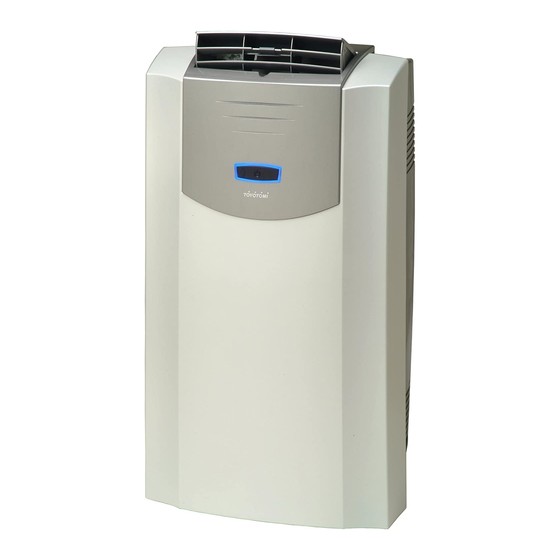
1. THE SUMMARY The idea behind the unit is to provide a localized supply of cool air. The unit will greatly enhance your personal comfort whether at a work station or even in your favorite chair. Four (4) casters enable you to move the unit easily from room to room. It cools and dries the air at the same time so that you can stay comfortable even when it's humid or rainy outside. - Page 3 3. DESCRIPTION OF PARTS AND COMPONENTS [FRONT] Air outlet grille Remote control (Removable) Horizontal louver Vertical louver Emergency ON/OFF switch Front panel [REAR] Air intake grille HAF filter (inside) Charcoal filter (inside) Cable hook Filter clamp (inside) Air intake opening Exhaust outlet Drain water outlet Caster...
- Page 4 4. NAME AND FUNCTIONS OF REMOTE CONTROL LCD display Power button Clock button Fan speed button Timer button Mode button C/F toggle button Down button UP button Launch signal indicator Clock indicator Fan speed indicator Timer setting indicator Mode indicator Timer ON/OFF indicator Symbols: Set temp indicator...
-
Page 5: Safety Tips
5. SAFETY TIPS IMPORTANT ¡ Read instructions carefully before operation. ¡ The unit should be operated when the room temperature is between 64˚F (18˚C) to 95˚F (35˚C). If the room temperature is below 64˚F (18˚C), ice may form on the coils. If the room temperature is above 95˚F (35˚C), the compressor will automatically shut off to protect itself. -
Page 6: Specifications
6. SPECIFICATIONS (I) SPECIFICATIONS ITEM UNIT TAD-T38J OUTER DIMENSIONS 20"(W) 16-1/2"(D) 36"(H) [508(W) 418(D) 915(H) mm] REFERENTIAL USING AREA 210~280 (19.5~26m RATED VOLTAGE V/Hz 115/60 RUNNING VOLTAGE 104-127 COOLING CAPACITY B.T.U. 13,000 DEHUMIDIFYING CAPACITY GAL/H 0.58 (2.2 L/H) RUNNING CURRENT 10.5... -
Page 7: Operation
7. OPERATION CONTROL PANEL LCD DISPLAY Launch signal indicator CLOCK indicator POWER CLOCK ON/OFF FAN SPEED TIMER setting indicator indicator MODE TIMER ON/OFF TIMER indicator SPEED ˚F/˚C indicator FAHRENHEIT/ SETTING TEMPERATURE Symbols: indicator CELSIUS MODE SELECTOR Cooling mode High speed Dehumidify mode Medium speed DOWN... - Page 8 LED SCREEN Blue/Yellow/Green Blue/Yellow/Green indicator indicator Blue/Yellow/Green Blue/Yellow/Green indicator indicator Emergency ON/OFF switch Blue LED Emergency ON/OFF Switch Note: • This switch is used when unit needs temporary 1. Display only when in operation mode. on/off. 2. When the unit is operation, clean indicator light (Blue •...
- Page 9 8. DISASSEMBLING WARNING • Make sure to disconnect the power source before disassembling the unit. • Carefully disassemble the unit. Do not touch evaporator and condenser directly or you may cut or injure your hands. CAUTION • Do not touch the compressor, the discharge pipes, or any parts that may be subjected to high temperature, before the temperature becomes low .
-
Page 10: Troubleshooting
9. TROUBLESHOOTING (I) Make sure that electric power is coming to the unit. AIR CONDITIONER CHECK THE NO POWER POWER TRIPPED WON'T START POWER SWITCH PLUG AND SOCKET RE-PLUGING THE ARE LOOSE POWER SUPPLY CORD TESTING BY CHANGE THE TIMER FAILURE ELECTROSCOPE SWITCH AIR CONDITIONER... -
Page 11: Troubleshooting Outline
TROUBLESHOOTING OUTLINE First, distinguish a location of malfunction. First thing to do is to check the circuit board. (1) Is it a malfunction of a controlled part? Is the circuit board trying to run? (2) Is it a malfunction of a controlling part? Ex: Fan does not turn. - Page 12 TROUBLESHOOTING When problem is unclear (also when there is a cooling-down error) Plug in Check plug lamp Plug lamp off Plug lamp on Check operation Check plug outlet vohage No response Some response to remote controllor and main body switch Voltage 115V No voltage Chock main body...
- Page 13 TROUBLESHOOTING Full water stop Operation stops due to full water. Check drain motor rotation It is dry operation. It is cool air operation. It is not rotating It is rotating Normal Normal Measure terminal voltage of main board Voltage 115 V No voltage Drain motor malfunction Main board malfunction...
- Page 14 TROUBLESHOOTING by Error indication on model TAD-T32G (Blue) (Blue) Malfunction of Thermistor on Alarm of full tank (Red) Malfunction of Room Heat Exchanger (Please Thermistor check if the environmental temp. is too low or not. Drain the drain water from drain water outlet on the back side of unit.
- Page 15 (Blue) (Blue) Re-check of Filter Cleaning PCB memory. It is not malfunction. Operate again after 5 min. Check the filter. After of disconnection from check, please press the power supply. Emergency button on Main Body for 4 sec. to release. Normal if the unit is Operation Circuit Board is operated for 30 min.
- Page 16 10. FUNCTION 1. Cooling operation Room temperature setting range is 61 ~ 90˚F (16 ~ 32˚C). Room temperature indication range is 32 ~ 122˚F (0 ~ 50˚C). State of operating is as shown below. Room More than More than temperature 150 seconds 150 seconds +2˚F (+1.0˚C)
- Page 17 COMPRESSOR ON – OFF ROOM TEMPERATURE FAN SPEED More than 79˚F (26˚C) Compressor ON Selected fan speed 9min. – 3min. (A) 77˚F ~ 73˚F (25˚C ~ 23˚C) 9min. – 3min. (B) 72˚F ~ 68˚F (22˚C ~ 20˚C) 6min. – 3min. (C) Less than 66˚F (19˚C) ¡During the dry operation, the control as mentioned above will change continuously.
-
Page 18: Parts List
PARTS LIST Optional PART # PART NAME PART # PART NAME PART # PART NAME 22740529 Base pan assembly 22740417 Indication lamp circuit 22740481 Window panel kit "C" 22740570 Caster 22740427 Front panel 22740476 Remote control 22740230 Float 22740435 Power supply cord 22740255 Air outlet nozzle (Option) 22740206... - Page 19 TOYOTOMI CO., LTD. 5-17, Momozono-cho, Mizuho-ku, Nagoya, 467-0855 Japan www.toyotomi.jp New 3/08 Printed in Japan...
Need help?
Do you have a question about the TAD-T38J and is the answer not in the manual?
Questions and answers